Modifying a USB-UART converter on a CP2102 chip for use as an Arduino programmer
This method requires the direct hands of nanobots - use the one described at your own peril and risk.
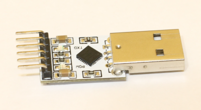
The USB-UART converter on the CP2102 chip, which came bundled with the Arduino Pro Mini and was declared as a programmer for it, came into my hands:
')
Connecting to the Arduino and trying to fill the sketch, I found that the fill does not occur. I get an error:
avrdude: stk500_getsync (): not in sync: resp = 0x00
The search answered the question why this is happening. It turned out that the RST at the output of the programmer is divorced in such a way that it is a digital input and is designed to reset the CP2102 chip from a signal from an external device, and not to reset the external device itself. Further searches led to an article where it was described how to fix it.
In the article I did not like that a separate wire was soldered to the chip. I wanted to try to use the existing RST output. Having a little understanding of the topology of the board, I found that the track from the RST pin through a through-hole is connected to one of the legs of the CP2102 chip and the resistance on the front side of the board.
Thus, it is necessary to cut the section of the track between the via hole and the CP2102 pin, and also to dissolve the SMD resistor above the POW inscription (“1001” on the resistor). Next, you need to connect with the help of wire output CP2102 "DTR" and the contact pad remaining after brazing the resistor, located closer to the inscription POW. This connects the “DTR” chip pin and the “RST” board pin.
Armed with a breadboarding knife and a soldering iron, I set to work. The result is such a miracle of technology:
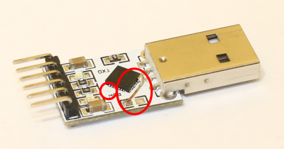
The circle on the left marks the cut track, and the oval on the right is a piece of soldered wire. In order for the microcircuit pins to stick together from tin, you should fill this side of the microcircuit with an alcohol-rosin mixture. Alcohol will quickly evaporate, however, when soldering, boiling rosin under the sting will not allow the tin to solder the legs together (of course, if you do not overdo it with tin).
Next, you should check the performance of the received board using the RealTerm program. Open the “Pins” tab - setting and resetting the DTR pin should not affect the operation of the DSR pin, however it should control the output voltage of the RST board.
When all the checks are completed, you can try to fill the sketch. We connect the Arduino Pro Mini to the converter:
(Converter) <-> (Arduino)
RST <-> DTR
TXD <-> RXD
RXD <-> TXD
GND <-> GND
5V <-> VCC
Now my sketch has been filled successfully.
I hope you will succeed!
The USB-UART converter on the CP2102 chip, which came bundled with the Arduino Pro Mini and was declared as a programmer for it, came into my hands:
')
Connecting to the Arduino and trying to fill the sketch, I found that the fill does not occur. I get an error:
avrdude: stk500_getsync (): not in sync: resp = 0x00
The search answered the question why this is happening. It turned out that the RST at the output of the programmer is divorced in such a way that it is a digital input and is designed to reset the CP2102 chip from a signal from an external device, and not to reset the external device itself. Further searches led to an article where it was described how to fix it.
In the article I did not like that a separate wire was soldered to the chip. I wanted to try to use the existing RST output. Having a little understanding of the topology of the board, I found that the track from the RST pin through a through-hole is connected to one of the legs of the CP2102 chip and the resistance on the front side of the board.
Thus, it is necessary to cut the section of the track between the via hole and the CP2102 pin, and also to dissolve the SMD resistor above the POW inscription (“1001” on the resistor). Next, you need to connect with the help of wire output CP2102 "DTR" and the contact pad remaining after brazing the resistor, located closer to the inscription POW. This connects the “DTR” chip pin and the “RST” board pin.
Armed with a breadboarding knife and a soldering iron, I set to work. The result is such a miracle of technology:
The circle on the left marks the cut track, and the oval on the right is a piece of soldered wire. In order for the microcircuit pins to stick together from tin, you should fill this side of the microcircuit with an alcohol-rosin mixture. Alcohol will quickly evaporate, however, when soldering, boiling rosin under the sting will not allow the tin to solder the legs together (of course, if you do not overdo it with tin).
Next, you should check the performance of the received board using the RealTerm program. Open the “Pins” tab - setting and resetting the DTR pin should not affect the operation of the DSR pin, however it should control the output voltage of the RST board.
When all the checks are completed, you can try to fill the sketch. We connect the Arduino Pro Mini to the converter:
(Converter) <-> (Arduino)
RST <-> DTR
TXD <-> RXD
RXD <-> TXD
GND <-> GND
5V <-> VCC
Now my sketch has been filled successfully.
I hope you will succeed!
Source: https://habr.com/ru/post/239401/
All Articles