Tracking station OpenDNS data centers
Question:
What will happen if we connect and put 12 LED blocks, 12 analog sensors in the case of birch plywood, connecting it all to the Arduino platform with two TI TLC5940 microprocessors?
Answer:
Monitoring system server load relative to the maximum value of the previous day, with every second update of the relevance of the data.
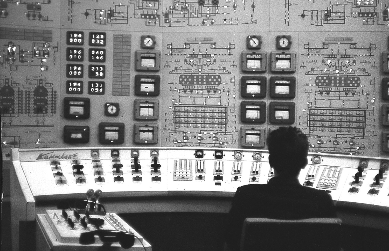
Being a fan of science fiction, all sorts of bunkers, nuclear power plants with hundreds of various sensors, he decided to create his own piece in the style of an old Soviet power station, which was once seen in the picture, with the possibility of finishing it more and more.
')
I am a very boring person in life, my only hobby is all kinds of crafts. It so happened that I was working as an OpenDNS manager, and my employer is an amazing company that operated data centers scattered around the world, serving 30 billion DNS requests each day. This huge number of requests was even greater, because according to statistics out of 100 ordinary Internet users 1 uses this service.
The anniversary of the founding of OpenDNS was approaching, and in order to celebrate this event, it occurred to me to build in our office something really unusual. I wanted to do a good thing that would not only look good but also become a part of what we actually do here. And also I really wanted to apply my old work with the Arduino platform.

• Design. It should contain both modern and retro elements.
• Managed by Arduino. It has been just a year since the last time I dealt with this platform, and obviously the time has come to return to the crafts with my favorite little microcontroller.
• The possibility of gradual refinement. To do everything at once in the plans was not.
• Attach your colleagues. At work, I am surrounded by brilliant engineers, if they are given instructions on how to display data on the information panel via USB, it will be much better for them than for me.
The canvas of birch plywood - cut so that it could go under the laser cutter.
Arduino - the one that I had in stock - Arduino Mega, it was a problem for the task. I needed a lot of PWM ports, while mine only had 13.
• TI TLC5940 - If you connect two such chips in series, this could solve my problem with the lack of PWM ports, increasing their number to 32.
• 5mm LEDs - the visual effect of the system was much better with them.
• 0-5 voltmeters - Arduino + TLC5940 are able to just maintain the output voltage up to 5 volts, which makes these sensors ideal.
• Miscellaneous - a little glue, a bundle of wires with a cross section of 0.5 mm, wire clips and the actual layout.
Having found the map in the network, I had to remove some parts from it, before laser engraving, the small islands were placed too close to each other, which could affect the correctness of their laser display on the stand. The raster image of the map had to be made vectorial in CorelDraw, this significantly accelerated the process of creating an image by a laser, by the way, the original quality of the map was 1200dpi.

Having found on the map the location of all our data centers, in their places, especially for LEDs, mounting holes were made on the stand. Since I had excellent 5 mm LEDs of diffuse illumination, I decided to put diodes of different colors on the stand. Instead of drilling one big hole, laser-burned the hole personally for each of the colors (Red, Green, Blue). Each hole had a diameter of 0.5 mm, and the distance between them was 0.75 mm. This placement allowed me to seamlessly lead the wires to the diodes.
At first I was confused by the scale on the voltmeter, but the stock sensors looked so beautiful that I still did not dare change anything in them and left it as it was. Their scale of 0-5 Volt seemed to add an entourage to the whole idea.
I had the experience of connecting wooden panels by means of laser-cut teeth, this is a convenient and reliable connection, and what is the only contrast between the laser-charred edges and the light wood linen! Having scored the necessary parameters into the laser cutter program, after which the whole structure was connected together, everything sat as it was, it was extremely difficult to disassemble it backwards.
Since my future plans are to finish building my “gadget”, the chosen method of fastening panels, this is just the right thing to do.
Laser cutter (TechShop) which I had had a working bed of 18x24 inches. That was enough to display a map of the world, but bad luck, New York and Washington were too close to place two rows of sensors in their place. I had to scale up.
Since one of the faces of the machine bed was 24 inches, I decided to make the whole layout 23x23x6 inches. My faceplate consisted of three parts, which for greater safety were glued to each other. This was done on the assumption that in the future, instead of the central panel, it will be possible to insert some kind of “control panel”, where additional sensors, toggle switches, buttons and so on will have to be placed. The side elements of the product served for its additional rigidity, in the future, to build up the structure, they can always be removed.
The photo speaks for itself. Maybe metal claws were superfluous here, connecting teeth firmly held the whole structure, but an excess of caution never hurts. The only thing that did not get into the frame is the Arduino, the module is located at the very bottom of the layout, along with two connected TLC5940 chips. Note the hole in the bottom left corner for the USB cable.

Hot glue miraculously secured all the wires in their places, and then as it turned out I had tangled the colors of the connections, the minus / cathode usually has a black connection color. The LEDs were inserted into the small but very tight connector, thus the electrical network was assembled. You may also notice that the plus / anode is usually indicated in red. The Ardunio board was attached to the bottom of the layout with tape.

I did not expect that I can experience so much happiness! Sitting at his desk at the headquarters of OpenDNS, after an unforgettable week of repeated tests and tests, to finally debug the system and come to a happy medium.
Making a serial connection on an Arduino is pretty simple. Two little tricks make a serial connection open and workable. My choice fell on the format of the three variables that characterized the object (LED, sensor), which should now be updated. For example, to upgrade Amsterdam to 100%, the current was increased to 100mA, for 50% it already corresponded to 50mA. The computer handled all the work related to the delivery of statistics and scaling it.

In matters of software, the lead engineer and a friend, Douz Tobacco, who created the entire control system, helped me. His script, written in Python, clears statistics on a specific position, translating them into percentages and sending them, performing such an operation every 0.085 seconds. Everything seemed to be going fine, but something unexpected happened: after a few minutes of work, the USB port on my friend's MacBook stopped responding and lasted until the computer was restarted. I started to worry about this, because before the presentation of my product at the party there were only 5 days left, but it could be more than just a glitch. Obviously the problem was in the control system. The day after a good dream, it dawned on me that the problem was in the wrong commentary on the sequential outputs in the Ardunio code. His buffer was overflowing and after a short time these oddities occurred. After fixing the code, the friend script worked fine!
What will happen if we connect and put 12 LED blocks, 12 analog sensors in the case of birch plywood, connecting it all to the Arduino platform with two TI TLC5940 microprocessors?
Answer:
Monitoring system server load relative to the maximum value of the previous day, with every second update of the relevance of the data.
Being a fan of science fiction, all sorts of bunkers, nuclear power plants with hundreds of various sensors, he decided to create his own piece in the style of an old Soviet power station, which was once seen in the picture, with the possibility of finishing it more and more.
')
Ready gadget
I am a very boring person in life, my only hobby is all kinds of crafts. It so happened that I was working as an OpenDNS manager, and my employer is an amazing company that operated data centers scattered around the world, serving 30 billion DNS requests each day. This huge number of requests was even greater, because according to statistics out of 100 ordinary Internet users 1 uses this service.
The anniversary of the founding of OpenDNS was approaching, and in order to celebrate this event, it occurred to me to build in our office something really unusual. I wanted to do a good thing that would not only look good but also become a part of what we actually do here. And also I really wanted to apply my old work with the Arduino platform.
The tasks that I needed to solve
• Design. It should contain both modern and retro elements.
• Managed by Arduino. It has been just a year since the last time I dealt with this platform, and obviously the time has come to return to the crafts with my favorite little microcontroller.
• The possibility of gradual refinement. To do everything at once in the plans was not.
• Attach your colleagues. At work, I am surrounded by brilliant engineers, if they are given instructions on how to display data on the information panel via USB, it will be much better for them than for me.
Spare parts
The canvas of birch plywood - cut so that it could go under the laser cutter.
Arduino - the one that I had in stock - Arduino Mega, it was a problem for the task. I needed a lot of PWM ports, while mine only had 13.
• TI TLC5940 - If you connect two such chips in series, this could solve my problem with the lack of PWM ports, increasing their number to 32.
• 5mm LEDs - the visual effect of the system was much better with them.
• 0-5 voltmeters - Arduino + TLC5940 are able to just maintain the output voltage up to 5 volts, which makes these sensors ideal.
• Miscellaneous - a little glue, a bundle of wires with a cross section of 0.5 mm, wire clips and the actual layout.
Stand - Card
Having found the map in the network, I had to remove some parts from it, before laser engraving, the small islands were placed too close to each other, which could affect the correctness of their laser display on the stand. The raster image of the map had to be made vectorial in CorelDraw, this significantly accelerated the process of creating an image by a laser, by the way, the original quality of the map was 1200dpi.
Having found on the map the location of all our data centers, in their places, especially for LEDs, mounting holes were made on the stand. Since I had excellent 5 mm LEDs of diffuse illumination, I decided to put diodes of different colors on the stand. Instead of drilling one big hole, laser-burned the hole personally for each of the colors (Red, Green, Blue). Each hole had a diameter of 0.5 mm, and the distance between them was 0.75 mm. This placement allowed me to seamlessly lead the wires to the diodes.
Voltmeters
At first I was confused by the scale on the voltmeter, but the stock sensors looked so beautiful that I still did not dare change anything in them and left it as it was. Their scale of 0-5 Volt seemed to add an entourage to the whole idea.
Panel assembly
I had the experience of connecting wooden panels by means of laser-cut teeth, this is a convenient and reliable connection, and what is the only contrast between the laser-charred edges and the light wood linen! Having scored the necessary parameters into the laser cutter program, after which the whole structure was connected together, everything sat as it was, it was extremely difficult to disassemble it backwards.
Since my future plans are to finish building my “gadget”, the chosen method of fastening panels, this is just the right thing to do.
Laser cutter (TechShop) which I had had a working bed of 18x24 inches. That was enough to display a map of the world, but bad luck, New York and Washington were too close to place two rows of sensors in their place. I had to scale up.
Since one of the faces of the machine bed was 24 inches, I decided to make the whole layout 23x23x6 inches. My faceplate consisted of three parts, which for greater safety were glued to each other. This was done on the assumption that in the future, instead of the central panel, it will be possible to insert some kind of “control panel”, where additional sensors, toggle switches, buttons and so on will have to be placed. The side elements of the product served for its additional rigidity, in the future, to build up the structure, they can always be removed.
Assembly and connection
The photo speaks for itself. Maybe metal claws were superfluous here, connecting teeth firmly held the whole structure, but an excess of caution never hurts. The only thing that did not get into the frame is the Arduino, the module is located at the very bottom of the layout, along with two connected TLC5940 chips. Note the hole in the bottom left corner for the USB cable.
Final build
Hot glue miraculously secured all the wires in their places, and then as it turned out I had tangled the colors of the connections, the minus / cathode usually has a black connection color. The LEDs were inserted into the small but very tight connector, thus the electrical network was assembled. You may also notice that the plus / anode is usually indicated in red. The Ardunio board was attached to the bottom of the layout with tape.
I did not expect that I can experience so much happiness! Sitting at his desk at the headquarters of OpenDNS, after an unforgettable week of repeated tests and tests, to finally debug the system and come to a happy medium.
Serial connection
Making a serial connection on an Arduino is pretty simple. Two little tricks make a serial connection open and workable. My choice fell on the format of the three variables that characterized the object (LED, sensor), which should now be updated. For example, to upgrade Amsterdam to 100%, the current was increased to 100mA, for 50% it already corresponded to 50mA. The computer handled all the work related to the delivery of statistics and scaling it.
In matters of software, the lead engineer and a friend, Douz Tobacco, who created the entire control system, helped me. His script, written in Python, clears statistics on a specific position, translating them into percentages and sending them, performing such an operation every 0.085 seconds. Everything seemed to be going fine, but something unexpected happened: after a few minutes of work, the USB port on my friend's MacBook stopped responding and lasted until the computer was restarted. I started to worry about this, because before the presentation of my product at the party there were only 5 days left, but it could be more than just a glitch. Obviously the problem was in the control system. The day after a good dream, it dawned on me that the problem was in the wrong commentary on the sequential outputs in the Ardunio code. His buffer was overflowing and after a short time these oddities occurred. After fixing the code, the friend script worked fine!
Source: https://habr.com/ru/post/239201/
All Articles