Work automation in nanoCAD using Visual Basic for Applications
The article describes one of the options for automating the work of designers in the CAD system nanoCAD, which allows to use to a large extent the parameterization of constructions and reduce the time for performing various tasks.

Many designers use MS Excel to perform mathematical calculations in tabular form. However, the functionality of the program is not limited to this. Using the Visual Basic for Applications (VBA) programming language integrated into Microsoft Office products, you can interact with the nanoCAD object model (and other products on its platform). In this article, we will demonstrate this possibility using a simple and universal example - we will create and adjust layers, draw a rectangle, dimension it and add text containing the figure area value.
')
The example uses MS Excel 2010 and nanoCAD 5.0, but the software version does not really matter.
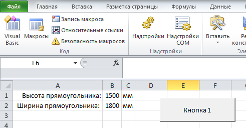
First you need to start Excel and prepare the data for building:
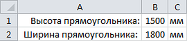
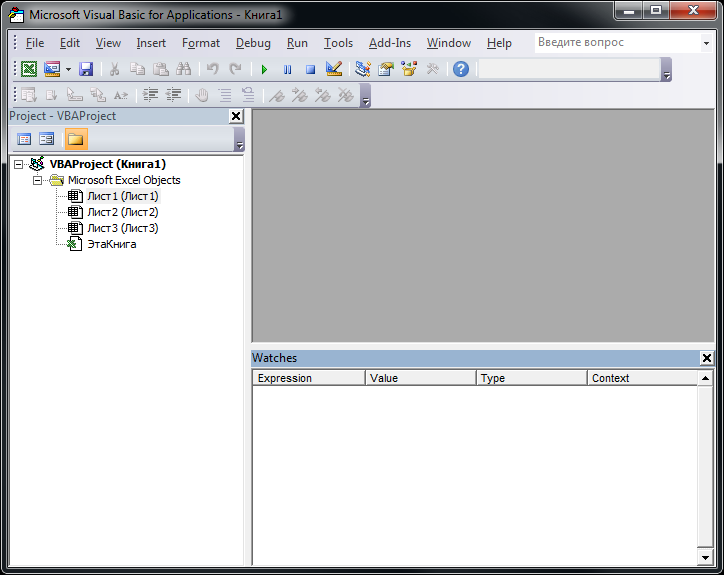
The data in cells B1 and B2 are written with a prime number, but they can be calculated using the formula. Now you need to switch to the Excel system for developing and debugging code embedded in Excel - press Alt + F11. The development environment window appears:
For the convenience of debugging the code, you need to connect certain libraries: in the Tools menu, select the References ... item and connect nanoCAD Type Library (NCAuto.dll) and OdaX Type Library (OdaX_csd.dll). By default, both libraries are located in the folder: C: \ Program Files \ Nanosoft \ nanoCAD 5.0 \ bin \.
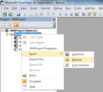
Now you need to create a module. Right click in the project tree on the folder Microsoft Excel Objects, in the drop-down list select Insert - Module:
In the window that appears, prepare the basis for the future program:
After explicitly declaring variables, it becomes much more convenient to work with them: just enter the name of the variable, put a full stop and the program will prompt all parameters and methods related to the object of this type.
Text after the apostrophe - comments to the code.
We declare the variables with the parameters of the future shape and assign them the values:
Create a new layer, assign a thickness and color to it:
We offer the user to choose the object insertion coordinates:
Constructing a rectangle consisting of four segments:
Dimensioning:
Calculate the area of the shape and paste the mtext into the center of the rectangle:
Completion of the basic function:
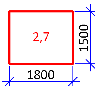
To run a written program, just press F5 (after that, do not forget to specify the insertion point in nanoCAD). The result of the program is shown in the picture:
The example demonstrates the ability to create basic primitives. More information on the nanoCAD object model can be found on the Internet, in particular, on the websites: vbamodel.narod.ru and www.alex160570.narod.ru/AcadVBA/vba01.htm
It is worth noting that to write so many lines of the same type of code in order to build one line, is laborious and boring, there is a high probability of making mistakes. For more convenience, you can create custom functions for constructing individual primitives. As an example, consider the function of constructing a segment. The function receives as parameters the X and Y coordinates of the beginning and end of the segment and builds it:
Additional user functions must be located after the base function, i.e. after the End Sub line related to the base function.
Now you can use abbreviated code to build a rectangle:
Similar user-defined functions can be written for any tasks that need to be performed more than once. At the same time, there are many operators available to the user, such as If ... Then ... Else, For ... Next, Do ... Loop, etc. For those users who are just familiar with programming, it will not be difficult to understand the possibilities of the language - for this there is help and numerous websites with examples of solved problems.
For the convenience of launching the created program, you can place the button directly on the Excel sheet. To do this, on the “Developer” tab, select “Insert” - “Form control” - “Button”:

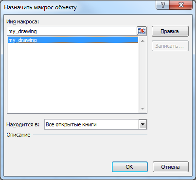
In the window that appears, select our basic function, then place the button on the sheet.
In one module, you can add any number of functions, create a button for each function and run them all from one place.
Sometimes there is a need to simulate the introduction of some commands in the command line. To do this, you can use the following structure:
This command will build a circle centered at point X: 100, Y: 100, Z: 0 with a radius of 1000 drawing units.
To debug created programs, you can display data in the form of pop-up windows or in the command line nanoCAD. After executing the following code:
A dialog box appears with the value of the variable x1:

To display the text in the command line nanoCAD, you can use the following code:
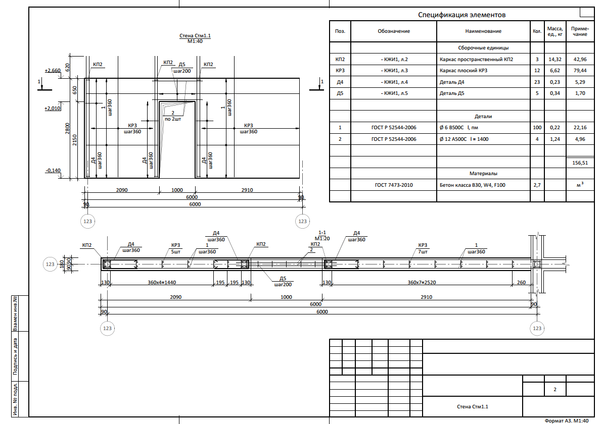
On the basis of this approach, we have developed a program for automating the construction of developments of monolithic reinforced concrete walls. After setting the initial data (about 30 parameters), at the output we get a practically finished drawing of the wall, taking into account the actual geometry, the presence of openings, and the adjoining of other walls:
Such an approach to work allows not only to reduce the time for preparing documentation in dozens, if not hundreds, of times, but also to completely eliminate the need for checking it.
In this article, we described how to build new primitives. But the nanoCAD object model allows editing the primitives existing in the drawing, including the nanoCAD DPS objects — the next article will be devoted to this.
Dmitry Rudenko , Chief Project Engineer, Fordevind Project Bureau
Update (2014-10-06):
Video demonstrating the work of such a script:
Many designers use MS Excel to perform mathematical calculations in tabular form. However, the functionality of the program is not limited to this. Using the Visual Basic for Applications (VBA) programming language integrated into Microsoft Office products, you can interact with the nanoCAD object model (and other products on its platform). In this article, we will demonstrate this possibility using a simple and universal example - we will create and adjust layers, draw a rectangle, dimension it and add text containing the figure area value.
')
The example uses MS Excel 2010 and nanoCAD 5.0, but the software version does not really matter.
First you need to start Excel and prepare the data for building:
The data in cells B1 and B2 are written with a prime number, but they can be calculated using the formula. Now you need to switch to the Excel system for developing and debugging code embedded in Excel - press Alt + F11. The development environment window appears:
For the convenience of debugging the code, you need to connect certain libraries: in the Tools menu, select the References ... item and connect nanoCAD Type Library (NCAuto.dll) and OdaX Type Library (OdaX_csd.dll). By default, both libraries are located in the folder: C: \ Program Files \ Nanosoft \ nanoCAD 5.0 \ bin \.
Now you need to create a module. Right click in the project tree on the folder Microsoft Excel Objects, in the drop-down list select Insert - Module:
In the window that appears, prepare the basis for the future program:
Option Explicit ' Public app As nanoCAD.Application ' nanoCAD Public ThisDrawing As nanoCAD.Document ' , nanoCAD Sub my_drawing() ' Set app = GetObject("", "nanoCAD.Application") ' nanoCAD app.Visible = True ' nanoCAD Set ThisDrawing = app.ActiveDocument ' , nanoCAD After explicitly declaring variables, it becomes much more convenient to work with them: just enter the name of the variable, put a full stop and the program will prompt all parameters and methods related to the object of this type.
Text after the apostrophe - comments to the code.
We declare the variables with the parameters of the future shape and assign them the values:
Dim r_height As Double, r_width As Double ', r_height = Range("B1").Value ' r_width = Range("B2").Value ' Create a new layer, assign a thickness and color to it:
Dim layer As AcadLayer ' "" Set layer = ThisDrawing.Layers.Add(" ") ' layer.Color = 21 '- layer.LineWeight = acLnWt050 ' 0.50 ThisDrawing.ActiveLayer = layer ' We offer the user to choose the object insertion coordinates:
Dim insert_point() As Double ' , insert_point = ThisDrawing.Utility.GetPoint("0,0,0", " ") ' insert_point(0) X, , ' insert_point(1) Y, insert_point(2) - Z Constructing a rectangle consisting of four segments:
Dim x1 As Double, x2 As Double, y1 As Double, y2 As Double x1 = insert_point(0) ' x2 = x1 + r_width ' y1 = insert_point(1) ' y2 = y1 + r_height ' Dim pt1(2) As Double, pt2(2) As Double, pt3(2) As Double, pt4(2) As Double ' 4 , pt1(0) = x1 ' pt1(1) = y1 ' pt2(0) = x2 ' pt2(1) = y1 ' pt3(0) = x2 ' pt3(1) = y2 ' pt4(0) = x1 ' pt4(1) = y2 ' Dim obj As AcadLine ' "" Set obj = ThisDrawing.ModelSpace.AddLine(pt1, pt2) ' Set obj = ThisDrawing.ModelSpace.AddLine(pt2, pt3) ' Set obj = ThisDrawing.ModelSpace.AddLine(pt3, pt4) ' Set obj = ThisDrawing.ModelSpace.AddLine(pt4, pt1) ' Dimensioning:
Dim pt5(2) As Double, pt6(2) As Double pt5(0) = (x1 + x2) / 2 ' pt5(1) = y1 - 500 ' pt6(0) = x2 + 500 ' pt6(1) = (y1 + y2) / 2 ' Dim dimrot As AcadDimRotated ' " " Set dimrot = ThisDrawing.ModelSpace.AddDimRotated(pt1, pt2, pt5, 0) ' Set dimrot = ThisDrawing.ModelSpace.AddDimRotated(pt2, pt3, pt6, 3.1416 / 2) ' ' Calculate the area of the shape and paste the mtext into the center of the rectangle:
Dim pt7(2) As Double pt7(0) = (x1 + x2) / 2 ' pt7(1) = (y1 + y2) / 2 ' Dim txt As AcadMText ' "" Set txt = ThisDrawing.ModelSpace.AddMText(pt7, 3000, CStr((x2 - x1) * (y2 - y1) / 1000000)) ' , – txt.AttachmentPoint = acAttachmentPointMiddleCenter ' "" " " Completion of the basic function:
End Sub To run a written program, just press F5 (after that, do not forget to specify the insertion point in nanoCAD). The result of the program is shown in the picture:
The example demonstrates the ability to create basic primitives. More information on the nanoCAD object model can be found on the Internet, in particular, on the websites: vbamodel.narod.ru and www.alex160570.narod.ru/AcadVBA/vba01.htm
It is worth noting that to write so many lines of the same type of code in order to build one line, is laborious and boring, there is a high probability of making mistakes. For more convenience, you can create custom functions for constructing individual primitives. As an example, consider the function of constructing a segment. The function receives as parameters the X and Y coordinates of the beginning and end of the segment and builds it:
Sub my_line(x1 As Double, y1 As Double, x2 As Double, y2 As Double) Dim pt1(2) As Double, pt2(2) As Double pt1(0) = x1 ' pt1(1) = y1 ' pt2(0) = x2 ' pt2(1) = y2 ' Dim obj As AcadLine Set obj = ThisDrawing.ModelSpace.AddLine(pt1, pt2) ' End Sub Additional user functions must be located after the base function, i.e. after the End Sub line related to the base function.
Now you can use abbreviated code to build a rectangle:
Dim x1 As Double, x2 As Double, y1 As Double, y2 As Double x1 = insert_point(0) ' x2 = x1 + r_width ' y1 = insert_point(1) ' y2 = y1 + r_height ' my_line x1, y1, x2, y1 ' my_line x2, y1, x2, y2 ' my_line x2, y2, x1, y2 ' my_line x1, y2, x1, y1 ' Similar user-defined functions can be written for any tasks that need to be performed more than once. At the same time, there are many operators available to the user, such as If ... Then ... Else, For ... Next, Do ... Loop, etc. For those users who are just familiar with programming, it will not be difficult to understand the possibilities of the language - for this there is help and numerous websites with examples of solved problems.
For the convenience of launching the created program, you can place the button directly on the Excel sheet. To do this, on the “Developer” tab, select “Insert” - “Form control” - “Button”:
In the window that appears, select our basic function, then place the button on the sheet.
In one module, you can add any number of functions, create a button for each function and run them all from one place.
Sometimes there is a need to simulate the introduction of some commands in the command line. To do this, you can use the following structure:
ThisDrawing.SendCommand "CIRCLE" & vbCr & "100,100,0" & vbCr & "1000" & vbCr This command will build a circle centered at point X: 100, Y: 100, Z: 0 with a radius of 1000 drawing units.
To debug created programs, you can display data in the form of pop-up windows or in the command line nanoCAD. After executing the following code:
MsgBox "x1: " & x1 A dialog box appears with the value of the variable x1:
To display the text in the command line nanoCAD, you can use the following code:
ThisDrawing.Utility.Prompt "x1: " & x1 & " y1: " & y1 On the basis of this approach, we have developed a program for automating the construction of developments of monolithic reinforced concrete walls. After setting the initial data (about 30 parameters), at the output we get a practically finished drawing of the wall, taking into account the actual geometry, the presence of openings, and the adjoining of other walls:
Such an approach to work allows not only to reduce the time for preparing documentation in dozens, if not hundreds, of times, but also to completely eliminate the need for checking it.
In this article, we described how to build new primitives. But the nanoCAD object model allows editing the primitives existing in the drawing, including the nanoCAD DPS objects — the next article will be devoted to this.
Dmitry Rudenko , Chief Project Engineer, Fordevind Project Bureau
Update (2014-10-06):
Video demonstrating the work of such a script:
Source: https://habr.com/ru/post/238867/
All Articles