XNA 3D: an introduction to custom shader and a little bit of a prototype
Hi, Habrahabr! Unfortunately, for a long time did not write on Habr. Personal affairs were completely opposed to sit down and write a couple of articles on game development. Maybe it is for the better. During these two years I have gained a lot of experience and are always happy to share it. It is worth noting that I completely refused to create 2D games: I do not mind them, but developing games in 3D is much more interesting and fun! Traditionally, XNA 4.0 will be used as a tool, why is XNA 4.0 a dear listener? And all because, he still remains relevant for indie developers. We have a language with a very low entry - C #. There is the same XNA framework with the necessary initial classes / structures and algorithms. And there is DirectX with shader support, right up to Shader Model 3.0 . If you, %% username , read me for the first time, you can read my articles dated 2012 as well. Not to say that they are 100% relevant, that there are no errors in them, but they can give a certain base. As it is probably understandable, I will only write about 3D : I did not fully define the list of topics, but I think that I will form them pretty quickly.
So far, exactly conceived two articles:
- “XNA 3D: an introduction to custom shader and a little bit of a prototype”
- “XNA 3D: HDR vs LDR , the implementation of HDR "
')
Now I’ll give an introduction to the custom shader and implement a simple prototype of the FEZ game.
Introduction
When we worked with 2D - we didn't bother with any matrices, we just gave our textures and their position to the local SpriteBatch , and he drew them to us. But I want to say: that everything that he draws is 3D : only one of the coordinates is zero (in the XNA , the Z coordinate), well, a special projection is used (about them later). Projection - transfer of coordinates from 3D space to 2D screen space. Also, one of the overloads of the SpriteBatch method supports a parameter in the form of a matrix: through it we made the camera. And now we give analogies with 3D . Those coordinates that we passed to SpriteBatch as the position of the texture (as well as its rotation and size) - this is called the world transformation (as well as the world matrix). That matrix parameter in SpriteBatch.Begin is the view matrix . And a special projection matrix, which we cannot change in SpriteBatch . And now once again from a different angle: any model consists of points - called vertices , the whole position (transformation) of these vertices is a local coordinate system. Next, we need to make them global, thanks to this - we can use the same model and draw it in different places with different rotation / size. After that, we have to shift this transformation to the camera. And after we calculated the final transformations, we project them from 3D space to screen 2D.
Graphic device: shader and models
I covered the topic of shaders in past articles and how post-image processing is done using them. We used only pixel shaders. In fact, everything is more complicated. In addition to pixel shaders, there are vertex ones (I consider the situation before SM3.0 inclusive). These shaders operate on vertices, not pixels. Those. performed for each vertex. Here we have the magic of transformation. Let's try to create a new .fx file in XNA and analyze it:
float4x4 World; float4x4 View; float4x4 Projection; The first three lines are just our matrices. All these values are taken from the so-called constant buffer (about the buffers a little later). Next comes the implementation of the input-output structures:
struct VertexShaderInput { float4 Position : POSITION0; }; struct VertexShaderOutput { float4 Position : POSITION0; }; This is the simplest implementation of the vertex shader's input-output: we get the vertex position on the POSITION0 channel and, as output data, provide information for the next part of the graphics pipeline (already transformed data) - the rasterizer .
Well, the last part of the .fx file is the shaders themselves:
VertexShaderOutput VertexShaderFunction(VertexShaderInput input) { VertexShaderOutput output; float4 worldPosition = mul(input.Position, World); float4 viewPosition = mul(worldPosition, View); output.Position = mul(viewPosition, Projection); return output; } float4 PixelShaderFunction(VertexShaderOutput input) : COLOR0 { return float4(1, 0, 0, 1); } The vertex shader gets the position of the vertex in the “model” space, then leads to the global, specific and ultimately to the screen. Well, the pixel shader fills everything with red.
A little bit about matrices
I will not go into the details of these matrices (there is a lot of such information: because it is quite common): I will just say how this is in XNA .
The world matrix is defined by the Scale Rotation Translation view:
Matrix world = Matrix.CreateScale(x, y, z) * Matrix.CreateFromYawPitchRoll(y, p, r) * Matrix.CreateTranslation(x, y, z); Multiplication of matrices is noncommutative, so order is important here.
View matrix (camera matrix):
Matrix view = Matrix.CreateLookAt(vpos, targetpos, up); Generally speaking, you can use the SRT matrix, but in XNA there is a convenient tool to make it easier.
Vpos is the camera position, targetpos is the point where the camera is looking, and up is the upward vector (usually Vector3.Up ).
Well, the last and most important thing is the projection matrix. In the most standard case, there are two of them: orthographic projection and perspective . Looking ahead, orthographic is used for 2D (and to some extent for isometric), and promising in other cases (for example, 3D shooters).
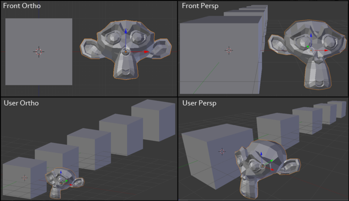
Our eye is designed in such a way that we perceive all objects in a perspective projection, i.e. the more distant the object, the less it seems to us. The orthogonal projection at first glance looks strange, because the size of the object does not depend on the distance to it. It is like if we viewed the scene from an infinitely long distance. That is why it is used for 2D games, because we do not need to consider the distance to a specific polygon.
Model view
When loading a model from a hard disk, we load (in the simplest case) the following information:
POSITION - vertex position.
NORMAL is the vertex normal.
TEXCOORD - texture coordinate (UV-scan).
This information is called vertex channels (as with the Red channel analogy of an RGB space).
And also, we load the special information which is called as indexes . Now let's try to make it out.
We need to draw a square, the square consists of four points. The graphics device operates with triangles only . Any shape can be divided into triangles. And now, if you describe this square for a graphic device, you will need 6 vertices ( 3 for each triangle). But I want to replace that some vertices (or rather their positions) will be equal in this case. For this, a special index buffer was invented. Imagine that we have 4 support vertexes that describe a square: v1, v2, v3, v4 . And now you can build an index buffer : [0, 1, 2, 1, 2, 3] - the graphic device for these indices will find and use vertices from the vertex buffer: [v1, v2, v3, v2, v3, v4] . This approach is very convenient, because greatly reduces the volume of the vertex buffer , as well as expands the functionality for drawing. For example, you can set a large vertex buffer (an extremely slow operation), and then draw certain parts of the model — changing only the index buffer (a fast operation compared to installing a vertex buffer).
XNA has the following classes: VertexBuffer and IndexBuffer . We will not consider creating them directly in the code, and for this we will use the loading of a simple model.
Create a simple model and save it in FBX format:
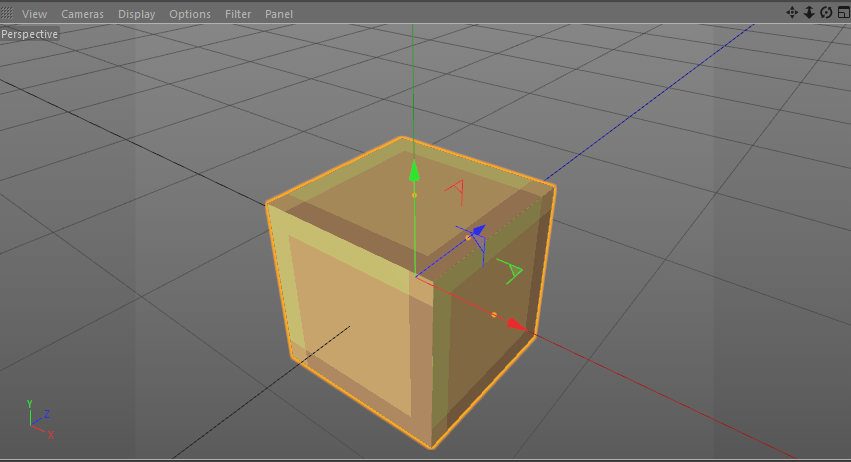
After that - we can extract the already created VertexBuffer and IndexBuffer :
_vertexBuffer = boxModel.Meshes[0].MeshParts[0].VertexBuffer; _indexBuffer = boxModel.Meshes[0].MeshParts[0].IndexBuffer; Attention! This case is only suitable for the simplest model with one untransformed mesh. A complex model may have several vertex / index buffers. Also, parts of a model can have their own transformation in model space.
Implementation
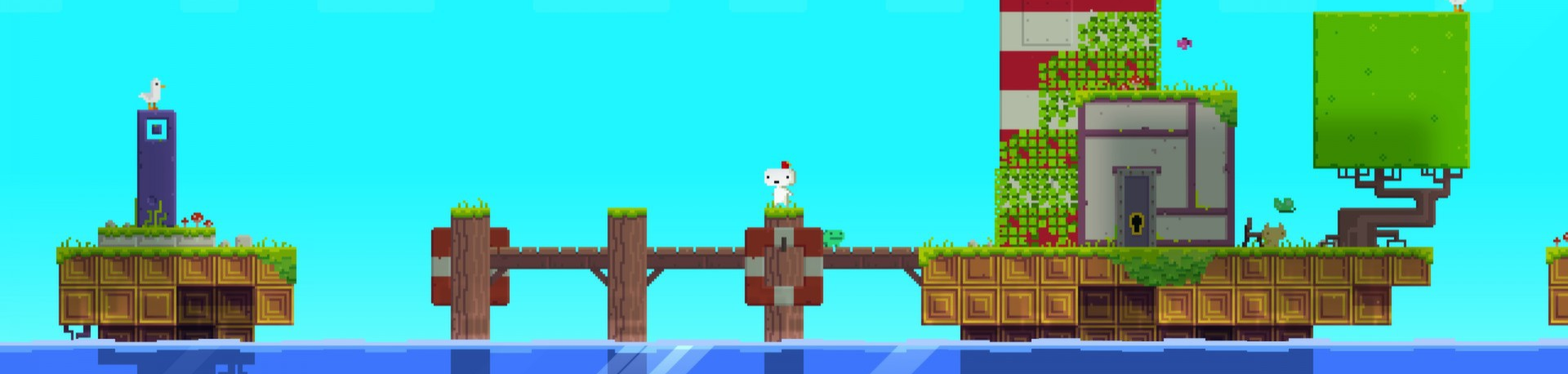
Now everything is ready and let's make some prototype. There is such a great indie game - FEZ . Many of my friends asked how such a gameplay is possible in terms of implementation? In fact, there is nothing abstruse, just use the orthogonal (orthographic) projection (and the information about the world is contained in the 3D view, in contrast to the classic 2D game) with the ability to rotate the world.
A little description of the gameplay with Wikipedia:
Fez is presented in the form of a 2D platformer in which Gomez can walk, jump, climb and manipulate objects. Nevertheless, the player can at any time shift perspectives, rotating the world 90 degrees relative to the screen. This allows you to detect doors and aisles, and also causes the platform to rebuild. Since the volume is not typical 2D-games, the player can (and must) use this mechanics to perform actions that are usually impossible in this 3D-world. For example, standing on a moving platform and shifting perspective by 90 degrees, Gomez can move to another platform that was previously on the opposite side of the screen. Returning to the original perspective after moving, it turns out that Gomez has moved a long distance.
And the video of the gameplay itself:
Let's start!
Load the base geometry:
Model boxModel = Content.Load<Model>("simple_cube"); _vertexBuffer = boxModel.Meshes[0].MeshParts[0].VertexBuffer; _indexBuffer = boxModel.Meshes[0].MeshParts[0].IndexBuffer; Load two simple 16x16 textures:
_simpleTexture1 = Content.Load<Texture2D>("simple_texture1"); _simpleTexture2 = Content.Load<Texture2D>("simple_texture2"); And load the previously created shader (effect) (.fx):
_effect = Content.Load<Effect>("simple_effect"); The whole thing we do in the method: LoadContent .
And now let's try to draw our model ( Draw method):
Simple rendering
// GraphicsDevice.SetVertexBuffer(_vertexBuffer); GraphicsDevice.Indices = _indexBuffer; // Matrix view = Matrix.CreateLookAt(Vector3.One * 2f, Vector3.Zero, Vector3.Up); Matrix projection = Matrix.CreatePerspectiveFieldOfView(MathHelper.ToRadians(45f), GraphicsDevice.Viewport.AspectRatio, 0.01f, 100f); float dt = (float)gameTime.TotalGameTime.TotalSeconds; Matrix world = Matrix.CreateFromYawPitchRoll(dt, dt, dt); // _effect.Parameters["View"].SetValue(view); _effect.Parameters["Projection"].SetValue(projection); _effect.Parameters["World"].SetValue(world); // _effect.CurrentTechnique.Passes[0].Apply(); // GraphicsDevice.DrawIndexedPrimitives(PrimitiveType.TriangleList, 0, 0, _vertexBuffer.VertexCount, 0, _indexBuffer.IndexCount / 3); Attention! Such a case is only suitable for the simplest shader with one pass. A complex shader can have several passes.
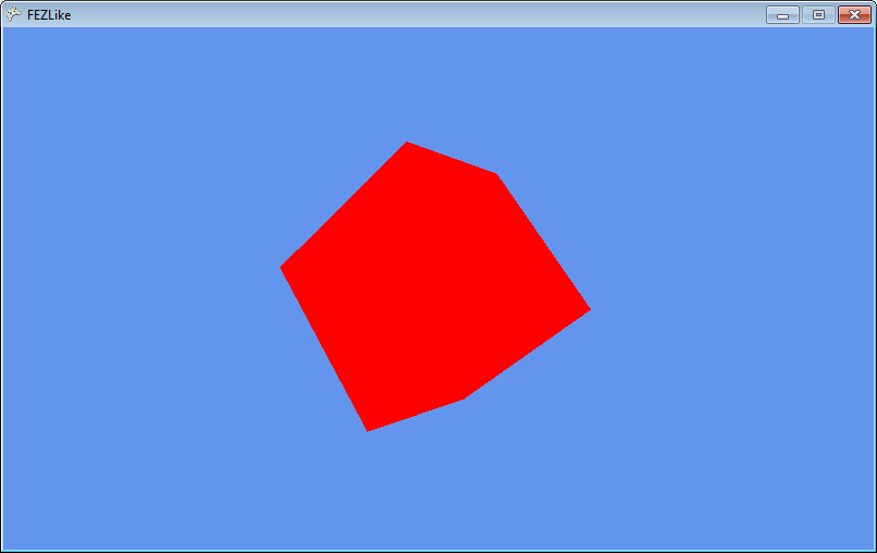
Here we used a perspective projection with a viewing angle of 45 degrees. Everything is working. Now, we need to set the texture of our model. When saving a model from Cinema 4D to FBX format, the following channels were available: POSITION , NORMAL , TEXCOORD (UV). Let's return to our shader and add one of the channels to the input / output data:
struct VertexShaderInput { float4 Position : POSITION0; float2 UV : TEXCOORD0; }; struct VertexShaderOutput { float4 Position : POSITION0; float2 UV : TEXCOORD0; }; These will be our texture coordinates. The texture coordinate links the vertex to a position on a two-dimensional texture.
And in the vertex shader, pass without changes:
output.UV = input.UV; After the rasterization stage, we get the TEXCOORD0 values interpolated (in a triangle) and we can get the texture color values in the pixel shader:
float4 PixelShaderFunction(VertexShaderOutput input) : COLOR0 { return tex2D(TextureSampler, input.UV); } But in order to get the color values of the texture on UV - you need to set this very texture. To do this, there are samplers that, in addition to the texture itself, contain information about what to do if, on a rasterized triangle, the texture on the screen turned out to be too large or small.
Since we set the parameters explicitly in the shader, keep the tradition and create a sampler in the shader:
texture Texture; sampler2D TextureSampler = sampler_state { Texture = <Texture>; }; Well, let's set the texture as a parameter:
_effect.Parameters["Texture"].SetValue(_simpleTexture1); We see:
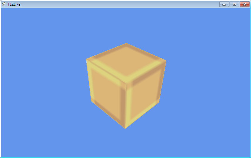
But since the texture on the screen turned out to be more than 16x16 - it was interpolated according to the settings of the sampler. This is not what we need, so let's change the filtering in the sampler:
texture Texture; sampler2D TextureSampler = sampler_state { Texture = <Texture>; MipFilter = POINT; MinFilter = POINT; MagFilter = POINT; }; 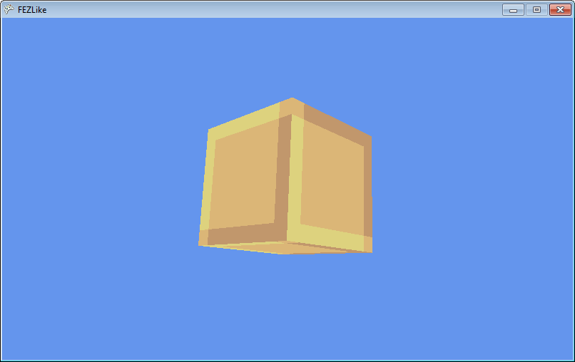
By the way, I talked about filtering in articles earlier .
Now everything is set up and it's time to combine our 2D and 3D. We introduce the Block class:
public class Block { public enum BlockType { First, Second } public Matrix Transform; public BlockType Type; } Where Transform is our world matrix for an object.
And a simple generation of these blocks:
Block generation
private void _createPyramid(Vector3 basePosition, int basesize, int baseheight, Block.BlockType type) { for (int h = 0; h < baseheight; h++) { int size = basesize - h * 2; for (int i = 0; i < size; i++) for (int j = 0; j < size; j++) { Block block = new Block(); Vector3 position = new Vector3( -(float)size / 2f + (float)i, (float)h, -(float)size / 2f + (float)j) + basePosition; block.Transform = Matrix.CreateTranslation(position); block.Type = type; _blocks.Add(block); } } } Well, the ability to draw a lot of models with different transformations:
Rendering
GraphicsDevice.SetVertexBuffer(_vertexBuffer); GraphicsDevice.Indices = _indexBuffer; Matrix view = Matrix.CreateLookAt(Vector3.One * 10f, Vector3.Zero, Vector3.Up); Matrix projection = Matrix.CreatePerspectiveFieldOfView(MathHelper.ToRadians(45f), GraphicsDevice.Viewport.AspectRatio, 0.01f, 100f); _effect.Parameters["View"].SetValue(view); _effect.Parameters["Projection"].SetValue(projection); foreach (Block block in _blocks) { Matrix world = block.Transform; _effect.Parameters["Texture"].SetValue(_simpleTexture1); _effect.Parameters["World"].SetValue(world); _effect.CurrentTechnique.Passes[0].Apply(); GraphicsDevice.DrawIndexedPrimitives(PrimitiveType.TriangleList, 0, 0, _vertexBuffer.VertexCount, 0, _indexBuffer.IndexCount / 3); } And the last stage - create our world:
_createPyramid(new Vector3(-7f, 0f, 5.5f), 10, 5, Block.BlockType.First); _createPyramid(new Vector3(7f, 0f, 0f), 5, 3, Block.BlockType.Second); _createPyramid(new Vector3(7f, -7f, 7f), 7, 10, Block.BlockType.First); 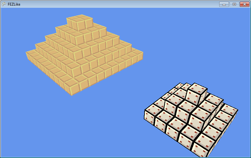
It remains the most important thing, the creation of the desired projection and the ability to rotate our world.
We will set the projection as follows:
Matrix projection = Matrix.CreateOrthographic(20f * GraphicsDevice.Viewport.AspectRatio, 20f, -100f, 100f); Where 20f - a kind of “zoom”. A -100f and 100f near and far edge of clipping.
And species:
Matrix view = Matrix.CreateRotationY(MathHelper.PiOver2 * _rotation); Where _rotation is rotation. For “soft” rotation, you can use the MathHelper.SmoothStep function, which is nothing more than a cubic lerp .
For rotation, we introduce four variables:
/* ROTATION */ float _rotation; float _rotationTo; float _rotationFrom; float _rotationDelta; And update our Update :
Rotation control
if (keyboardState.IsKeyDown(Keys.Left) && _prevKeyboardState.IsKeyUp(Keys.Left) && _rotationDelta >= 1f) { _rotationFrom = _rotation; _rotationTo = _rotation - 1f; _rotationDelta = 0f; } if (keyboardState.IsKeyDown(Keys.Right) && _prevKeyboardState.IsKeyUp(Keys.Right) && _rotationDelta >= 1f) { _rotationFrom = _rotation; _rotationTo = _rotation + 1f; _rotationDelta = 0f; } if (_rotationDelta <= 1f) { _rotationDelta += (float)gameTime.ElapsedGameTime.TotalSeconds * 2f; _rotation = MathHelper.SmoothStep(_rotationFrom, _rotationTo, _rotationDelta); } I’ll draw your attention to the fact that gameTime.ElapsedGameTime is used here : in moments when changes in a variable in a game occur gradually, you need to take this value into account, because FPS can be different for everyone .
And finally, a few words about the implementation of the world. You can generate a world (physical) for each rotation when loading a level and rotating it to check whether the player is able to go to the desired level from the current position and what position he will go to.
Comment on the prototype
Of course, there are a lot of problems in this prototype: for example, faces that we will never see (if I wrote about the dynamic construction of geometry, then the article would have grown many times). In addition, the whole thing - you can implement without a custom shader , using BasicEffect . But for future articles it is important to understand how to make a custom shader without binding to the model.
Source code + binary: here
Conclusion
In this article, I made some introduction and showed a prototype of the famous game, where no perspective is used as a projection. After this introduction, I plan to explain some of the game development chips in three dimensions, I will try to introduce in some detail the shaders (both pixel and vertex). Also introduce some techniques, such as HDR , Deferred Rendering (I used to do this for 2D, but that method is more likely modified with Forward rendering than with Deferred-technique), VTF . Well, since I publish exclusively on habrahabr, I always welcome comments and suggestions: if you don’t know how something works in a game (especially AAA class games are welcome), or you are interested in the implementation of a particular effect, then Feel free to write a comment . I will try to tell about it as much as possible.
PS The best motivation for me is your interest.
PSS we are all human and we make mistakes and therefore, if you find a mistake in the text - write me a personal message, and do not rush to write an angry comment!
Source: https://habr.com/ru/post/238385/
All Articles