Dent in space with DisplacementMapFilter
In my spare time, I sculpt in the field of igodeling.
The last hand-made article is devoted to the classic tower defense on a space theme:
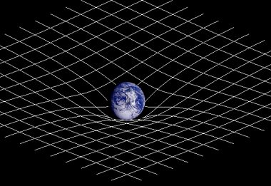
Since the game is done in isometric, I wanted to portray the scene like this
taken from here
Thank you, a kind person in a profile conference prompted the search path - DisplacementMapFilter.
I opened the documentation, copied a couple of examples, tried to write my own filter - it did not work right away.
I will not describe my search for a solution - I will immediately present the result (on google code ) and make a few important, in my opinion, explanations.
')
The code for the working classes DisplacementMapFilterGravity and DisplacementMapFilterGravityParams is laid out as it is - i.e. at the time of this writing, they are the same as in the project. The Main class is for demonstration.
class Main
class DisplacementMapFilterGravity
1. In the Main class I prepare the data for the "manufacture" of the filter card
I put the coordinates immediately for isometry (after all, the classes are real and torn from the render for isometry)
2. after passing the parameters to DisplacementMapFilterGravity, I draw “gradient pancakes” - blanks for “dents”
it will turn out something like (but much larger - I depicted it smaller, so as not to occupy space on the page)
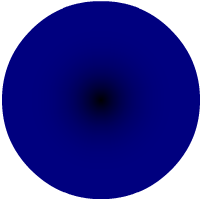
dark color - future depression, light (0x80) - plane level
Here I want to pay special attention to the magic number 0x80 - this is the value of the color channel (relative to which the filter will perform pixel-by-pixel offset) means zero level of distortion - the filter WILL NOT move a pixel with this color value. Those. - since the level of the grid plane in this case is taken to be zero (the color of the channel is 0x80), so that the edges of the depression smoothly pass into the grid plane, they should also have this value (0x80).
Now about the function that in the loop gives us a similar picture. This is nothing but Easing.easeOutCircular, whose graph looks like this
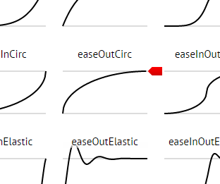
examples of other functions can be viewed in the cheat sheet , take implementation here , invent new
line of code (how to deal with easing) - color = gr.func (r, deep, 0x80-deep, radius-1); - you can understand by reading even a short article right there on Habré “jQuery Easing. Custom easing'i »
3. after “baking” , the pancakes are copied into separate bitmaps using the matrix transformation (you need to get their isometric projection) and put the common container in its isometric coordinates
As a result, the container with the contents looks like this: “pancakes” overlap each other - there is no SMOOTH transition between them
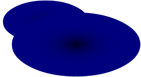
4. you need to make a smooth transition between future cavities . In short: all the “pancakes” are taken successively, colors are compared at the intersections, and the resulting color is chosen corresponding to a greater depth (darker). In the end, you get something like this:
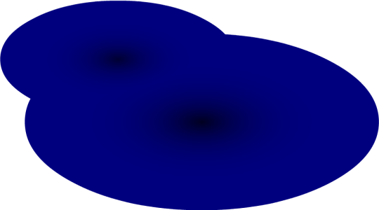
5. in the final result, white areas, of course, are “painted over” on the same 0x80 (everything is copied into the bitmap with the background color 0x80).
6. after applying the filter, we get a new grid:
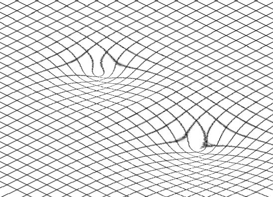
Troughs look unpresentable, well, so we cover them with planets:

The grid in the field of deformation also looks "fragile" - well, you will need to ask the advice of the artist if it is possible to hide it somehow. Well, if you can not, then at least you can use it in prototypes - like here, for example .
The last hand-made article is devoted to the classic tower defense on a space theme:
- given interplanetary space
- trajectories of asteroids are determined by the gravitational fields of the planets
- "Cannon" rockets destroy asteroids
Since the game is done in isometric, I wanted to portray the scene like this
taken from here
There was a question - how?
- use of any photoshop - absolutely unacceptable, for obvious reasons
- to fasten a 3d engine for drawing a grid was not very desirable
Thank you, a kind person in a profile conference prompted the search path - DisplacementMapFilter.
I opened the documentation, copied a couple of examples, tried to write my own filter - it did not work right away.
I will not describe my search for a solution - I will immediately present the result (on google code ) and make a few important, in my opinion, explanations.
')
The code for the working classes DisplacementMapFilterGravity and DisplacementMapFilterGravityParams is laid out as it is - i.e. at the time of this writing, they are the same as in the project. The Main class is for demonstration.
class Main
- drawGrid () - draws a grid and saves it to the bitmap, which clings onto the stage
- updateGravities () - sets the filter class.
- adds two gravitational areas, according to the ISOMETRIC coordinates (remember, when you experiment - because the classes are torn out from the isometric render)
- applies a filter to a grid drawn in a bitmap
- drawPlanets () - draws "planets". In fact - it's just the scenery, projected on the "dents"
class DisplacementMapFilterGravity
- createDisplacementFilter - the name speaks for itself
- createDisplacementMap - creates a filter map
- getShape - generates a Shape of a SPECIFIC gravity area
- getRectangleIntersection - an auxiliary method, finds areas of intersection of gravitational fields
Now I will describe the algorithm in detail:
1. In the Main class I prepare the data for the "manufacture" of the filter card
private function updateGravities():void { var funcs:Array = [Easing.easeOutQuart];//, Easing.easeOutCubic, Easing.easeOutCircular]; var arr:Array = []; var params:DisplacementMapFilterGravityParams; params = new DisplacementMapFilterGravityParams(); params.x = 250; params.y = 50; params.radius = 200; params.func = funcs[arr.length%funcs.length]; arr.push( params ); params = new DisplacementMapFilterGravityParams(); params.x = 500; params.y = 100; params.radius = 300; params.func = funcs[arr.length%funcs.length]; arr.push( params ); ... } I put the coordinates immediately for isometry (after all, the classes are real and torn from the render for isometry)
2. after passing the parameters to DisplacementMapFilterGravity, I draw “gradient pancakes” - blanks for “dents”
private function getShape(gr:DisplacementMapFilterGravityParams):Shape { var shape:Shape = new Shape(); var g:Graphics = shape.graphics; var color:uint; var radius:int = gr.radius; // TODO "" (.. , ) var deep:int = 10000/radius; for(var r:Number=radius-1; r>-1; r--) { color = gr.func(r, deep, 0x80-deep, radius-1); g.beginFill(color); g.drawCircle(0, 0, r); g.endFill(); } return shape; } it will turn out something like (but much larger - I depicted it smaller, so as not to occupy space on the page)
dark color - future depression, light (0x80) - plane level
Here I want to pay special attention to the magic number 0x80 - this is the value of the color channel (relative to which the filter will perform pixel-by-pixel offset) means zero level of distortion - the filter WILL NOT move a pixel with this color value. Those. - since the level of the grid plane in this case is taken to be zero (the color of the channel is 0x80), so that the edges of the depression smoothly pass into the grid plane, they should also have this value (0x80).
Now about the function that in the loop gives us a similar picture. This is nothing but Easing.easeOutCircular, whose graph looks like this
examples of other functions can be viewed in the cheat sheet , take implementation here , invent new
line of code (how to deal with easing) - color = gr.func (r, deep, 0x80-deep, radius-1); - you can understand by reading even a short article right there on Habré “jQuery Easing. Custom easing'i »
3. after “baking” , the pancakes are copied into separate bitmaps using the matrix transformation (you need to get their isometric projection) and put the common container in its isometric coordinates
public function createDisplacementMap():void { ... var gr:DisplacementMapFilterGravityParams; for(var i:int=0; i<arrGravities.length; i++) { gr = arrGravities[i]; shape = getShape(gr); var bmd:Bitmap = sprite.addChild(new Bitmap(new BitmapData(shape.width*2+2, shape.height+2, true, 0x00ff00))) as Bitmap; bmd.bitmapData.draw(shape, new Matrix(1, .5, -1, .5, shape.width + 1, shape.height/2 + 1)); bmd.x = UtilsIsometric.xToIsoX(int(gr.x), int(gr.y)) - bmd.width/2; bmd.y = UtilsIsometric.yToIsoY(int(gr.x), int(gr.y)) - bmd.height/2; } ... } As a result, the container with the contents looks like this: “pancakes” overlap each other - there is no SMOOTH transition between them

4. you need to make a smooth transition between future cavities . In short: all the “pancakes” are taken successively, colors are compared at the intersections, and the resulting color is chosen corresponding to a greater depth (darker). In the end, you get something like this:

public function createDisplacementMap():void { ... {// , var child:Bitmap = sprite.getChildAt(0) as Bitmap; var rectChild:Rectangle = child.getBounds(sprite); bitmapdata.draw(child, new Matrix(1,0,0,1,rectChild.left-rect.left + 1, rectChild.top-rect.top + 1)); var rectSumm:Rectangle = rectChild.clone(); for(var l:int=1; l<sprite.numChildren; l++) { child = sprite.getChildAt(l) as Bitmap; rectChild = child.getBounds(sprite); var rectIntersection:Rectangle = getRectangleIntersection(rectSumm, rectChild); var bmdIntersection:BitmapData; if(rectIntersection != null) { bmdIntersection = new BitmapData(rectIntersection.width, rectIntersection.height, false, 0xff0000); bmdIntersection.draw(bitmapdata, new Matrix(1,0,0,1, -rectIntersection.left+rect.left, -rectIntersection.top+rect.top)); bitmapdata.draw(child, new Matrix(1,0,0,1,rectChild.left-rect.left + 1, rectChild.top-rect.top + 1)); var bColor:uint; var pColor:uint; var lengthW:int = bmdIntersection.width; var lengthH:int = bmdIntersection.height; for(var xx:int=0; xx<lengthW; xx++) { for(var yy:int=0; yy<lengthH; yy++) { pColor = bitmapdata.getPixel(xx+rectIntersection.left-rect.left, yy+rectIntersection.top-rect.top); bColor = bmdIntersection.getPixel(xx, yy); bitmapdata.setPixel(xx+rectIntersection.x-rect.left, yy+rectIntersection.y-rect.top, ( pColor > bColor ? bColor : pColor )); } } } rectSumm = rectSumm.union(rectChild); } ... } } 5. in the final result, white areas, of course, are “painted over” on the same 0x80 (everything is copied into the bitmap with the background color 0x80).
6. after applying the filter, we get a new grid:

Troughs look unpresentable, well, so we cover them with planets:

The grid in the field of deformation also looks "fragile" - well, you will need to ask the advice of the artist if it is possible to hide it somehow. Well, if you can not, then at least you can use it in prototypes - like here, for example .
Source: https://habr.com/ru/post/238187/
All Articles