We manage the outlet by SMS
I want to present you a very simple way to remotely manage power.
We will use ready-made radio-controlled sockets, so we do not need to solder anything. This is very cool, because it’s better not to touch 220V (beginners).

PS Yesterday was a similar topic , but was used Raspberry Pi, managed through chat. Our version is somewhat simpler and more universal, because it does not need the Internet and a smartphone, and instead of Raspberry it will be the usual Arduino.
')
In the 433MHz range, low-power radios and remote control devices can operate without a license. On sale you can find ready-made dimmers, switches, cartridges and sockets, controlled by the remote on the radio in this frequency range. For our purposes, "intermediate" sockets-adapters are best suited: a radio-controlled device is inserted into an ordinary outlet, and the device itself is already inserted into it.
So that such sockets can be distinguished among themselves, they have an address given by DIP- or rotary switches. Due to this, you can control multiple outlets independently. Or vice versa - set them the same address so that they turn on and off at the same time.
Our scheme is elementary: Arduino receives an SMS with the command, then sends a “turn on” or “turn off” signal to the sockets using the radio module. SMS will be of the form A1B0C0, where A, B, C ... are the names of the sockets, 0 is off, 1 is on.
If you have not worked with GSM-shield before, I recommend to first fill in the test code (taken from here ) and check its operation.
The code sends all data from the Serial to the SoftwareSerial and back, so by connecting the shield to the SoftwareSerial, we can send commands to the modem via the Serial Monitor in the Arduino IDE.
Fill the code in Arduino, open the Serial monitor. Enter the AT command - the answer should be OK. If there is no answer, then something is wrong. Perhaps you need to change the transfer rate?
Then you can check that we registered on the network:
AT + COPS?
I recommend lowering the speed of the UART modem. I don’t know for sure about SMS, but GPRS works exactly more reliably at low speeds - Arduinka has a small buffer and some of the information may be lost. Set the speed to 2400 baud.
If you also want to play around with the modem, I recommend using a ready java applet for the browser. Well, you can read the manual commands.
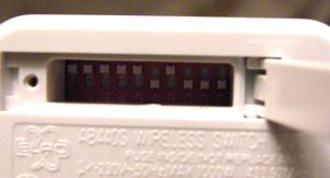
Outlets have a two-part hardware address. The first 5 bits are the same for the whole set and coincide with the address of the console. The last 5 bits are individual. The address can be changed by unscrewing the cap. On other models, the address setting may be different - see the rc-switch website .
If you are not using GSMSHIELD, but some other library, then the code will of course be different, but the principle will be the same. At certain time intervals, we check if we have unread SMS, parse them, and if a valid command came from an authorized number, we send a radio signal
Note In my case, for Seeedstudio’s Shield, it was necessary to get into GSM.cpp and change the given pins to 7 and 8.
If the sockets do not want to switch to any, you can try to receive a signal from the native console to the receiver. Rc-switch has sample code.

How can you further develop this project:
Firstly, we still have a lot of pins on the Arduino itself and on the GSM-shield. You can connect to them some sensors or devices. For example, do remote temperature monitoring or watering flowers.
Secondly, we used only SMS, and the module is able to transmit voice and GPRS. GPRS can transfer much more data. In addition, you can not hang up when you call, but, for example, take a call and give to listen to what is happening on the spot.
It is also possible that you will want to receive control SMS not from one number, but from several. In this case, I would recommend storing numbers in the address book & mash; The library has corresponding functions.
We will use ready-made radio-controlled sockets, so we do not need to solder anything. This is very cool, because it’s better not to touch 220V (beginners).
PS Yesterday was a similar topic , but was used Raspberry Pi, managed through chat. Our version is somewhat simpler and more universal, because it does not need the Internet and a smartphone, and instead of Raspberry it will be the usual Arduino.
')
We will need
Iron
- Arduino UNO or equivalent. In principle, you can and Mega.
- GSM / GPRS Shield. Any suitable. I used the shield from the Chinese Seeedstudio , because its easiest to buy from Russia.
- Transmitter 443MHz - on AliExpress a pair of receiver-transmitter costs almost 20 rubles. Mine is called FS1000A / XY-FST, where FS1000A is the transmitter.
- Controlled outlet (s) 443MHz . I took a set of AB440S of three outlet adapters with remote control in a German online store. Now, it seems, it is possible to find something similar with us - I saw it recently at Chip-i-Dip.
Soft
- Library to manage the GSM shield. Download the code from the manufacturer's website. There was no such code for my shield, so I downloaded the universal library for SIM900 GSMSHIELD
- The rc-switch library for controlling sockets.
Principle of operation
In the 433MHz range, low-power radios and remote control devices can operate without a license. On sale you can find ready-made dimmers, switches, cartridges and sockets, controlled by the remote on the radio in this frequency range. For our purposes, "intermediate" sockets-adapters are best suited: a radio-controlled device is inserted into an ordinary outlet, and the device itself is already inserted into it.
So that such sockets can be distinguished among themselves, they have an address given by DIP- or rotary switches. Due to this, you can control multiple outlets independently. Or vice versa - set them the same address so that they turn on and off at the same time.
Our scheme is elementary: Arduino receives an SMS with the command, then sends a “turn on” or “turn off” signal to the sockets using the radio module. SMS will be of the form A1B0C0, where A, B, C ... are the names of the sockets, 0 is off, 1 is on.
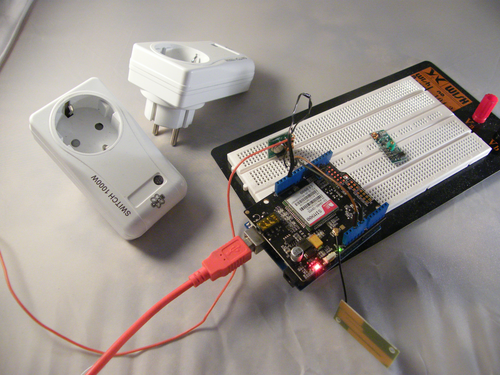
We assemble device
- We insert the sim card into the GSM-shield, and the shield into the arduin.
- Connect the transmitter's feet: GND → GND, VCC → 5V, DATA → to one of the pins, for example, 12.
- I also soldered the 15 cm postings to ANT in the corner of the transmitter handkerchiefs. But it seems to me that this is optional.
We check the GSM module
If you have not worked with GSM-shield before, I recommend to first fill in the test code (taken from here ) and check its operation.
The code sends all data from the Serial to the SoftwareSerial and back, so by connecting the shield to the SoftwareSerial, we can send commands to the modem via the Serial Monitor in the Arduino IDE.
//Serial Relay - Arduino will patch a //serial link between the computer and the GPRS Shield //at 19200 bps 8-N-1 //Computer is connected to Hardware UART //GPRS Shield is connected to the Software UART #include <SoftwareSerial.h> SoftwareSerial GPRS(7, 8); unsigned char buffer[64]; // buffer array for data recieve over serial port int count=0; // counter for buffer array void setup() { GPRS.begin(19200); // the GPRS baud rate Serial.begin(19200); // the Serial port of Arduino baud rate. } void loop() { if (GPRS.available()) // if date is comming from softwareserial port ==> data is comming from gprs shield { while(GPRS.available()) // reading data into char array { buffer[count++]=GPRS.read(); // writing data into array if(count == 64)break; } Serial.write(buffer,count); // if no data transmission ends, write buffer to hardware serial port clearBufferArray(); // call clearBufferArray function to clear the storaged data from the array count = 0; // set counter of while loop to zero } if (Serial.available()) // if data is available on hardwareserial port ==> data is comming from PC or notebook GPRS.write(Serial.read()); // write it to the GPRS shield } void clearBufferArray() // function to clear buffer array { for (int i=0; i<count;i++) { buffer[i]=NULL;} // clear all index of array with command NULL } Fill the code in Arduino, open the Serial monitor. Enter the AT command - the answer should be OK. If there is no answer, then something is wrong. Perhaps you need to change the transfer rate?
Then you can check that we registered on the network:
AT + COPS?
+COPS: 0,0,"MTS-RUS"OKI recommend lowering the speed of the UART modem. I don’t know for sure about SMS, but GPRS works exactly more reliably at low speeds - Arduinka has a small buffer and some of the information may be lost. Set the speed to 2400 baud.
AT+IPR=2400OKIf you also want to play around with the modem, I recommend using a ready java applet for the browser. Well, you can read the manual commands.
We look / change the addresses of the sockets
Outlets have a two-part hardware address. The first 5 bits are the same for the whole set and coincide with the address of the console. The last 5 bits are individual. The address can be changed by unscrewing the cap. On other models, the address setting may be different - see the rc-switch website .

Code
If you are not using GSMSHIELD, but some other library, then the code will of course be different, but the principle will be the same. At certain time intervals, we check if we have unread SMS, parse them, and if a valid command came from an authorized number, we send a radio signal
mySwitch.switchOff or mySwitch.switchOn , giving them the address of the outlet.Note In my case, for Seeedstudio’s Shield, it was necessary to get into GSM.cpp and change the given pins to 7 and 8.
/* Arduino GSM-switch example code Switch on/off radio controlled controlled outlets Author: Vladislav Ross, 2014 Contact: vladislav.ross@gmail.com You need to download: 1. rc-switch https://code.google.com/p/rc-switch/ 2. GSMSHIELD http://www.gsmlib.org/ For GSMSHIELD: * To change pins for Software Serial, use the two lines in GSM.cpp. * If you are using Mega, uncomment "#define MEGA" line in HWSerial.h * You can enable debug messages on serial port by defining DEBUG_ON */ #include "SIM900.h" #include <SoftwareSerial.h> #include "sms.h" #include "call.h" #include <RCSwitch.h> // 433MHz transmitter pin const byte RCpin = 12; char groupAddress[6] = "11111"; char smsLetters[] = "ABC"; char* deviceAddresses[] = { "10000", //A "01000", //B "00100" //C }; char adminNumber[] = "+74991356235"; //your phone number CallGSM call; SMSGSM sms; RCSwitch mySwitch = RCSwitch(); char number[20]; byte stat=0; char smsText[11]; byte position; int deviceLetterIdx = -1; byte i,j; void setup() { gsm.begin(2400); delay(10000); for(i = 1; i <= 21; i++) { sms.DeleteSMS(i); } mySwitch.enableTransmit(RCpin); }; void loop() { //hang up all incoming calls /*stat=call.CallStatus(); if(stat==CALL_INCOM_VOICE) { call.HangUp(); }*/ position = sms.IsSMSPresent(SMS_UNREAD); //get new SMS if (position) { sms.GetSMS(position, number, smsText, 10); sms.DeleteSMS(position); if(strcmp(number, adminNumber) == 0) //accept SMS only from defined number { for (i = 0; i < sizeof(smsText) - 1; i++) { if(deviceLetterIdx != -1) { //got letter, now expecting 0 or 1 if(smsText[i] == '0') { mySwitch.switchOff(groupAddress, deviceAddresses[deviceLetterIdx]); delay(500); } if(smsText[i] == '1') { mySwitch.switchOn(groupAddress, deviceAddresses[deviceLetterIdx]); delay(500); } deviceLetterIdx = -1; } else { //waiting for letter A,B,C... for(j = 0; j < sizeof(smsLetters) - 1; j++) { if(smsLetters[j] == smsText[i]) { deviceLetterIdx = j; break; } } } } } } delay(10000); }; GithubProblems?
If the sockets do not want to switch to any, you can try to receive a signal from the native console to the receiver. Rc-switch has sample code.

What's next?
How can you further develop this project:
Firstly, we still have a lot of pins on the Arduino itself and on the GSM-shield. You can connect to them some sensors or devices. For example, do remote temperature monitoring or watering flowers.
Secondly, we used only SMS, and the module is able to transmit voice and GPRS. GPRS can transfer much more data. In addition, you can not hang up when you call, but, for example, take a call and give to listen to what is happening on the spot.
It is also possible that you will want to receive control SMS not from one number, but from several. In this case, I would recommend storing numbers in the address book & mash; The library has corresponding functions.
Source: https://habr.com/ru/post/237553/
All Articles