Three-channel UART ADC on ATtiny13
Hi habr. I have long been making the UART Analog-to-Digital Converter on ATtiny13 , why do I do it on the ATtiny13 because there is, for example, the ATmega8 has 6 (for a DIP package) ports on which you can measure the ADC with the help of a multiplexer?
There are several reasons:
- ATtiny13 is cheaper;
- In ATtiny13 microcontroller resources are used more optimally;
- Dimensions;
- Power usage;
- I just wanted to.
')
Of course, many arguments can be found on my arguments, for example, when using V-USB , the ATmega8 can turn into an I / O board that does not need a UART-to-USB adapter, though you can’t argue with that, except the last.
I set myself the goal of gaining experience with the software UART on ATtiny13, and the experience as they say is invaluable. In any way it is useful for future projects.
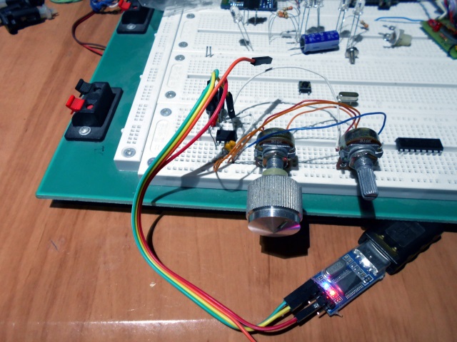
Well, I will not pull and show you how it works in the gland:
A couple of words on the scheme, by the way, here it is:
Proteus circuit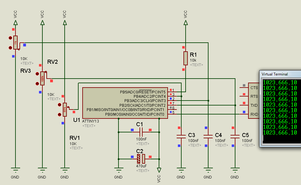
I will say right away that it would not be bad to pay attention to the power filter, I have two C1 capacitors - preferably “ceramics” and as close as possible to the legs of the MK, well, C2 is electrolytic, the second one can be set to 100 μF, but I didn’t have this under hand, found at 470 uF 10 V. It would also be not bad on the capacitor to each port of the ADC, and as close as possible to the MK. R1 is not critical, but according to the rules of "good tone" - must be present.
The data, as you could see, comes in 1023, 666 , 10 format, well, at least take it and save it in CSV format on a computer or another device that will receive this data.
By the way, the data in my case is an inexpensive USB to UART converter based on the PL2303HX chip. I tried to power the ATtiny13 from the onboard 3.3V. That on the converter, by multimeter to article 3.4V, it works, I initially thought that changing the power supply to such a high value would somehow affect the sending of data, I read the scary story somewhere, heat it up a couple of degrees , cool down and everything, goodbye adequate data ... Nothing of the kind, cooled with ice, slightly heated with a cigarette lighter (without fanaticism) - everything works fine, I did not observe any losses.
A few words about the code - the code was written in the BASCOM-AVR environment on Basic, so I bring to your attention my writing code I spent about 4-5 hours, since I had not met Basic before, but this time was spent not just to write code, but also to deal with the features of BASCOM-AVR, debugging and all that.
Code
Samples Alias 64 ' #define ' $regfile = "attiny13.dat" ' $crystal = 1200000 $hwstack = 16 $swstack = 16 $framesize = 16 '$noramclear Open "comb.0:9600,8,n,1" For Output As #1 ' UART, 9600 ' PB0 TXD, RXD Config Adc = Single , Prescaler = Auto , Reference = Avcc ' , Vcc Start Adc ' ' Adc - : Single - , ' Free ( ) ' Prescaler = 128 - ' ( 2,4,8,16,32,64 Auto). ' Auto, ' Reference – . Aref – , ' Avcc – , Internal – 1,1 . Declare Function Adc_get(byval Adc_port As Byte) As Word ' ' "Samples" Do ' Print #1 , Adc_get(1) ; "," ; Adc_get(2) ; "," ; Adc_get(3) ' *,*,* Loop ' Function Adc_get(byval Adc_port As Byte ) As Word ' Word . 65535 Dim Temp_result As Word ' Dim Adc_cycles As Byte ' Temp_result = 0 For Adc_cycles = 1 To Samples Temp_result = Temp_result + Getadc(adc_port) Next Temp_result = Temp_result / Samples Adc_get = Temp_result ' Temp_result End Function What does the code do? First, a software UART is created; here it is done very simply; we set the necessary parameters, port, speed, and so on; . Why did I choose 64 instead of for example 42 or 108? Well, because 1023 * 64 is equal to 65 472, and for the type of Word that I used for the buffer, the maximum value that a variable can accept is 65,535, this number is the largest number represented as a two-byte unsigned word if you add another sample the variable will simply be reset if the ADC returns 1023. For some reason, Long had problems, and I personally have 64 samples, I’ll show you how it works on the graph below. Well, then the results are displayed in the UART.
As you can see, noise is of course present, even despite the fact that the average value of 64 samples is displayed, judging by the datasheet noise at ± 2 LSB is the norm, I have 1 LSB noise.
Screen software
As you can see, ATtiny13 sends values 15-16 times per second, which I think is not bad considering that this is a software UART and Tin does 64 measurements per port, and there are three of them.
MK consumes the following current:
Power 5 V - 2.71 mA
Power 3.3 V 1.75 mA
A few words about programming - as I said in the video, the frequency of the MK is 1.2 MHz, all the fyuzy by default, as in my previous topic Music door bell in the style of Star Wars .
Here are the fusions from the fusion calculator :
Fuses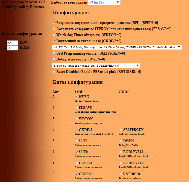
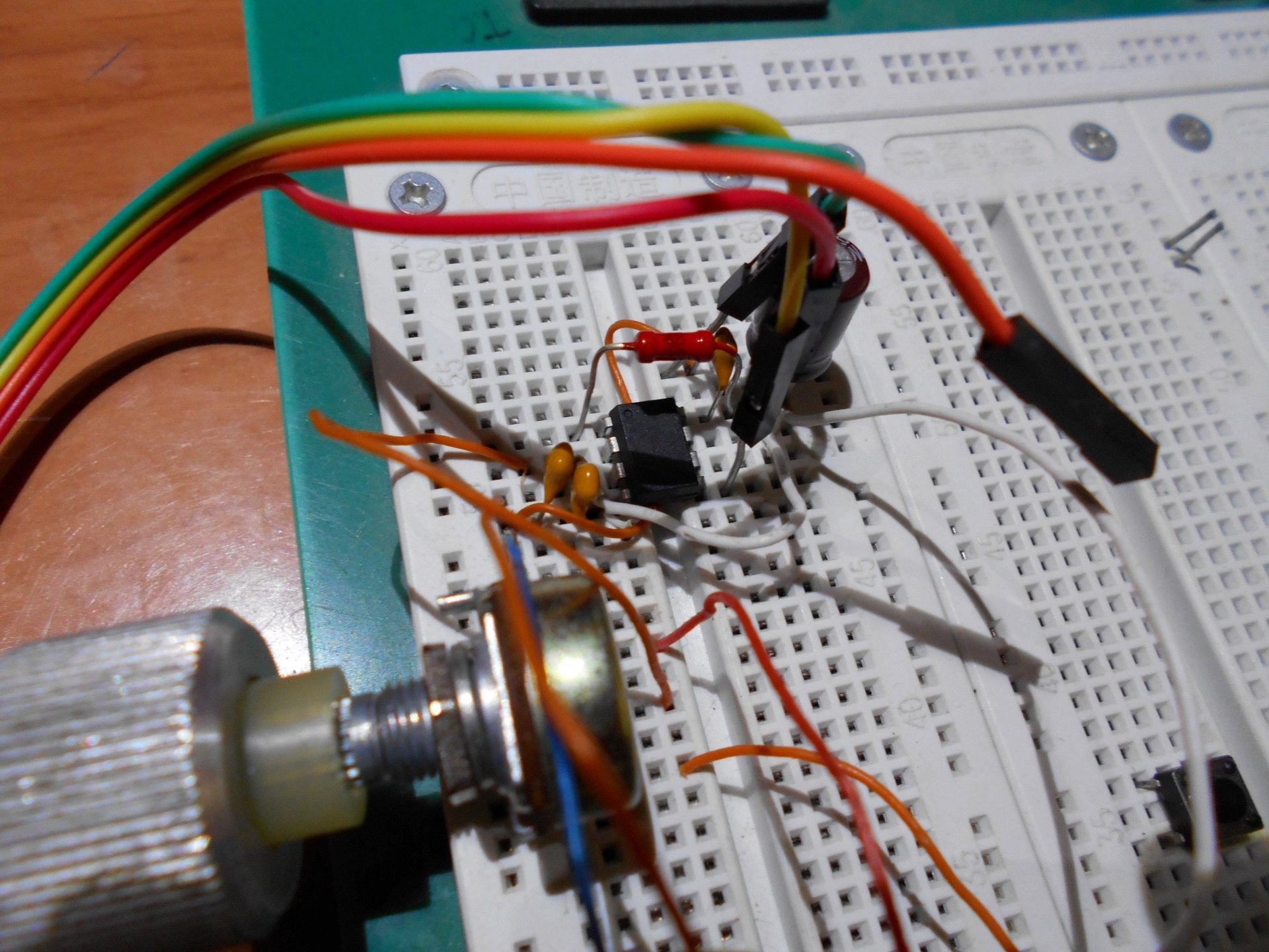
Well, at the end of a couple of pictures from different angles:
A small photo shoot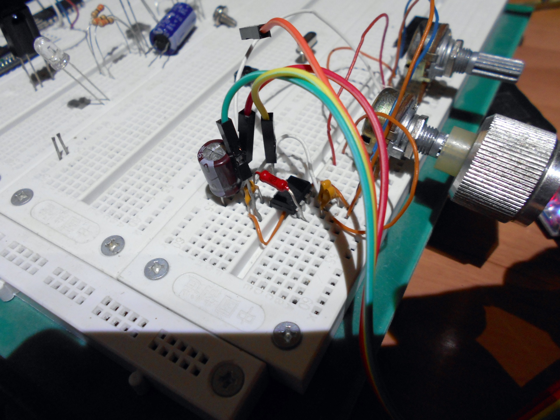
References:
Wiring Alternative for Arduino - BASCOM-AVR
Software that made graphics - Serial oscilloscope
Archive with source code, hex-file and scheme in Proteus 7 Professional
All my publications .
Source: https://habr.com/ru/post/237543/
All Articles