Development and debugging of UEFI-drivers on Intel Galileo, part 2: preparing a springboard
Hello, dear habrovchane.
The survey in the first part showed that the topic of developing UEFI drivers is quite interesting to the community, so I’m starting to write further parts of this cycle. This discussion will focus on preparing the Intel Galileo board for the work needed and desired hardware and software, building and installing BSP . The result is an inexpensive hardware platform suitable for hardware debugging of UEFI drivers and available to any enthusiast.

Entry and Disclaimer
By tradition, it should be mentioned that you use all of the following information at your own peril and risk; the author is not responsible for any loss of performance of the board, time, mood, and / or faith in humanity. Everything described is obtained from open sources, a list of which is given at the end of this article, and this publication cannot be considered a violation of the NDA on my part.
Cooking iron
The board itself
First of all, you need to get some sort of Intel Galileo board. It doesn't matter if it is of the first or second generation (they are no different from the UEFI and software side), the main thing is that you can connect the power supply and the UART converter (mandatory), as well as the JTAG debugger and ISP programmer (preferably) . This board came to me in the context of exploring the capabilities and prospects of Quark SoC by our company and was obtained directly from the German representative of Intel. For an ordinary person, the easiest way is to simply buy this board.UART
To connect to Galileo Gen 1 via UART, you will need an AJ-COM cable, which is easiest to make yourself using this scheme:
If you do not have a COM port on your PC, you will have to use a COM-USB converter, which are many on the market, and they are inexpensive, and it is not a big problem to make such a converter from PL23xx / FT232 + MAX232 on your own. In my case, kind people from Intel put an AJ-COM cable and a COM-USB converter on the base of PL2303 into the box with Galileo.
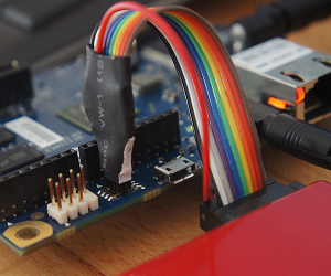
User feedback and operating experience of Galileo Gen1 led Intel engineers to the fact that Gen 2 had a 3.5 "Stereojack and MAX232 chip, which had previously shifted compatibility levels with a COM port, they were replaced with a comb compatible with USB-TTL cables manufactured by FTDI and having this pinout:

Thus, for connecting to the UART port on Gen 2, there is enough cable similar to TTL-232R-3V3 , which can again be made independently from the above-mentioned PL23xx / FT232. Such a replacement is beneficial for both Intel (MAX232 was thrown out of the scheme), and for users who now need only one cable instead of two. Moreover, almost everyone who is at least a little familiar with the world of DIY electronics already has a USB-TTL converter.
JTAG
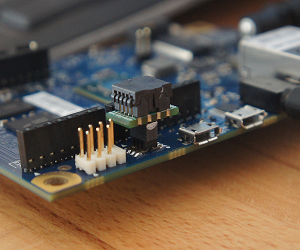
As I wrote in the previous part, Galileo is still the only x86 CPU based card I know, on which the JTAG TAP port is available immediately, without the need to connect expensive converters like Intel XDP. On the one hand, this opens up very wide possibilities for hardware debugging, and on the other hand, for almost all cases of debugging UEFI drivers, debugging messages via UART are sufficient, for which neither JTAG, nor additional software, only the terminal, only hardcore are needed. On the other hand, to miss this opportunity is without grace, so removing the debugger connection is also worth describing.As a JTAG connector on Galileo, a 10-pin connector with a 1.27 mm pitch is used, which you simply cannot connect to - a small, contagious one. Intel proposes to use such an adapter for a “normal” 20-pin JTAG connector, and this is a good offer, but for those who can solder, I have a better offer: just solder the five wires to the labeled pins on the back of the connector, and on the other hand side to solder compatible in your JTAG-debugger connector or on the BLS-tip on each wire. From the side of the board, it will look something like this (I apologize for the unwashed flux):

Now, no adapters are needed, and you can connect the board to any debugger from the list of supported OpenOCD. At Intel, debugging performance on Galileo was tested with TinCanTools FLYSWATTER2 and Olimex ARM-USB-OCD-H , but both of these debuggers are an ordinary FT2232H in a beautiful case, so you can use any MFSE-based FTDI 232 chip to debug on Galileo. Learn more about debuggers and debugging in one of the following parts.
')
ISP
Errors in the development and debugging of UEFI-drivers often lead to the fact that the board stops loading, and you have to use the recovery of the SPI-chip content using a recovery image or an external programmer. In addition, the development implies a constant update of the firmware, and each time updating the firmware with the help of the standard utility CapsuleApp.efi takes a long time and it instantly bothers you. That is why it makes sense to connect a programmer to Galileo and sew them. Unfortunately, attempts to use the FT232H board in conjunction with the flashrom utility as an ISP programmer on this board have not been successful yet, and until this problem is solved, I will use the Samedisk ZC2511 programmer . Intel, in turn, offers to use the Dediprog SF100 , which is also quite suitable. If you already have a SPI programmer, you can try to connect it to the ISP connector located in the right upper part of the front side of the board according to the pinout below:
Lyrical digression or some SPI emulators
In fact, ISP is not the pinnacle of progress, and for professional firmware development, SPI emulators are used instead of SPI programmers, which reduce the firmware update time to 1-2 seconds. For an ordinary person, they are not available due to the high price (about $ 500-700 per piece), so I will not dwell on them at all. We use the Samedisk ZC25128 emulator capable of emulating SPI chips from various manufacturers with capacities up to 128 Mbps. From the point of view of the OS, the emulator looks like an ordinary USB flash drive, and you can update the firmware by simply copying the file with it. So far, I have only one case in my memory (Intel CRB for Bay Trail), when the system refused to boot from the emulator, so I have to admit that the solution has the right to life. It is surprising only a rarity (and, in connection with it, high cost) of similar devices, because now every second microcontroller has several hardware SPI channels and nothing prevents the production of emulators.For compatibility with the emulator, I modified my Galileo Gen 1 board by replacing the SPI chip with a special connector, to which either the emulator or the SPI chip in the ZIF bed is connected. It looks like this:
Now, finally, the hardware is ready, and you can start preparing the software.

We prepare software
Assembly platform
For Galileo, there are two fundamentally different sets of software: BSP and Arduino Software. The first set is needed to build both the UEFI firmware and the one offered by Intel as the base version of Yocto Linux in several versions, the most popular of which are two - galileo-spi and galileo-full. The first is a minimal Linux system that starts directly from the SPI chip and is able to perform Arduino-sketches, the second one already looks more like a normal Linux, but you need to load it from an SD card. There is a small problem with this type of boot: most of the Gen1 motherboards require firmware upgrades so that at least something is started from the SD card, so the launch of an already prepared Intel image is impossible out of the box.Compatibility with Arduino in this article does not interest us, so from the entire software bundle we need only an archive with BSP, usually called Board_Support_Package_Sources_for_Intel_Quark_vX.YZTzip , at the moment its latest version is 1.0.1.7. Intel offers a furiously huge choice of platforms for building BSPs in the amount of exactly one piece - Ubuntu 12.04 x64. Of course, you can try to build from another Linux distribution (I tried from Ubuntu 14.04, the minimum image is collected, full is no longer) or even from OSX or Windows, but it is much easier for me to install the necessary version on a virtual machine and run the assembly from her I will not dwell on the installation of Ubuntu, I will only indicate the list of packages that will need to be installed at every stage of the BSP assembly.
BSP assembly
Zero step
So, you have Ubuntu 12.04 x64 installed, updated and downloaded, the archive from the latest BSP is downloaded and unpacked, for definiteness, in ~ / Galileo /, you have an Internet connection and you are ready to spend some time.Before you start building, you must install the following packages: build-essential and gcc-multilib . They are required at all stages of assembly. I also recommend to open a new terminal in ~ / Galileo / for each step in order to prevent possible conflicts of assembly environments created at each step.
Build UEFI
To build UEFI, you need to install the subversion , uuid-dev, and iasl packages . After that, you need to unpack the Quark_EDKII_vX.YZtar.gz archive, go to the Quark_EDKII_vX.YZ directory created when unpacking and run the svn_setup.py script first , and then the svn update command that will load the necessary EFI Development Kit for it. After the download is completed, you need to execute the command ./quarkbuild.sh -d32 GCC46 QuarkPlatfrom , which will start the assembly of the debugging version of UEFI (d32 key) using GCC 4.6 (in Ubuntu 12.04 just this) for the Quark SoC platform (which Galileo is). After the build is completed, the QUARK.fd file will be located in the Build / QuarkPlatfrom / DEBUG_GCC46 / FV / directory - an incomplete firmware image that you will need in the next section, and in the Applications subdirectory - the CapsuleApp.efi utility used to update the UEFI Shell firmware, which will have to use if you don't have a programmer.Build grub
As the default bootloader for the BDS phase on this board, Intel suggests using a fairly modified GRUB v1. It may not be compiled if you intend to create even a minimal assembly of Yocto Linux, but in our case you need to build it. You will need to install the gnu-efi , autoconf , libtool, and git packages. As usual, unpack the archive with GRUB, go to the directory created after unpacking and execute the gitsetup.py script, then go to the work subdirectory and execute the commands autoreconf --install , export CC4GRUB = 'gcc -m32 -march = i586 -fno-stack- protector ' , export GNUEFI_LIBDIR = / usr / lib32 , CC = "$ {CC4GRUB}" ./configure-quark.sh . Do not rush to do make , you first need to correct the error, if your version has one. The fact is that the collectors forgot to put the crt0-efi.S file in work / efi / ia32 /, and without it you can’t compile GRUB (this is a startup code), so you need to download it (for example, from here ), rename it correctly, copy it to above directory, and then with a clear conscience to run the command make . As a result, in work / efi /, the grub.efi file we need will be found.Building a minimal Yocto Linux image
To build a minimal OS image, which will then be placed in the SPI chip, you need to install the diffstat , texinfo , gawk and chrpath packages , and if you do not perform the previous step, then git . Unpack the meta-clanton_vX.YZtar.gz archive, go to the created folder and execute the setup.sh script, now you have to wait a bit. After waiting for the download of the build scripts, execute the commands source poky / oe-init-build-env yocto_build and bitbake image-spi-galileo , after which the rather lengthy process of downloading and assembling Yocto from the source code will begin. To build a minimum image, you need about 2 GB of disk space, and building the most complete image requires about 35 GB and runs for almost 7 hours on my Core i5-2500K with 8 GB of RAM and SSD. If suddenly it will be interesting to someone, I will write a separate article about assembling such an image, because they have enough of their underwater rakes, which would be superfluous here. In general, I propose to relax at this place and look at the course of the assembly, which anyBuild all of the above into one file
The OS image is ready, and you can put all the components together. To do this, unpack the sysimage and spi-flash-tools archives and go to the sysimage_vX.YZ / sysimage.CP-8M-debug / directory, in which, besides everything else, there is a layout.conf file. Open it in your favorite text editor and correct all paths and file names to the correct ones, replacing “PLAIN / DEBUG_GCC” with “DEBUG_GCC46”, “image-spi-clanton.cpio.lzma” with “image-spi-galileo-clanton.cpio. lzma ”and adding the correct version number to“ meta-clanton ”and“ Quark_EDKII ”, after which do not forget to save the changes. Then execute the command ../../spi-flash-tools_vX.YZ/Makefile , as a result, Flash-missingPDAT.bin, Flash-missingPDAT.cap and FVMAIN.fv files will be created in the sysimage.CP-8M-debug directory. The latter is used as a recovery image, the second can be copied to a microSD card and you can update your Galileo firmware using CapsuleApp.efi from UEFI Shell, and one more step, the last one, is needed to finish the first one.Adding Platfrom Data to Flash-missingPDAT.bin
The last step is to add platform dependent settings. To do this, go to the spi-flash-tools_vX.YZ / platform-data / directory, open the sample-platfrom-data.ini file in your favorite editor and fix the value in it in the [Platfrom Type] section data.value to 6 for Gen1 or 8 for Gen 2, in [Mrc Params] data.value at MRC / kipsbay-fabD.v1.bin (Gen 1) or MRC / GalileoGen2.bin (Gen 2), comment out the example with data.type = hex.string in the same section and change in the [MAC address 0] section the value of data.value to the address printed on the label on the Ethernet connector of the board, [MAC address 1] on Galileo can be not changed. After that, you need to run the command ./platform-data-patch.py -p sample-platfrom-data.ini -i ../../sysimage_vX.YZ/sysimage.CP-8M-debug/Flash-missingPDAT.bin , which Finally, it will create a Flash + PlatfromData.bin file, ready for firmware by the programmer.
Health check
We flash the image obtained at the previous step, connect the UART board to the PC, launch the favorite terminal (for Windows, I can advise Putty / Kitty or TeraTerm), connect to the corresponding COM port with settings of 115200 baud, data - 8 bits, stop - 1 bit, parity and flow control are disabled, and we connect power to Galileo.If you see a stream of debug UEFI messages, like the one in the image below, everything is done correctly. If not - we double-check it still a couple of times, as they say, UMVR .


Conclusion and future plans
At the end of this part of the article, we obtained a hardware platform prepared and tested for operability, which can be successfully used to debug self-written UEFI drivers, if we integrate their assembly into the UEFI image in the first step. In the next part, I will try to show how you can significantly simplify and speed up the assembly process, exactly how your drivers are integrated into the EDK code base and how to debug them using the UART. On JTAG debugging in Eclipse using OpenOCD and GDB is planned to talk separately.By the first part, by the way, there were practically no comments, I hope they will be to this one. Thank you for your attention and see you in the following sections.

Information sources
Intel Quark SoC X1000 Board Support Package (BSP) Build and Software User GuideSource Level Debug using OpenOCD / GDB / Eclipse on Intel Quark SoC X1000
Intel Galileo Gen1 Schematics
Intel Galileo Gen2 Schematics
FTDI TTL to USB Serial Converter Range of Cables Datasheet
Intel Embedded Community
Source: https://habr.com/ru/post/237183/
All Articles