Tree (dotted) model support in 3D printing
The article describes the personal experience of creating and applying tree-like supports when printing complex objects on a 3D printer.
Typically, support is created when 3D printing in software for generating gcode, for example in Cura, right before generating gcode. The easiest way to print a pyramid-shaped object on a 3D printer. Then each next layer falls on the previous one and does not hang over the empty space. Supports allow you to print overhanging parts of objects, but standard supports are not always optimal in terms of plastic consumption and the simplicity of their subsequent separation from the object itself, so in this article I will describe my personal experience in creating and using tree supports.
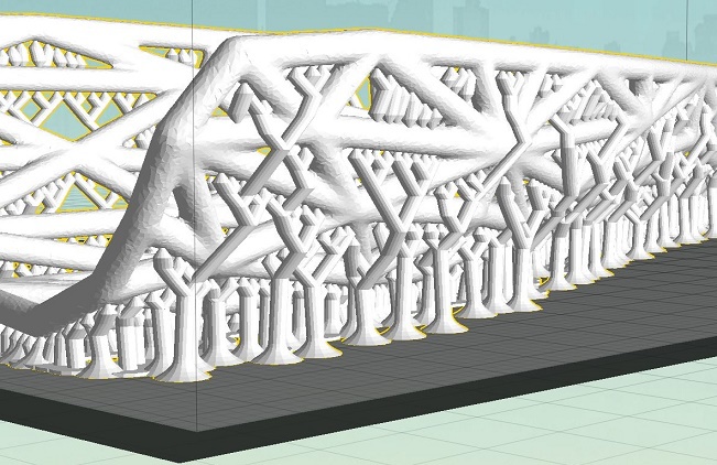
Supports are created by a graphics program, in the case of MeshMixer in automatic mode.
For a program to generate code for a 3D printer, the result of MeshMixer will be a continuation of the model itself.
You can create manually or edit already generated (just).
')
1. Full control over the process of creating supports.
2. Easy to clean model.
3. Minor traces. With a successful setup, there are no.
4. Savings plastic in certain cases.
5. Does not need the Raft backing.
1. The probability of breakage of support is relatively high.
2. Requires skills to create supports (tasks printed for the first time, do not leave unsupervised. So you can save plastic on unsuccessful results).
3. Support for horizontal planes requires a large number of points of support, which can negate the savings on plastic.
1. A new feature appears in printers, allowing you to skip over supports without breaking them.
2. The Slic3r code generator does the same by ordering the movement of the extruder, bypassing the one already printed in the printing plane, without resorting to height movement.
The question is not unambiguous, and depends on both the model and the material.
The main trends, which at the moment managed to highlight:
1. By material : PLA support on the basis of all the other factors will show a better result than in the case of ABS. Due to the properties of this plastic, the drop in “its strength” of the material between the layers is compensated by flexibility. But if you make the supports too thick, they will break guaranteed. Also, PLA is peculiar to buoyancy, due to which the part is wrapped in a thin web of such threads, and the previously lost support can grow further from the moment of breaking, relying on these fibers from neighboring supports.
2. According to the heights of the supports : The greater the height, the greater the effect of the tree support can be obtained. From 6 mm the effect grows from “nothing” with increasing dependence to “very much”.
After a height of 35 mm, it is better to strengthen the generated supports yourself in the program itself with additional trunks.
3. On the slope from the vertical : The smaller the angle (i.e., the less hanging), the greater the effect. And in the case of horizontal (for example, ceilings), tree-like point supports are inferior to “linear support” (standard supports), since the printer prefers to build “bridges” between two lines rather than a group of support points.
4. On surface details : Spot, it’s also tree support is preferable for a large number of parts (fingers, frames, grids).
5. By proportions : The ratio of height to width and plane of the base. Pinpoint tree support is preferred in cases of height predominance.
Although most of the comments are speculative, they should be sifted through the mind, constantly gaining typing experience, and analyze the degree of their influence on the result, having visually set out directions of dependencies and trends.
Tree support is easy to create in any graphics program independently and without generation by the program. But programmatically it is implemented in Meshmixer. www.meshmixer.com/index.html
The function itself in the program is implemented in two different modes: with the presence of the “[2] Convert to Solid” key or without it.
Using the Overhands function, you can immediately set up a “tree” by analyzing the model in all respects for compatibility with 3D printing.

And you can go to the “Model location mode in the printer workspace” and create support there.
In both cases, regulatory authorities are more than enough. The influence of some of them on the result has not yet been determined empirically, clearly and conclusively.
But some regulators make it possible to speed up the processes of support generation and preparation for printing.
The first thing to reduce is the number of sides to a minimum = 3, then the supports will become triangular and the experiments will go faster.
This is done in the expanding menu “Advanced Support”. The value is “Post side”.
Creation - the generation of supports occurs only after pressing the [1] button. And new parameters will be applied only after deleting the old ones and generating new ones.
Multiple experiments can give a fairly clear idea of the change in the proposed parameters.
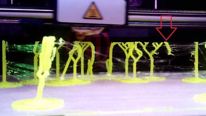
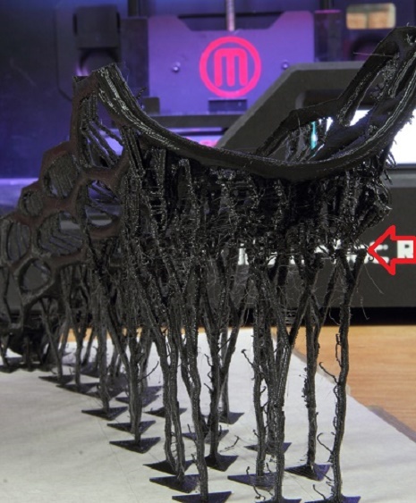
Such experiments overlook only the fact that the printer itself is not physically able to print: these are the sharp ends of the supports. The model will simply hang, and the tips of the supports will not reach the target surface.
In more detail, it makes sense to raise the entire model above the table with supports, this will make it possible to compensate for temperature shrinkage due to the flexibility of the supports. The part, having cooled down, will shrink and will not detach from the table in the process of printing.
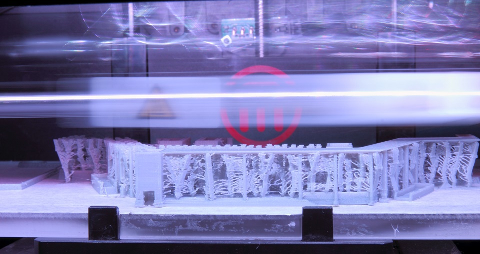
This effect is clearly pronounced, mainly in hollow and frame (wireframe) models.
This method is a simple, but flexible in the settings tool that expands the possibilities of printing, saving plastic and time for cleaning parts. With the prospect of development. Provides the ability to combine.
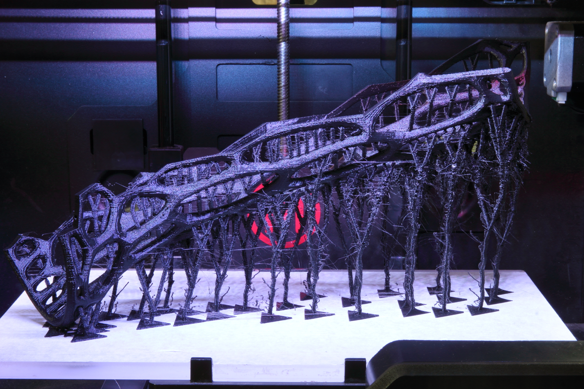
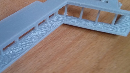
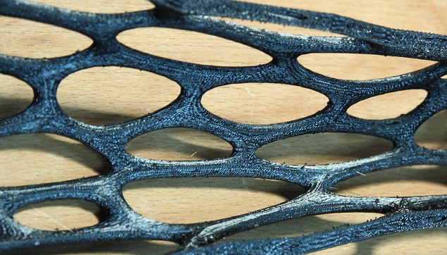
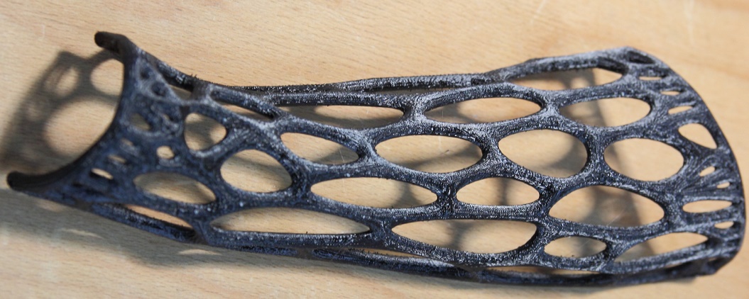
PS Anticipating the issue of the model in the photo. This is part of the plastic plaster for one of the internal campus Navigator projects.
Typically, support is created when 3D printing in software for generating gcode, for example in Cura, right before generating gcode. The easiest way to print a pyramid-shaped object on a 3D printer. Then each next layer falls on the previous one and does not hang over the empty space. Supports allow you to print overhanging parts of objects, but standard supports are not always optimal in terms of plastic consumption and the simplicity of their subsequent separation from the object itself, so in this article I will describe my personal experience in creating and using tree supports.
Creation of tree supports
Supports are created by a graphics program, in the case of MeshMixer in automatic mode.
For a program to generate code for a 3D printer, the result of MeshMixer will be a continuation of the model itself.
You can create manually or edit already generated (just).
')
Tree Support Benefits
1. Full control over the process of creating supports.
2. Easy to clean model.
3. Minor traces. With a successful setup, there are no.
4. Savings plastic in certain cases.
5. Does not need the Raft backing.
The drawbacks of tree support
1. The probability of breakage of support is relatively high.
2. Requires skills to create supports (tasks printed for the first time, do not leave unsupervised. So you can save plastic on unsuccessful results).
3. Support for horizontal planes requires a large number of points of support, which can negate the savings on plastic.
Prospects for tree support
1. A new feature appears in printers, allowing you to skip over supports without breaking them.
2. The Slic3r code generator does the same by ordering the movement of the extruder, bypassing the one already printed in the printing plane, without resorting to height movement.
Areas of use
The question is not unambiguous, and depends on both the model and the material.
The main trends, which at the moment managed to highlight:
1. By material : PLA support on the basis of all the other factors will show a better result than in the case of ABS. Due to the properties of this plastic, the drop in “its strength” of the material between the layers is compensated by flexibility. But if you make the supports too thick, they will break guaranteed. Also, PLA is peculiar to buoyancy, due to which the part is wrapped in a thin web of such threads, and the previously lost support can grow further from the moment of breaking, relying on these fibers from neighboring supports.
2. According to the heights of the supports : The greater the height, the greater the effect of the tree support can be obtained. From 6 mm the effect grows from “nothing” with increasing dependence to “very much”.
After a height of 35 mm, it is better to strengthen the generated supports yourself in the program itself with additional trunks.
3. On the slope from the vertical : The smaller the angle (i.e., the less hanging), the greater the effect. And in the case of horizontal (for example, ceilings), tree-like point supports are inferior to “linear support” (standard supports), since the printer prefers to build “bridges” between two lines rather than a group of support points.
4. On surface details : Spot, it’s also tree support is preferable for a large number of parts (fingers, frames, grids).
5. By proportions : The ratio of height to width and plane of the base. Pinpoint tree support is preferred in cases of height predominance.
Although most of the comments are speculative, they should be sifted through the mind, constantly gaining typing experience, and analyze the degree of their influence on the result, having visually set out directions of dependencies and trends.
Creation of tree supports
Tree support is easy to create in any graphics program independently and without generation by the program. But programmatically it is implemented in Meshmixer. www.meshmixer.com/index.html
The function itself in the program is implemented in two different modes: with the presence of the “[2] Convert to Solid” key or without it.
Using the Overhands function, you can immediately set up a “tree” by analyzing the model in all respects for compatibility with 3D printing.
And you can go to the “Model location mode in the printer workspace” and create support there.
In both cases, regulatory authorities are more than enough. The influence of some of them on the result has not yet been determined empirically, clearly and conclusively.
But some regulators make it possible to speed up the processes of support generation and preparation for printing.
The first thing to reduce is the number of sides to a minimum = 3, then the supports will become triangular and the experiments will go faster.
This is done in the expanding menu “Advanced Support”. The value is “Post side”.
Creation - the generation of supports occurs only after pressing the [1] button. And new parameters will be applied only after deleting the old ones and generating new ones.
Multiple experiments can give a fairly clear idea of the change in the proposed parameters.
Such experiments overlook only the fact that the printer itself is not physically able to print: these are the sharp ends of the supports. The model will simply hang, and the tips of the supports will not reach the target surface.
In more detail, it makes sense to raise the entire model above the table with supports, this will make it possible to compensate for temperature shrinkage due to the flexibility of the supports. The part, having cooled down, will shrink and will not detach from the table in the process of printing.
This effect is clearly pronounced, mainly in hollow and frame (wireframe) models.
Conclusion
This method is a simple, but flexible in the settings tool that expands the possibilities of printing, saving plastic and time for cleaning parts. With the prospect of development. Provides the ability to combine.
PS Anticipating the issue of the model in the photo. This is part of the plastic plaster for one of the internal campus Navigator projects.
Source: https://habr.com/ru/post/236913/
All Articles