Linux: buttons, LEDs and GPIO

Introduction
Starting from version 2.6.26 (it seems), Linux has a standard interface for working with GPIO via sysfs. In the original, you can read about it in [LGPIO00]. I will try to retell in my own words the contents of this document.
The main point of working with GPIO is the / sys / class / gpio directory . If you look into it, you will see two files: export and unexport . Immediately after booting the system, all GPIO lines belong to the kernel, and using them in your programs just won't work. For this, the GPIO line must be exported by writing its number to the export file. For example, the command:
echo 8 > /sys/class/gpio/export tells the kernel that we want to use GPIO8. The carriage return '\ n' and the line end character '\ 0' are optional: C code: write(fd, “8”, 1); - will work the same way.The line number depends on the hardware platform used and the driver implementation. It is clear that the numbering should be unique for each output GPIO. It is no secret that on some SoC there are several GPIO ports (GPIOA, GPIOB, etc.), therefore, how exactly the numbers of the lines are distributed need to be specified in each case separately. The most obvious and simplest is such a distribution: there are two GPIO ports with 32 lines each, while the first port has line numbering from 0 to 31, and the second has 32 to 63, etc.
It should be noted that in some modern SoCs, there are more peripheral devices on the chip than the outputs on the microchip can be allowed. Therefore, some of the pins are multiplexed between different peripherals. As a result, some GPIO lines may already be involved in the current system configuration by an LCD display port, for example, or a USB port. You will most likely not be able to use such lines.
')
Output: connect the LED

Suppose we found a free GPIO port pin on a printed circuit board and want to hang a LED on it. Some sort of shamanism, we establish that it has number 16. Now, you can try to get access to this line:
echo 16 > /sys/class/gpio/export . If successful, a new directory will appear in / sys / class / gpio : gpio16 .Looking into this directory you can see that to work with a separate line of GPIO Linux provides us with an interface consisting of the following files: direction , value , edge and active_low . Now we are interested in only two of them: direction and value .
- direction - determines the direction of the line: is it an input or an output. To set up a line for input, you need to write the word 'in' to the file, and if the output is 'out'.
- value - allows you to read the value on the line if it is an input, or set the value if it is an output. The value in value can take a text '0' or '1'. Note: '0' and '1' are exactly ASCII characters, not numbers.
Let's go back to our LED. The following code on the shell will light the LED and extinguish it in a second.
# exporting and tuning GPIO line echo 16 > /sys/class/gpio/export echo out > /sys/class/gpio/gpio16/direction # switch GPIO#16 on echo 1 > /sys/class/gpio/gpio16/value # sleep 1 second sleep 1 # switch GPIO#16 off echo 0 > /sys/class/gpio/gpio16/value Now let's look at the active_low file. It determines the level of the active signal — that is, which voltage will correspond to a logical zero, and which voltage to a logical one.
By default, the logical unit (high level) is the presence of some voltage at the output (depends on the type of SoC'a, but usually it is + 3.3V), and zero (low level) is the absence of voltage (short circuit to ground). However, this is not always convenient, since some signals can be inverted. For example, the CS (Chip Select) signal manufacturers like to make the chip so that the chip becomes active when there is no voltage on the corresponding output, and it stops responding to external signals if the voltage is applied. To control this setting, the characters '0' - false or '1' - true must be written to the active_low file, depending on whether we want to invert the active signal or not. By default there is a '0'.
Login: connect button
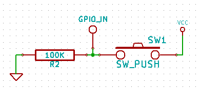
So, let's think up a button as input. The scheme might look like this:
How to configure the GPIO input is already mentioned above. You can read the current value from the file value . Just take and read. You can even use cat. Naturally, the read value depends on the active_low setting, and by default, the ASCII character is '1', if there is voltage at the output, otherwise - we get '0'.
Note that for CMOS (or something is being used now), a pin hanging in the air will most likely give a logical unit (but not necessarily, since the state is undefined and depends on the presence of a charge based on the input transistor), and if we want to get zero, then you need to connect it to the ground.
Well, now we can find out if a button is pressed or not, simply by reading the value from value. But is it convenient? Most likely no. We will have to constantly, with a certain frequency, read the current value (this technology is called polling) to determine the moment when the button is pressed. The extra work is a waste of resources. Most SoC manufacturers supply their GPIO with an interrupt controller, which generates an interrupt for all sorts of different situations: level change, level setting to high or low. Is it possible to somehow use it through sysfs? Documentation, reports that it is possible. To do this, we need to write one of the following values to the edge file: none , rising , rising , or both . Here: none - disable tracking of the state of the incoming line; rising and falling - we track the transition from inactive to active and from active to inactive, respectively; both - react to any change in state.
The instruction states that it is only necessary to set one of these values (except for none ), so immediately using the function poll () or select () you can determine whether the state of the line has changed. In case the state has not changed, the read () call for the value file should be blocked. However, there is a subtlety. If you open the value file and try to set poll () on it, you will get that the reading will not be blocked, regardless of whether the state of the line has changed or not.
The authors of the GPIO subsystem apparently wanted
cat value always work, regardless of what is written in the edge file, so the first reading will never be blocked. In principle, this is logical: in order to track changes, you must first determine the initial state. However, I had to spend almost two hours, and only in some abandoned forum I found an assumption why poll () does not work and what can be done for this.I opened the value file for each reading and was very surprised why the lock was not happening. It turned out that the file needs to be opened once for the entire session of tracking the line, reading the initial value from it and only then subsequent read operations will be blocked until the event specified in the edge appears. And here, too, there is one subtlety: the values from the value file are read only at offset 0, while a call to the read () function changes the read position. Therefore, before calling read (), you need to reset the read position with lseek (). In Linux documentation, these moments are somehow bypassed.
Here is what GPIO reading will look like using edge events:
// set edge event on specific gpio_line int gpio_edge_set(int n, const char *edge_str) { char filename[PATH_MAX]; FILE *file; snprintf(filename, sizeof(filename), "/sys/class/gpio/gpio%d/edge", n); file = fopen(filename, "w"); if (file == NULL) return -1; fprintf(file, "%s\n", edge_str); fclose(file); return 0; } // set GPIO line polling mode int gpio_poll(int n) { char filename[PATH_MAX]; int fd; char c; int err; snprintf(filename, sizeof(filename), "/sys/class/gpio/gpio%d/value", n); fd = open(filename, O_RDONLY); if (fd < 0) return -1; read(fd, &c, sizeof(c)); return fd; } // get GPIO line value int gpio_get(int fd, int timeout) { struct pollfd pollfd[1]; char c; int err; pollfd[0].fd = fd; pollfd[0].events = POLLPRI | POLLERR; pollfd[0].revents = 0; err = poll(pollfd, 1, timeout); if(err != 1) return -1; lseek(fd, 0, SEEK_SET); err = read(fd, &c, sizeof(c)); if(err != 1) return -1; return c - '0'; } Conclusion
So, what we have: we can use the GPIO line for output and input, and even with minimal resources, track changes on the line. The only thing we missed is the uevent file. To be honest, I really did not understand what it was and what it was for. Usually, uvent is the interface for the hotplug service, which, in particular, is used by the udev daemon. It seems that in openWRT udev you can configure it so that when the level changes on the line, some application will run. However, I’m not sure whether this is done by a regular udev or whether it had to be patched accordingly.
Is this all what a GPIO driver is capable of? Of course no. As mentioned above: the GPIO interface in sysfs appeared relatively recently, and before that it was used exclusively by the kernel as a driver for some physical bus. You can connect it to this bus, for example, SPI or I2C, you can make it be part of another hardware bus (for example, the ChipSelect line on the same hardware SPI), or even just set the LED and keyboard drivers on it. However, the description of these features is beyond the scope of this article.
Bibliography
LGPIO00 :, Documentation / gpio.txt,
Source: https://habr.com/ru/post/236251/
All Articles