My contribution to copterostroenie
I want to share with the habrasoobshchestvom their experiences in this area. In particular, I give open access to the frame I developed, the backlight module and all the knowledge that I gained in the process of building my vehicle.
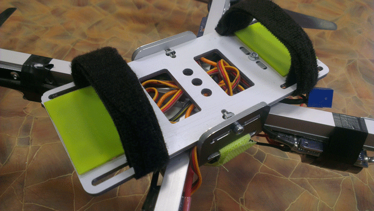
Now my copter looks like this:
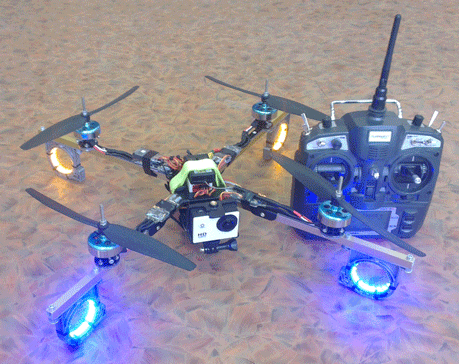
I built my kopter in pair with my younger brother and I had the main goal to carry it away with electronics. I had no desire to develop mathematical algorithms from scratch. We just, like many, took ready-made elements and put everything together. We took the DJI NAZA flight controller with the Turnigy 9x radio control equipment as a basis. On our own, we developed only the frame and the navigation light control unit which we will talk about.
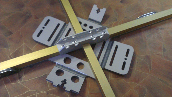
The simplest solution is to twist a cross from the aluminum profile. For the connection, we used a fee, which concurrently became a power distributor:
')

We even attached a little protection to the flight controller to it. With this frame we flew for the first time, but there was little pleasure. The screws constantly broke, it was all crooked and poorly thought out, and in the end the power supply on one of the regulators disappeared. As a result, we decided to make a brand new frame.
We decided to make a new frame from composite material. To begin with, we did the first thing that came to mind and cut out this:
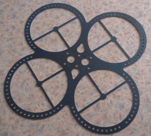
We did not even collect it. When I first took it in my hands, it became immediately clear that it was incredibly heavy. But after analyzing our mistakes, we highly optimized it and got this design:
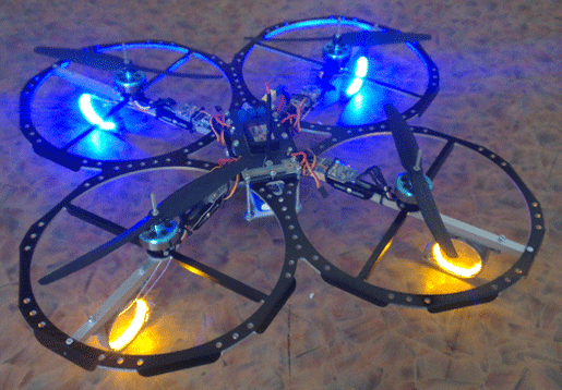
With this frame, the copter looked incredibly cool! And this frame had good vibration isolation. The copter consisted of two massive, vibration-proof parts - electronics with a battery and circles with engines ...
..., but it was still very heavy - more than 1.5 kg with a battery. Flight time was 3-4 minutes. Of course, he was already flying more stable, but he could not remain in this form and we started to work on the current version of the frame.
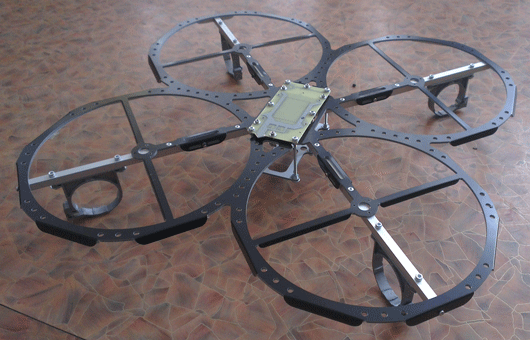
As a result, we abandoned the vibration isolation but carefully worked out a lot of other details.
First, we abandoned the power distributor board. Instead, we designed the frame so that it has a cavity in the middle in which all the wires are hidden. The wires for the backlight are also passed through the frame beams.
Secondly, we very accurately marked the seats for the flight controller and engines. NAZA must stand in the middle and with us it is ensured with precision CNC machine.
Thirdly, we have previously thought up landing pillars.
However, it is easier to see once.
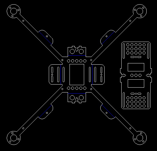
The drawing of the cutting frame is made in Nanocad. White lines - through cut, blue - V-shaped kerf along the lines of the bend. The whole frame consists of two parts - the cross and the platform for the battery. Her cutting cost about 800 rubles.
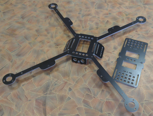
And here is the cut blank:
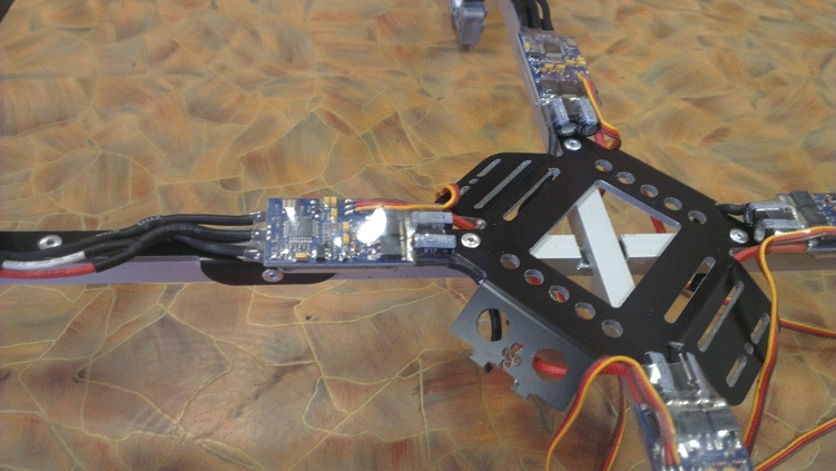
As guides, we used a 10x10 aluminum profile. Composite billet mounted on it with rivets. In this picture, the profile is not very well sealed. A little later, we will talk about how we redid the crosshair.
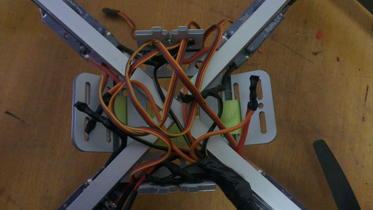
Next, we set the stroke controls and connected all the supply chains by soldering. Connections are made on the underside of the copter and are closed with a battery cover.
Then the ears are bent and screwed pad for the battery. We stuck silicone pads on this pad so that the battery does not slide. The battery itself is mounted on two Velcro.
We paid special attention to the supports. The first image shows that they are quite far apart. Due to this, even when the copter lands with a large roll, the rotating screws do not touch the ground. The supports themselves are made from holders of plumbing pipes. An LED tape - navigation lights are installed in the same rings. Please note that the wires from it also go into the bowels of the frame:

This solution has a flaw. When hard landings is a big load on the spider. At the very first flights the frame broke and we once again reassembled the kopter.
Now one beam of the copter is integral, and the second is interrupted and strengthened by an I-beam:
We are very pleased with the work done. The copter looks aesthetically pleasing and flies quite stably, even without GPS. If you want to assemble the same frame, here you can download the frame drawing in * .dwg format.
In conclusion, the section on the frame is one of its first flights, which took place at the exhibition timed to the International Programming Olympiad. The pilot is my younger brother.
My main article on frame experiences is on my blog .
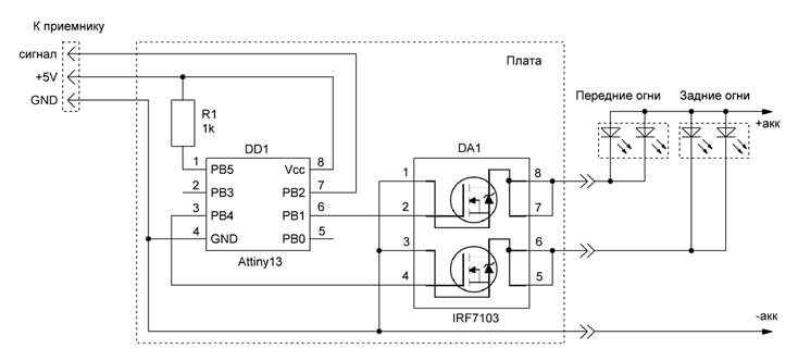
We also developed a very simple board that allows you to control the backlight of the copter from the console. The illumination of the copter is needed to determine the orientation of the copter in space and for decorative purposes.
The control board contains the minimum of possible elements: an Attiny13 microcontroller, a transistor assembly, a resistor, and two connectors. On the diagram, the module itself and the highlighting conventionally shown:
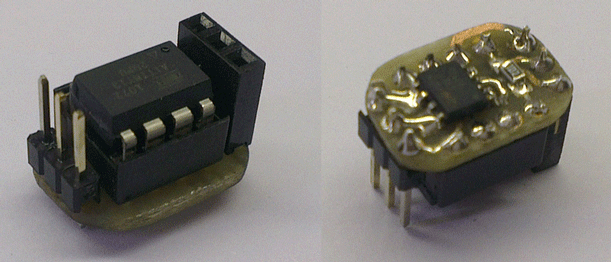
The board is powered and controlled via the receiver connector. If you install an angled connector on it, you can even plug it straight into the receiver. The dimensions are slightly larger than the DIP8 case. I took the chip in DIP to program it in a ZIF socket. And also to place other elements under it.

The microcontroller program implements four effects:
Video demo:
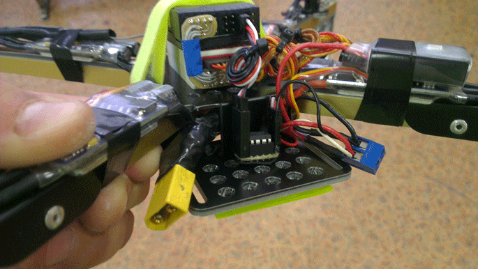
And this is how we installed this board on the frame:
Download links: board , hex . Fyuz bits need to leave the factory.
This is the repost part of the main article from my blog .
Among other things, all that we have mastered during the work on the copter, we posted in our blog. It turned out quite a complete series of articles. It may seem superficial, but for a beginner it will be enough for a very long time. Here are links to all parts of our series of articles:
Part 1. What is quadcopter
Part 2. Elements of quadrocopter
Part 3. All about quadcopter batteries
Part 4. Quadcopter frame
Part 5. Copter lights
Part 6. Connecting quadcopter elements
Part 7. Configuring Turnigy9x Remote for Copter
Part 8. Setting the speed controllers brushless motor
Part 9. Setting the flight controller DJI NAZA
Among other things, I enjoy climbing. There is a camera on our copter and I didn’t have a question “what to shoot”.
We made a short video of a rock climbing workout. Its quality is rather low - remember that this video was not made by professionals, a homemade copter on GoPro in Chinese:
Since the publication of this article, many times they have asked me to sell a backlight control board. In this regard, I decided to make several modules, so that you can buy a ready-made, assembled and programmed module.
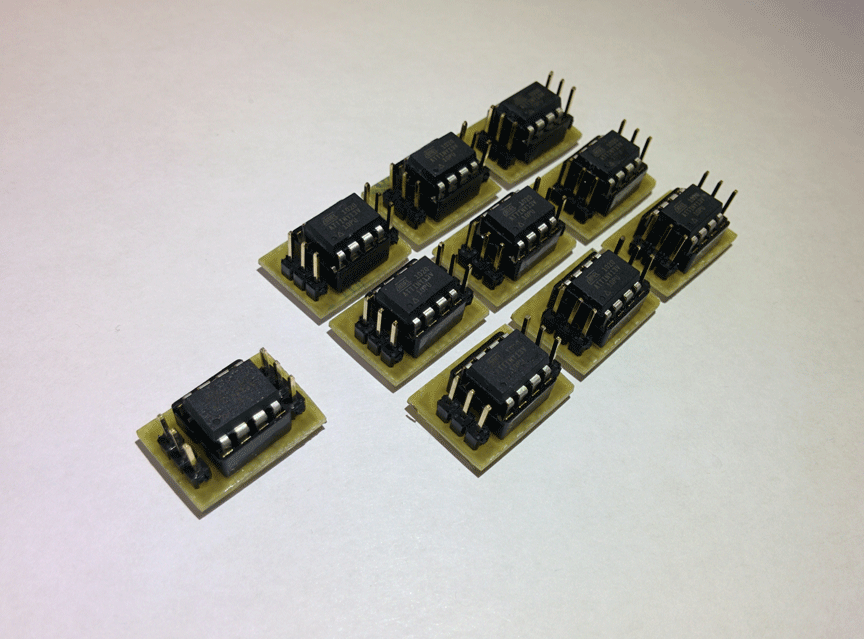
Specifically, these boards are programmed to flash as in the video:
Such regimes are more popular, as practice has shown. If you want something else, then email me this and I will do what you need.
If you want to purchase a ready-made fee, just email me at info@customelectronics.ru.
Now my copter looks like this:
I built my kopter in pair with my younger brother and I had the main goal to carry it away with electronics. I had no desire to develop mathematical algorithms from scratch. We just, like many, took ready-made elements and put everything together. We took the DJI NAZA flight controller with the Turnigy 9x radio control equipment as a basis. On our own, we developed only the frame and the navigation light control unit which we will talk about.
The first experiments with the frame
The simplest solution is to twist a cross from the aluminum profile. For the connection, we used a fee, which concurrently became a power distributor:
')
We even attached a little protection to the flight controller to it. With this frame we flew for the first time, but there was little pleasure. The screws constantly broke, it was all crooked and poorly thought out, and in the end the power supply on one of the regulators disappeared. As a result, we decided to make a brand new frame.
We decided to make a new frame from composite material. To begin with, we did the first thing that came to mind and cut out this:
We did not even collect it. When I first took it in my hands, it became immediately clear that it was incredibly heavy. But after analyzing our mistakes, we highly optimized it and got this design:
With this frame, the copter looked incredibly cool! And this frame had good vibration isolation. The copter consisted of two massive, vibration-proof parts - electronics with a battery and circles with engines ...
..., but it was still very heavy - more than 1.5 kg with a battery. Flight time was 3-4 minutes. Of course, he was already flying more stable, but he could not remain in this form and we started to work on the current version of the frame.
The final frame
As a result, we abandoned the vibration isolation but carefully worked out a lot of other details.
First, we abandoned the power distributor board. Instead, we designed the frame so that it has a cavity in the middle in which all the wires are hidden. The wires for the backlight are also passed through the frame beams.
Secondly, we very accurately marked the seats for the flight controller and engines. NAZA must stand in the middle and with us it is ensured with precision CNC machine.
Thirdly, we have previously thought up landing pillars.
However, it is easier to see once.
The drawing of the cutting frame is made in Nanocad. White lines - through cut, blue - V-shaped kerf along the lines of the bend. The whole frame consists of two parts - the cross and the platform for the battery. Her cutting cost about 800 rubles.
And here is the cut blank:
As guides, we used a 10x10 aluminum profile. Composite billet mounted on it with rivets. In this picture, the profile is not very well sealed. A little later, we will talk about how we redid the crosshair.
Next, we set the stroke controls and connected all the supply chains by soldering. Connections are made on the underside of the copter and are closed with a battery cover.
Then the ears are bent and screwed pad for the battery. We stuck silicone pads on this pad so that the battery does not slide. The battery itself is mounted on two Velcro.
We paid special attention to the supports. The first image shows that they are quite far apart. Due to this, even when the copter lands with a large roll, the rotating screws do not touch the ground. The supports themselves are made from holders of plumbing pipes. An LED tape - navigation lights are installed in the same rings. Please note that the wires from it also go into the bowels of the frame:
This solution has a flaw. When hard landings is a big load on the spider. At the very first flights the frame broke and we once again reassembled the kopter.
Now one beam of the copter is integral, and the second is interrupted and strengthened by an I-beam:
We are very pleased with the work done. The copter looks aesthetically pleasing and flies quite stably, even without GPS. If you want to assemble the same frame, here you can download the frame drawing in * .dwg format.
In conclusion, the section on the frame is one of its first flights, which took place at the exhibition timed to the International Programming Olympiad. The pilot is my younger brother.
My main article on frame experiences is on my blog .
Copter backlight
We also developed a very simple board that allows you to control the backlight of the copter from the console. The illumination of the copter is needed to determine the orientation of the copter in space and for decorative purposes.
The control board contains the minimum of possible elements: an Attiny13 microcontroller, a transistor assembly, a resistor, and two connectors. On the diagram, the module itself and the highlighting conventionally shown:
The board is powered and controlled via the receiver connector. If you install an angled connector on it, you can even plug it straight into the receiver. The dimensions are slightly larger than the DIP8 case. I took the chip in DIP to program it in a ZIF socket. And also to place other elements under it.
The microcontroller program implements four effects:
- Continuous glow
- Single flash
- Dual flashes
- Alternate inclusion
Video demo:
And this is how we installed this board on the frame:
Download links: board , hex . Fyuz bits need to leave the factory.
This is the repost part of the main article from my blog .
Conclusion
Among other things, all that we have mastered during the work on the copter, we posted in our blog. It turned out quite a complete series of articles. It may seem superficial, but for a beginner it will be enough for a very long time. Here are links to all parts of our series of articles:
Part 1. What is quadcopter
Part 2. Elements of quadrocopter
Part 3. All about quadcopter batteries
Part 4. Quadcopter frame
Part 5. Copter lights
Part 6. Connecting quadcopter elements
Part 7. Configuring Turnigy9x Remote for Copter
Part 8. Setting the speed controllers brushless motor
Part 9. Setting the flight controller DJI NAZA
PS:
Among other things, I enjoy climbing. There is a camera on our copter and I didn’t have a question “what to shoot”.
We made a short video of a rock climbing workout. Its quality is rather low - remember that this video was not made by professionals, a homemade copter on GoPro in Chinese:
UPD
Since the publication of this article, many times they have asked me to sell a backlight control board. In this regard, I decided to make several modules, so that you can buy a ready-made, assembled and programmed module.
Specifically, these boards are programmed to flash as in the video:
Such regimes are more popular, as practice has shown. If you want something else, then email me this and I will do what you need.
If you want to purchase a ready-made fee, just email me at info@customelectronics.ru.
Source: https://habr.com/ru/post/236091/
All Articles