Button gouging and pedaling Vim
About the button gouging, I first heard the year in 2005. The essence of the device was that pressing the button hidden under the carpet led to the minimization of all the windows on the monitor, so that the chef suddenly appeared not to see what you are really doing at work. Then it was positioned as a fashionable gadget for progressive youth.
So it would have been in the depths of memory if not for the article “Pedaling Vim” . And then just on the table lay some hardware keys on the AT90USB162, which we are releasing to protect our software.

And I decided to create my own version of the universal pedal. Yes, such that it was possible to send any combination of both pressing and releasing the pedal. In terms of the number, I decided to limit myself to three combinations, one after the other, and three more to release.
')
So, our keys did not have any additional pads. The exception is the Reset and HWB buttons, which are necessary to run a regular bootloader for USB firmware. Yes, yes, the programmer is not needed, only the Atmel Flip program is needed . All chips from the factory are stitched with a regular bootloader.
Reset does not use, but the HWB in normal mode - just the port PD7 and it can be used at will. In fairness, I note that there are no restrictions on the number of pedals. In the case of reworking the board or buying a finished board in China , the number of pedals can be increased to two dozen (the “Chinese” has 21 pad).
In the text above, by the way, the answer to 3 questions of future comments:
1. Why on AVR?
2. Why not arduin?
3. Why only one button?
So, the Atmel example of the HID keyboard on the AT90USB MK series *** was taken as the basis. It is described in detail in the apn " AVR271: USB Keyboard Demonstration " ( here translation ) and I will not dwell on it. This example can be compiled under both GCC and IAR, I used IAR, version 6.3.3.1990.
Interrupt pedals are not used to handle pressing - practice has shown that a simple polling speed is more than enough even with anti-debugging delays. All useful work — polling and sending a request — takes place in the keyboard_task.c file. Kbd_test_hit () function; checks the pressing of a single button (pedal) HWB (PD7) for pressing or releasing, keyboard_task (void) sends the generated request to the PC. And what exactly to send, keyboard_task learns from eeprom.
We care about our customers, so we made it so that changing / adding combinations was as convenient as possible and did not force the user to install IAR and reassemble the code. The user just needs to manually fix the eeprom hex file! eight)
In the archive attached to the article there are three eeprom files with Win + D, Alt + Tab and i / Esc combinations for Vim (for the latter I am not sure, I did not check it in hardware). But if this is not enough, then open the file in notepad. We see the following:
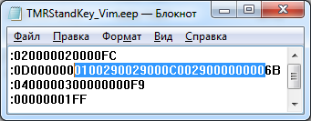
Dedicated 13 bytes, this is our package. Their structure is as follows:
The first byte determines whether we will respond only to pressing (0x00) or also to releasing (0x01) the pedals. Next come 3 pairs of bytes of a send to press and 3 pairs of bytes of a send to release. A couple of bytes, this is a byte of modifiers and a byte of the button code itself. In the modifier byte, each bit corresponds to pressing a single modifier button (Ctrl, Alt, Win etc.). If we want to transmit several modifiers at once (for example, Ctrl + Shift), we set several bits in the byte corresponding to these modifiers. All key and modifier codes are present in the usb_commun_hid.h file. or they can be found in the internet .
The MK program plays the recording from the eeprom like a tape recorder to the USB port, so what is inserted there will be sent by the OS without correction. Bytes that are not needed are replaced with zeros - the code 0x00 means “no_key” and the OS does not accept it. Later, I thought that the first byte, which determines the response to pressing, is, in general, not needed, it is enough to score unnecessary pairs of bytes with zeros, but something was too lazy to change. I will do on condition of worldwide success of the design.
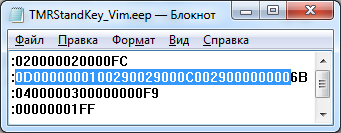
So, you have made the necessary adjustments to the file. Now you need to calculate the checksum of the string. To do this, copy the string from the colon to the last byte (not including them), as shown in the picture below, and consider the COP, for example, here or by hand. The result is entered into the last byte of the line of the eeprom file. Persist. We sew.
Instructions for flip flashing in the network of the sea , everything is standard. There is only one subtlety - in order to flash an eeprom, you must flash the flash first, otherwise there is no way. In the attached archive there are two flash firmware - for boards with quartz 8 and 16 MHz. I recommend using 16 MHz, especially if you are going to make a lot of buttons. Please note that the Chinese on their boards reflash the chips with their bootmaker Teensy Loader (these boards only have a Reset button, they don’t use HWB) and Flip doesn’t work with it, they have their own firmware for firmware, but the procedure is generally the same.
The archive below the article contains: the source of the project, ready * .hex & * .eep firmware files, drawing of the board in SprintLayout5 format and gerber files in the oshpark campaign format , as well as a high-resolution circuit and various photos.
And of course, demonstrating.
Where to use this product? In fact, many where. For example, in flight simulators, by matching the toggle switches on the panel of a virtual airplane on def. keyboard keys, you can build your own dashboard with iron toggle switches. In games. In keyboards for people with disabilities, etc.
PS Apparently, I still do not deserve to invest, so: yadi.sk
So it would have been in the depths of memory if not for the article “Pedaling Vim” . And then just on the table lay some hardware keys on the AT90USB162, which we are releasing to protect our software.
And I decided to create my own version of the universal pedal. Yes, such that it was possible to send any combination of both pressing and releasing the pedal. In terms of the number, I decided to limit myself to three combinations, one after the other, and three more to release.
')
So, our keys did not have any additional pads. The exception is the Reset and HWB buttons, which are necessary to run a regular bootloader for USB firmware. Yes, yes, the programmer is not needed, only the Atmel Flip program is needed . All chips from the factory are stitched with a regular bootloader.
Reset does not use, but the HWB in normal mode - just the port PD7 and it can be used at will. In fairness, I note that there are no restrictions on the number of pedals. In the case of reworking the board or buying a finished board in China , the number of pedals can be increased to two dozen (the “Chinese” has 21 pad).
In the text above, by the way, the answer to 3 questions of future comments:
1. Why on AVR?
2. Why not arduin?
3. Why only one button?
So, the Atmel example of the HID keyboard on the AT90USB MK series *** was taken as the basis. It is described in detail in the apn " AVR271: USB Keyboard Demonstration " ( here translation ) and I will not dwell on it. This example can be compiled under both GCC and IAR, I used IAR, version 6.3.3.1990.
Interrupt pedals are not used to handle pressing - practice has shown that a simple polling speed is more than enough even with anti-debugging delays. All useful work — polling and sending a request — takes place in the keyboard_task.c file. Kbd_test_hit () function; checks the pressing of a single button (pedal) HWB (PD7) for pressing or releasing, keyboard_task (void) sends the generated request to the PC. And what exactly to send, keyboard_task learns from eeprom.
We care about our customers, so we made it so that changing / adding combinations was as convenient as possible and did not force the user to install IAR and reassemble the code. The user just needs to manually fix the eeprom hex file! eight)
In the archive attached to the article there are three eeprom files with Win + D, Alt + Tab and i / Esc combinations for Vim (for the latter I am not sure, I did not check it in hardware). But if this is not enough, then open the file in notepad. We see the following:
Dedicated 13 bytes, this is our package. Their structure is as follows:
The first byte determines whether we will respond only to pressing (0x00) or also to releasing (0x01) the pedals. Next come 3 pairs of bytes of a send to press and 3 pairs of bytes of a send to release. A couple of bytes, this is a byte of modifiers and a byte of the button code itself. In the modifier byte, each bit corresponds to pressing a single modifier button (Ctrl, Alt, Win etc.). If we want to transmit several modifiers at once (for example, Ctrl + Shift), we set several bits in the byte corresponding to these modifiers. All key and modifier codes are present in the usb_commun_hid.h file. or they can be found in the internet .
The MK program plays the recording from the eeprom like a tape recorder to the USB port, so what is inserted there will be sent by the OS without correction. Bytes that are not needed are replaced with zeros - the code 0x00 means “no_key” and the OS does not accept it. Later, I thought that the first byte, which determines the response to pressing, is, in general, not needed, it is enough to score unnecessary pairs of bytes with zeros, but something was too lazy to change. I will do on condition of worldwide success of the design.
So, you have made the necessary adjustments to the file. Now you need to calculate the checksum of the string. To do this, copy the string from the colon to the last byte (not including them), as shown in the picture below, and consider the COP, for example, here or by hand. The result is entered into the last byte of the line of the eeprom file. Persist. We sew.
Instructions for flip flashing in the network of the sea , everything is standard. There is only one subtlety - in order to flash an eeprom, you must flash the flash first, otherwise there is no way. In the attached archive there are two flash firmware - for boards with quartz 8 and 16 MHz. I recommend using 16 MHz, especially if you are going to make a lot of buttons. Please note that the Chinese on their boards reflash the chips with their bootmaker Teensy Loader (these boards only have a Reset button, they don’t use HWB) and Flip doesn’t work with it, they have their own firmware for firmware, but the procedure is generally the same.
The archive below the article contains: the source of the project, ready * .hex & * .eep firmware files, drawing of the board in SprintLayout5 format and gerber files in the oshpark campaign format , as well as a high-resolution circuit and various photos.
And of course, demonstrating.
Where to use this product? In fact, many where. For example, in flight simulators, by matching the toggle switches on the panel of a virtual airplane on def. keyboard keys, you can build your own dashboard with iron toggle switches. In games. In keyboards for people with disabilities, etc.
PS Apparently, I still do not deserve to invest, so: yadi.sk
Source: https://habr.com/ru/post/235711/
All Articles