Another "smart" outlet with your own hands. Part 1
Yes Yes Yes. Another one. I understand, everyone is tired. But I really wanted to make myself, my own "smart" outlet, with lotto and female students. Embedded (in the house - hidden wiring). Managed via WiFi (locally) and the Internet (globally). With the receipt of the current status (in the future - with information about consumption). With the connection of several outlets in one unit (up to four). With temperature, light and presence sensors. With a video camera, after all!
The first part - just check the overall performance of the circuit. In fact, it is a kind of analogue of the WeMo Switch , only embedded in a standard podrozetnik and therefore not tied to any particular design (to fit into any already existing interior).
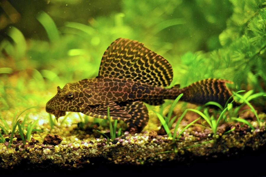
So, what do you want? I want to manage each of the four sockets independently (in my house in one of the rooms the sockets are combined into blocks of two two-socket modules close to each other, in two standard plastic boxes, respectively). All units (lighting, filter pump, heater, compressor) of an aquarium with a beautiful brocade catfish are connected to one of these units, and we will manage them. Somik here such, if that (picture to attract attention):
')
So what do we want?
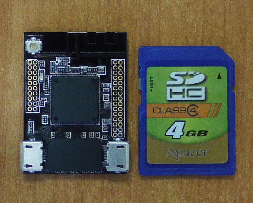
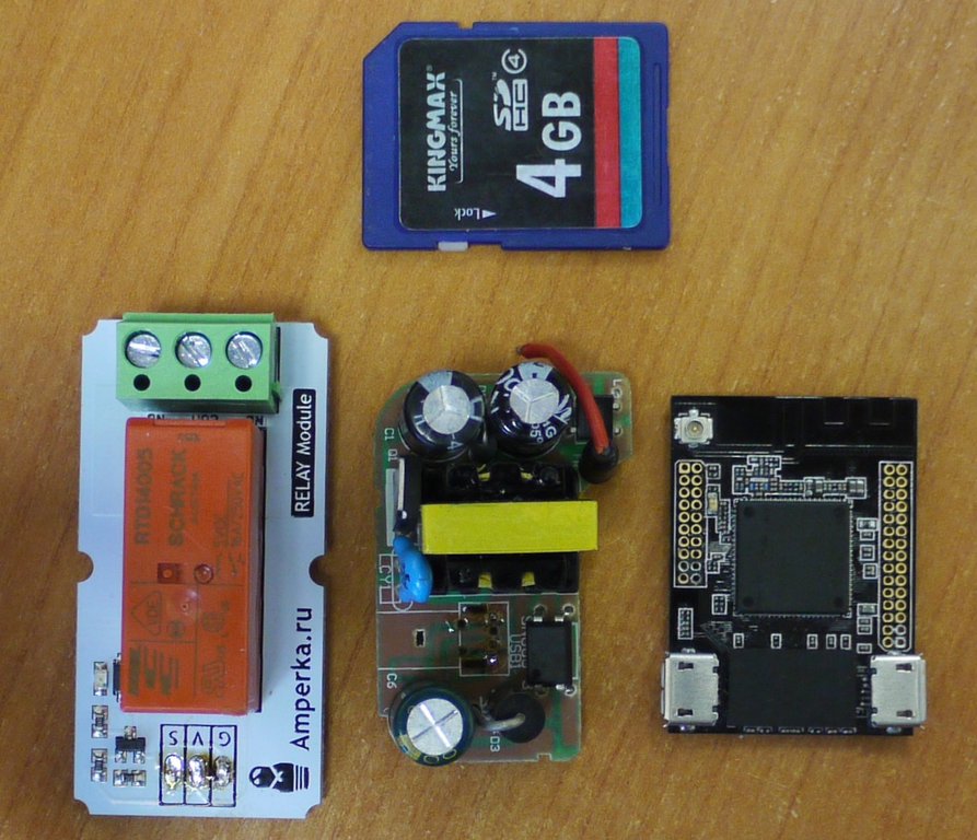
1. Receive commands via WiFi and issue the appropriate control signals to close the contacts. Those. I need a controller module with WiFi. Since I have our kerchief on the AR9331 (a piano in the bushes, yes: actually, I wanted to try it out in the beginning), it will be such a controller.
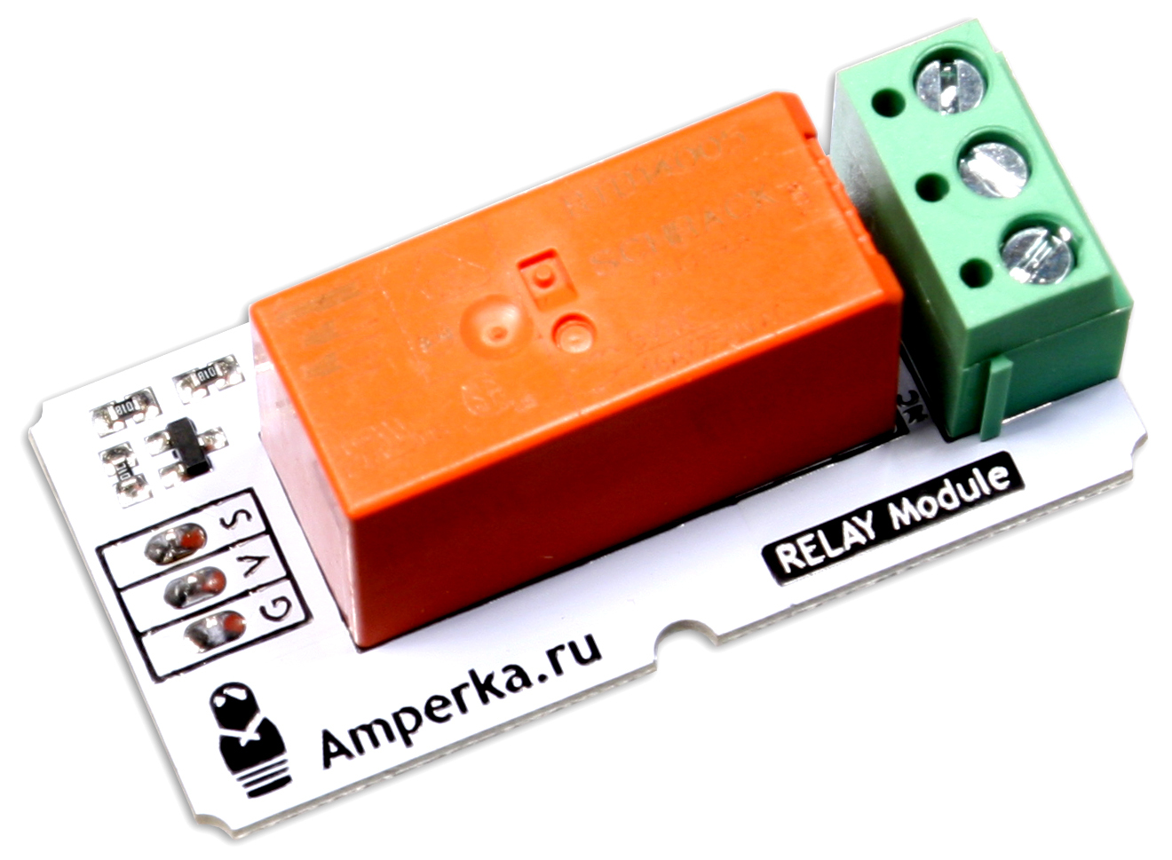
2. Relay for 16A 220V. In order not to bother - I took the finished module from Amperki . At the same time there is a LED to indicate the mode of operation of the outlet.
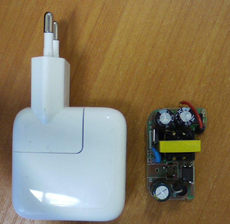
3. To power these two modules with a voltage of 5V. Disassembled compact power supply with USB connector.
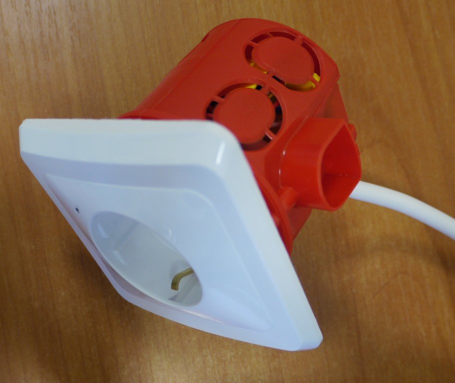
4. Podrozetnik depth of 60mm.

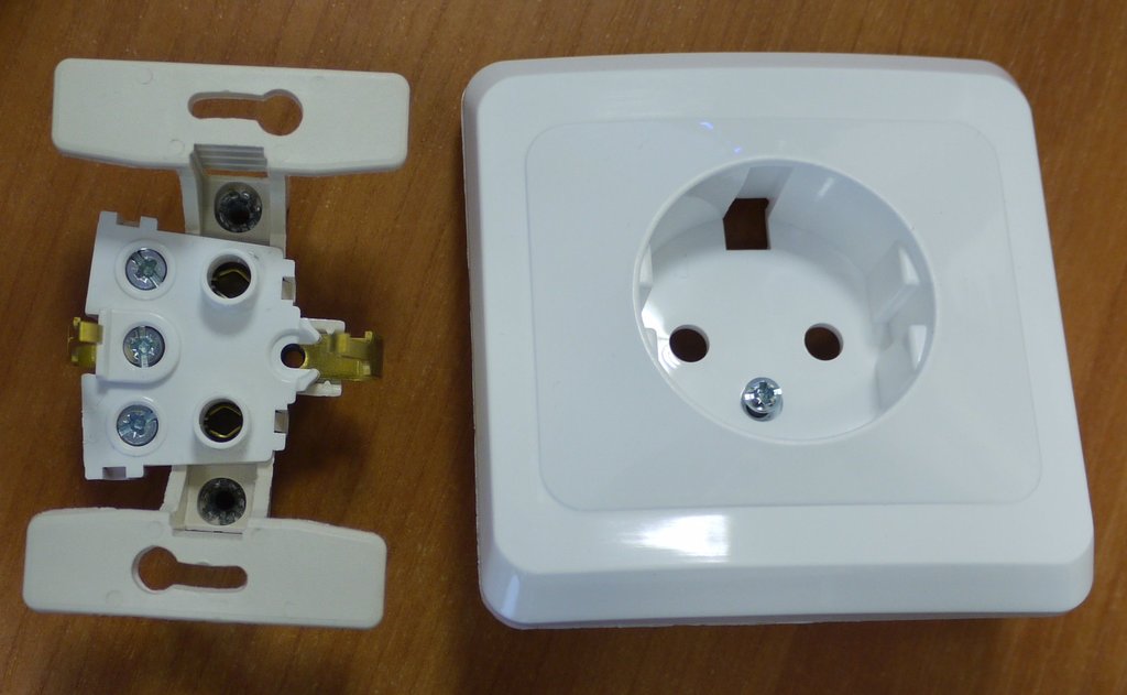
5. Actually the outlet (so far for the experiments I took the first one that came to the next hardware store):
6. LED to indicate the mode of operation of the outlet (On / Off). I found in my bedside table green and red. At first I wanted to use green (I like the color more), but it was not bright enough, so as a result I took red.
I figured the scheme (primitive, yes):

Spread out the components:
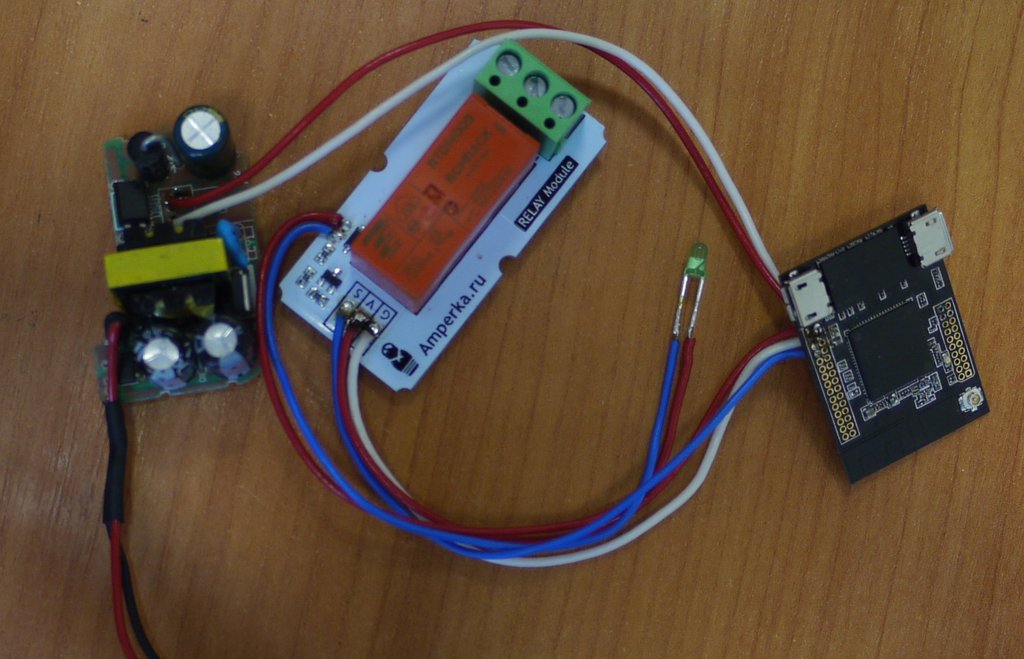
Cut wires, soldered:
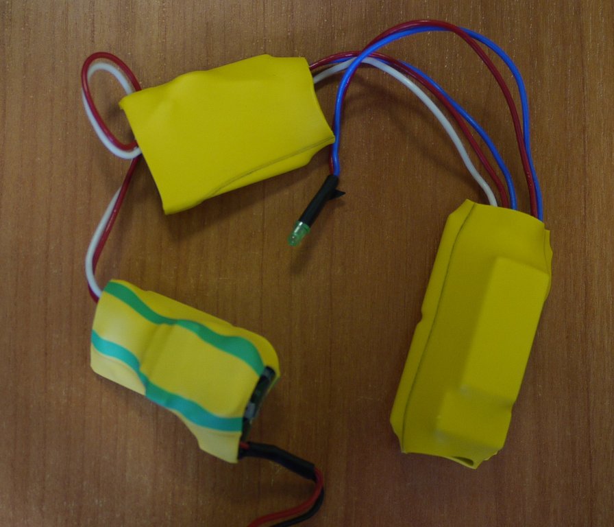
Cut pieces of heat shrink tubing, insulated modules:
I shoved everything into a plug, connected the cable, plugged it into an outlet. While it is still too early to shove the wall, you need to debug on the table.
In order for the LED to be seen better, I made a small hole in the socket with a thin soldering iron tip.
The test bench is ready.
The software for the initial simple check took from the post uv. Ariman'a.
Well ... Surprisingly, but it works. The relay clicks, the LED blinks, electricity is supplied to the outlet. The first step has been taken. It took about an hour and a half in total. Of money:
1. Controller on AR9331 - I don’t even know how to evaluate. Let it be 750r - at this price we are going to sell it when we make a batch.
2. Relay module - 290r.
3. Power supply - well, let it be 200r (I saw it in the underground passage at that price, mine, I’ve been lying around for a couple of years).
4. Podrozetnik - 45r.
5. Socket - 120r.
Total: 1405r.
Now we need to bring to mind the software (first of all - the firmware). About this - in the next part, if people will be interested. And then I will connect the sensors and three more relay modules to control four sockets, not just one.
PS Connected a video camera - it works, where does it go? But it is necessary to enter it somehow into the interior, I have not yet invented - how ... And in terms of software - it is necessary to learn how to stream the Internet to broadcast, and not just to LAN.
The first part - just check the overall performance of the circuit. In fact, it is a kind of analogue of the WeMo Switch , only embedded in a standard podrozetnik and therefore not tied to any particular design (to fit into any already existing interior).
So, what do you want? I want to manage each of the four sockets independently (in my house in one of the rooms the sockets are combined into blocks of two two-socket modules close to each other, in two standard plastic boxes, respectively). All units (lighting, filter pump, heater, compressor) of an aquarium with a beautiful brocade catfish are connected to one of these units, and we will manage them. Somik here such, if that (picture to attract attention):
')
So what do we want?
1. Receive commands via WiFi and issue the appropriate control signals to close the contacts. Those. I need a controller module with WiFi. Since I have our kerchief on the AR9331 (a piano in the bushes, yes: actually, I wanted to try it out in the beginning), it will be such a controller.
2. Relay for 16A 220V. In order not to bother - I took the finished module from Amperki . At the same time there is a LED to indicate the mode of operation of the outlet.
3. To power these two modules with a voltage of 5V. Disassembled compact power supply with USB connector.
4. Podrozetnik depth of 60mm.
5. Actually the outlet (so far for the experiments I took the first one that came to the next hardware store):
6. LED to indicate the mode of operation of the outlet (On / Off). I found in my bedside table green and red. At first I wanted to use green (I like the color more), but it was not bright enough, so as a result I took red.
I figured the scheme (primitive, yes):
Spread out the components:
Cut wires, soldered:
Cut pieces of heat shrink tubing, insulated modules:
I shoved everything into a plug, connected the cable, plugged it into an outlet. While it is still too early to shove the wall, you need to debug on the table.
In order for the LED to be seen better, I made a small hole in the socket with a thin soldering iron tip.
The test bench is ready.
The software for the initial simple check took from the post uv. Ariman'a.
Well ... Surprisingly, but it works. The relay clicks, the LED blinks, electricity is supplied to the outlet. The first step has been taken. It took about an hour and a half in total. Of money:
1. Controller on AR9331 - I don’t even know how to evaluate. Let it be 750r - at this price we are going to sell it when we make a batch.
2. Relay module - 290r.
3. Power supply - well, let it be 200r (I saw it in the underground passage at that price, mine, I’ve been lying around for a couple of years).
4. Podrozetnik - 45r.
5. Socket - 120r.
Total: 1405r.
Now we need to bring to mind the software (first of all - the firmware). About this - in the next part, if people will be interested. And then I will connect the sensors and three more relay modules to control four sockets, not just one.
PS Connected a video camera - it works, where does it go? But it is necessary to enter it somehow into the interior, I have not yet invented - how ... And in terms of software - it is necessary to learn how to stream the Internet to broadcast, and not just to LAN.
Source: https://habr.com/ru/post/235479/
All Articles