How to cross the designer "Expert" and Arduino do it yourself
I will not tell you what it is and how to write sketches.
I will not explain how the end should hold a soldering iron.
I will not argue the pros and cons of the existence of an electronic designer on the clothing buttons.
I will tell you the story of the successful experience of crossing the constructor "Expert" and Arduino in a single household.
One evening, we are going to assemble a scheme from the “Expert” constructor with the child. Turn on. I smell burning plastic. Turn off. I analyze the circuit and see that in my edition of the circuit of the respected AA Bakhmetyev, the transistor unsuccessfully modulates the chemical source of voltage, giving out its sincere perturbation of temperature.
')
The transistor is dead as a result. And I replaced it again:

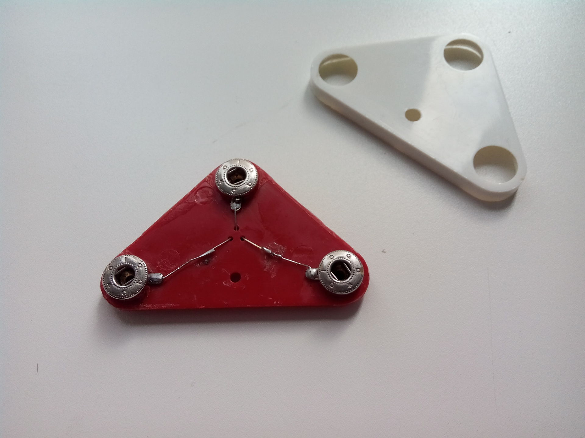
To do this, it was necessary to break off the white bottom cover, but valuable experience was gained in analyzing the details of the designer:
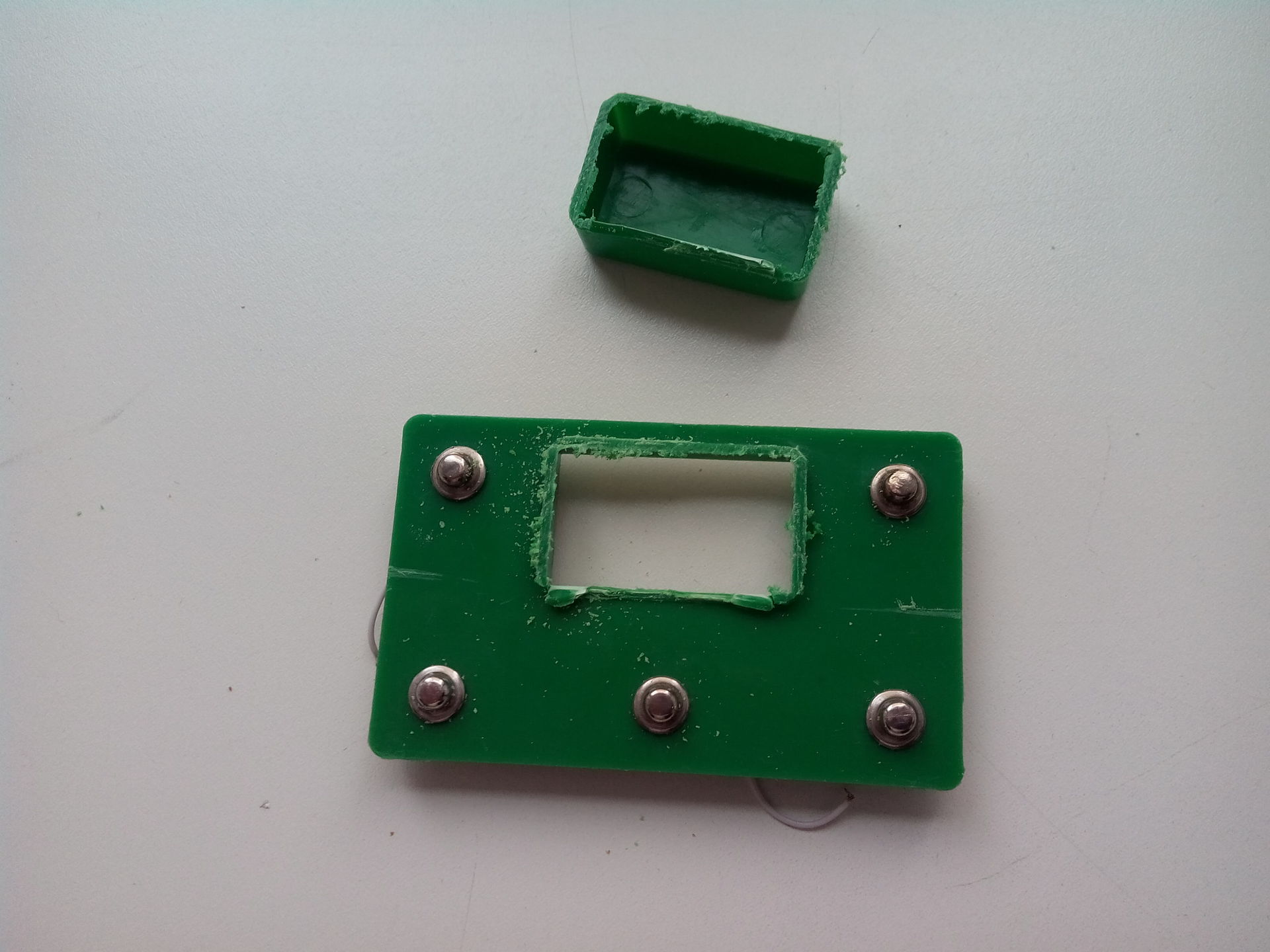
The young experimenter did not stop on his laurels and soon said: “Houston, we have a problem: failure of block 23”:
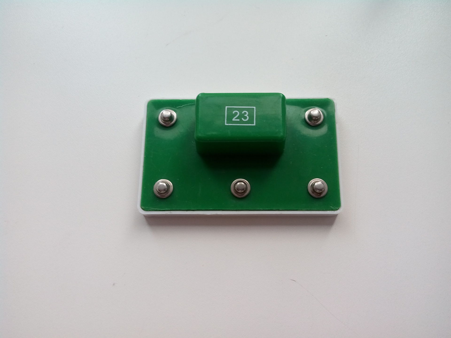
This is where the experience of parsing a block with a transistor was useful. Inside the block 23 are two drop-shaped chips with the marking TAIKONG-1 and TAIKONG-2, as well as the transistor S9012. I replaced the transistor, although it was serviceable, but the unit did not come to life. Since I did not have an electron microscope, I had to google a lot. Apparently, this module was supposed to make the sounds of “Piu-Piu-Piu” and “Tysch-Tysch-Tysch”, depending on which leg is on the ground. If both legs were on the ground, the combination “Piu-Tysch-Piu-Tysch” sounded.
The next evening the block 21 died. Inside the block there are two transistors (already familiar S8050 and S9012). Replacement does not lead to anything. The marking on the CLZSD1 board did not give way to Google. Interestingly, the melody is only one protection, but you can set its duration through the resistance between the legs.
As time went. Block 22 is dead. Inside the S8050 transistor and a microcircuit a droplet. CL9561 marking on the board. Replacing the transistor unit is not revived. Googling has shown that this board is widely used in children's toys (automatons, typewriters) and in children's alarm systems. Able to make sounds of fire and police sirens, ambulance and automatic fire, again, depending on what leg will be on the ground. That's right: two legs - four audio tracks.
The analog chips in the DIP and MSOP LM4871 package, or the KD9561 boards cost from $ 0.30 in a commercial batch or from $ 3 from 5pcs. I didn’t want to pay $ 15 for sound effects, especially in the evening of a difficult day when I wanted so much silence, and I safely forgot to forget.
Summary: repairing blocks is inappropriate:
I am not an arduinschik, but the idea of crossing the Arduino and the Designer Connoisseur was in the air. If the child has mastered the designer, let him continue to play in Arduino, especially since there is a Scratch for Arduino . Moving from the pitch of the legs 2.8cm to 2.5mm and for an adult is difficult, and even more so for a child. Therefore, it was decided: use the standard did "Expert". Go to the store for the clothing buttons and get the rates $ 1 per button. I did not expect this. For $ 20 you can buy "connoisseur" entry level.
Once, the Arduino Pro Mini 5V was turning in its hands. Sizes suitable. The power supply is suitable for the “Connoisseur” (4.8..6V = four batteries / rechargeable batteries). The price is adequate around $ 3. Sketches I do not trust the child yet. Here are just too many inputs / outputs, and the figure / analog selection adds degrees of freedom. How to dissolve all this into three legs of a standard block (two for power and ground)?
Take the block. Carefully disassemble. First, gently knock the block around the perimeter of the hammer, in the hope that the fragile glue will crack. Next, we drive a thin knife (and better a scalpel) between the block and the lid. Carefully shake and weaken the glue around the perimeter. After a couple of minutes of neat manipulations, the white protective cover is removed and we can see the inside of the unit.

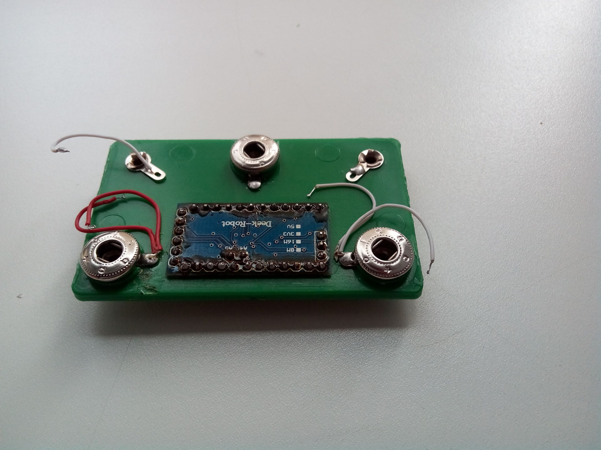
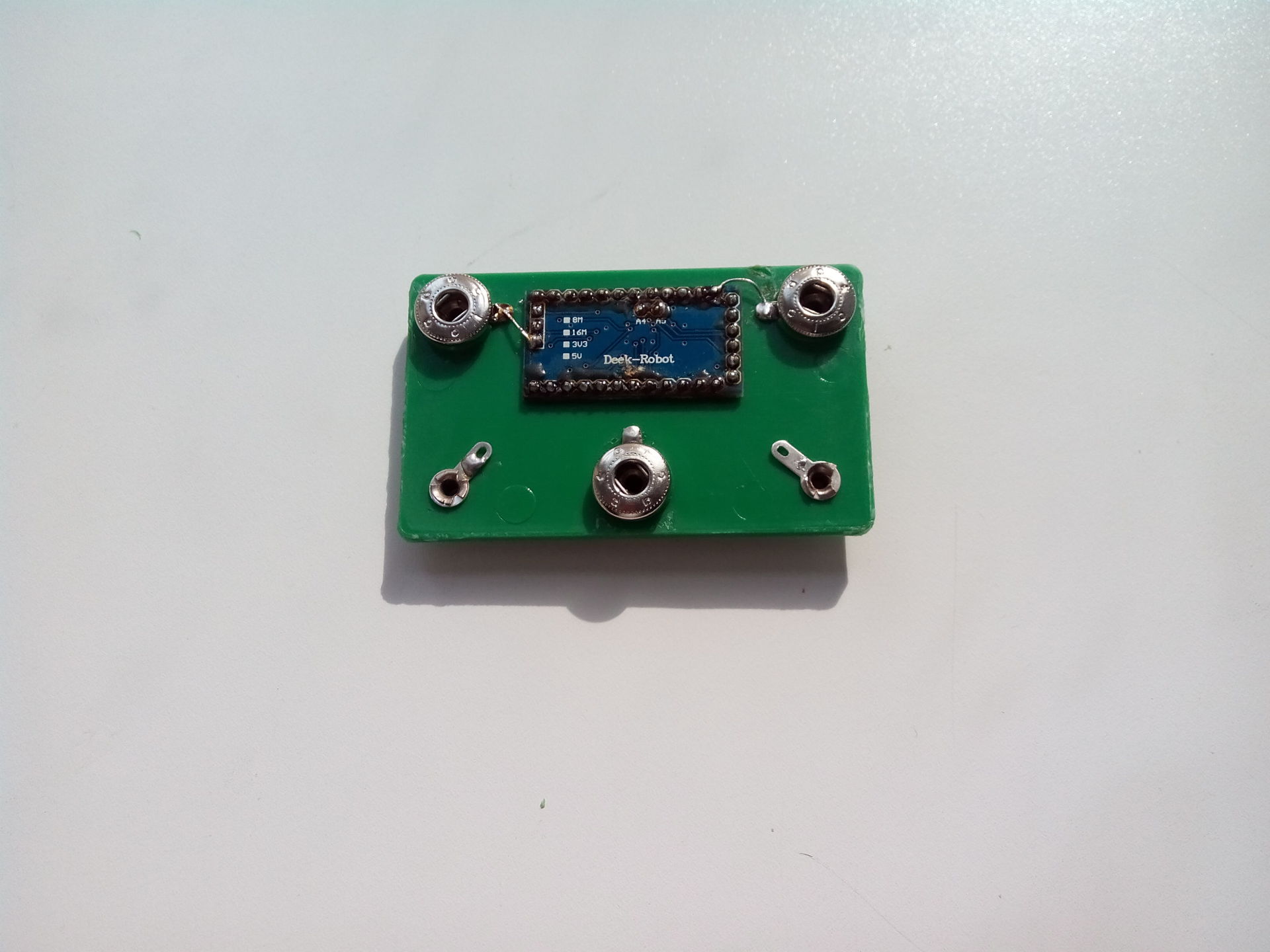
Ruthlessly pay off the board. It is unlikely that we still need it.
Cut down the block cover hacksaw or Dremel.

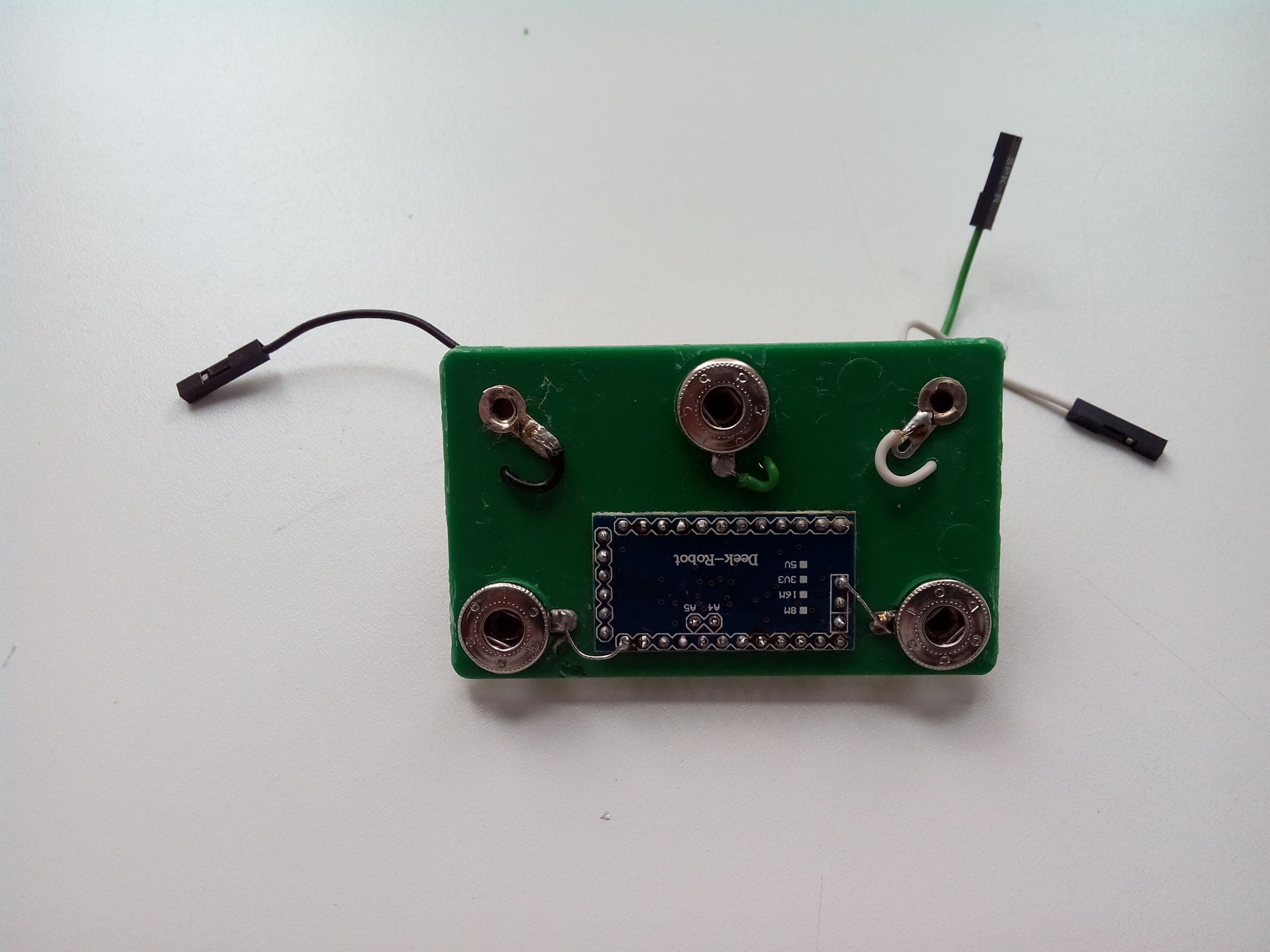
Slightly (literally by a millimeter) we increase the opening along the length. The Arduino Pro Mini should not slip through the hole. Seals pins. I was too lazy to think, so I soldered all the pins. Having a debugged sketch, you can solder only the necessary, or do without pins altogether. Pins with a skirt should penetrate into the hole (what else is called this black plastic ruler, which unites pins?)
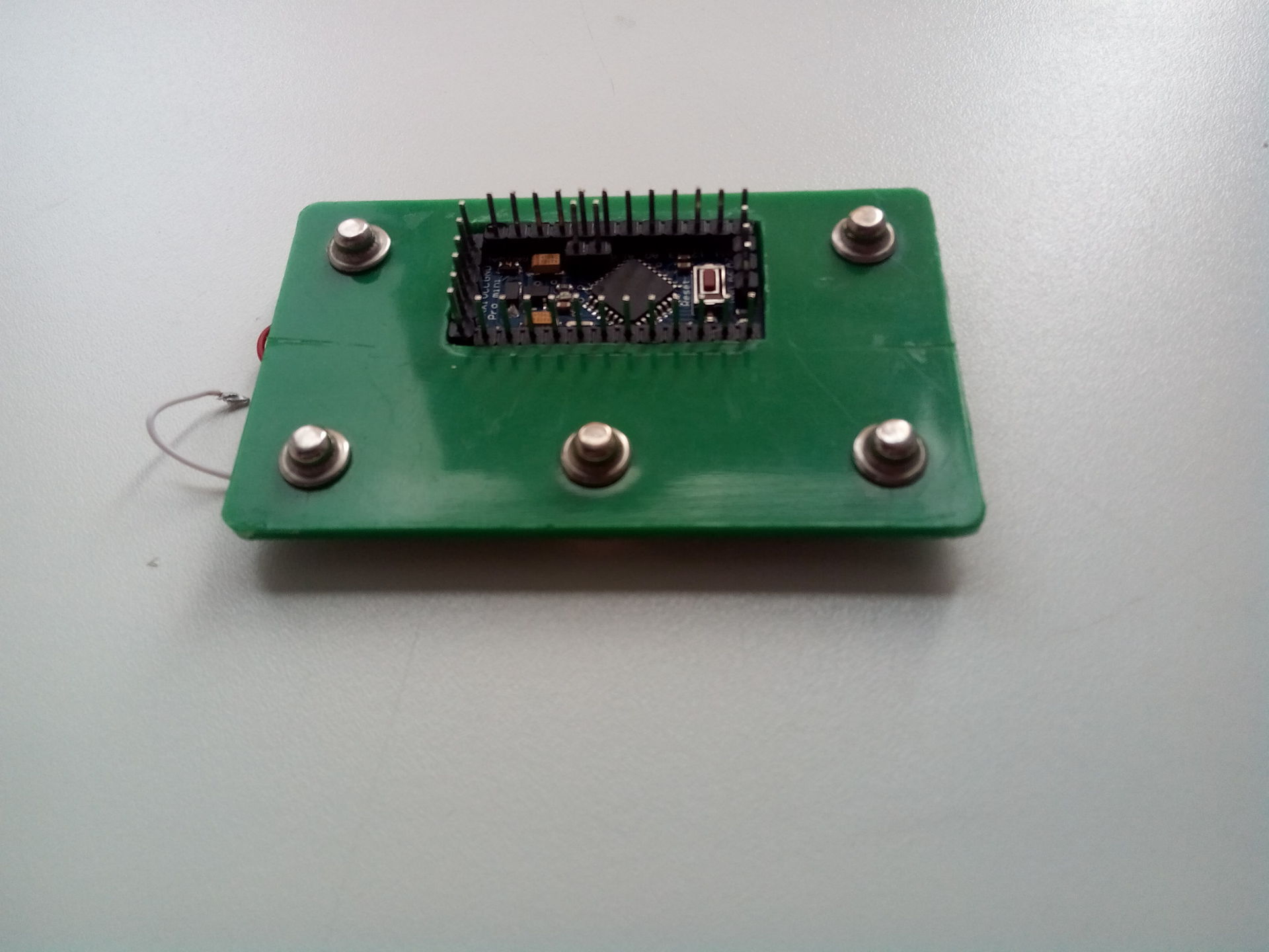
Seal food. Based on the standard for Connoisseur scheme: the top will be "+" (RAW), and the bottom will be "-" (GND).
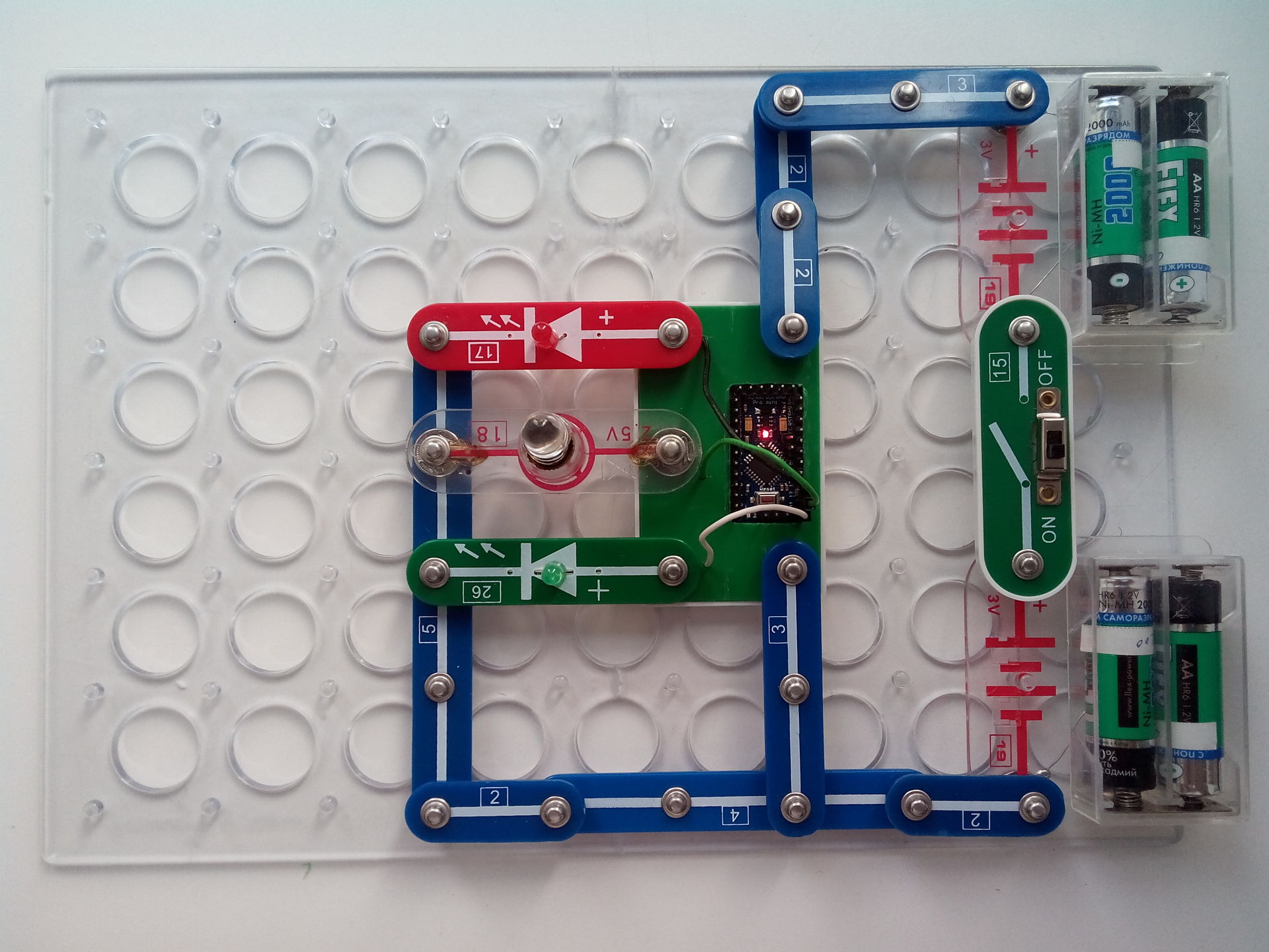
I could not resist - I collected the first scheme. Traditionally flashed built-in LED.
We launder the board and drill holes for the wires. We mean that the installed parts of the designer can block the holes and interfere with our wires, so it is better to retreat an additional 2..3 mm from the center of the button.
Fill the sketch of the traffic light. We collect the new scheme. We cling the wiring from the buttons to the appropriate legs. The Connoisseur kit contains only two LEDs, so I soldered the white-moon LED (there was no other at hand) into the base of the faulty light bulb. And enjoy!
The unit can be stored in a standard designer box, you just need to pull the wires out of the pins. (Or down pins, then you can not pull the wires).

It would be good to put the protection, Ohmov 20 on each of the three legs of the block, and provide a resurfacing. But the price of replacing the Arduino $ 3 is much lower than the bar of my laziness.
The new block of the designer "Expert" reanimated the child's interest in electronics. How now to name the new unit?
The support pin of the plastic base of the circuit board rests against the Arduino. Therefore, the board should be mounted on top of the unit, and not on the bottom, as described earlier. This option went into production:
To be continued
I will not explain how the end should hold a soldering iron.
I will not argue the pros and cons of the existence of an electronic designer on the clothing buttons.
I will tell you the story of the successful experience of crossing the constructor "Expert" and Arduino in a single household.
Prehistory
One evening, we are going to assemble a scheme from the “Expert” constructor with the child. Turn on. I smell burning plastic. Turn off. I analyze the circuit and see that in my edition of the circuit of the respected AA Bakhmetyev, the transistor unsuccessfully modulates the chemical source of voltage, giving out its sincere perturbation of temperature.
')
The transistor is dead as a result. And I replaced it again:
To do this, it was necessary to break off the white bottom cover, but valuable experience was gained in analyzing the details of the designer:
The young experimenter did not stop on his laurels and soon said: “Houston, we have a problem: failure of block 23”:
This is where the experience of parsing a block with a transistor was useful. Inside the block 23 are two drop-shaped chips with the marking TAIKONG-1 and TAIKONG-2, as well as the transistor S9012. I replaced the transistor, although it was serviceable, but the unit did not come to life. Since I did not have an electron microscope, I had to google a lot. Apparently, this module was supposed to make the sounds of “Piu-Piu-Piu” and “Tysch-Tysch-Tysch”, depending on which leg is on the ground. If both legs were on the ground, the combination “Piu-Tysch-Piu-Tysch” sounded.
The next evening the block 21 died. Inside the block there are two transistors (already familiar S8050 and S9012). Replacement does not lead to anything. The marking on the CLZSD1 board did not give way to Google. Interestingly, the melody is only one protection, but you can set its duration through the resistance between the legs.
As time went. Block 22 is dead. Inside the S8050 transistor and a microcircuit a droplet. CL9561 marking on the board. Replacing the transistor unit is not revived. Googling has shown that this board is widely used in children's toys (automatons, typewriters) and in children's alarm systems. Able to make sounds of fire and police sirens, ambulance and automatic fire, again, depending on what leg will be on the ground. That's right: two legs - four audio tracks.
The analog chips in the DIP and MSOP LM4871 package, or the KD9561 boards cost from $ 0.30 in a commercial batch or from $ 3 from 5pcs. I didn’t want to pay $ 15 for sound effects, especially in the evening of a difficult day when I wanted so much silence, and I safely forgot to forget.
Summary: repairing blocks is inappropriate:
- economically;
- there are no guarantees that they will not break down on their own, or with the help of a young designer due to the lack of protection and incorrect schemes;
- the element of novelty disappears and the interest in design falls.
Theoretical studies
I am not an arduinschik, but the idea of crossing the Arduino and the Designer Connoisseur was in the air. If the child has mastered the designer, let him continue to play in Arduino, especially since there is a Scratch for Arduino . Moving from the pitch of the legs 2.8cm to 2.5mm and for an adult is difficult, and even more so for a child. Therefore, it was decided: use the standard did "Expert". Go to the store for the clothing buttons and get the rates $ 1 per button. I did not expect this. For $ 20 you can buy "connoisseur" entry level.
Once, the Arduino Pro Mini 5V was turning in its hands. Sizes suitable. The power supply is suitable for the “Connoisseur” (4.8..6V = four batteries / rechargeable batteries). The price is adequate around $ 3. Sketches I do not trust the child yet. Here are just too many inputs / outputs, and the figure / analog selection adds degrees of freedom. How to dissolve all this into three legs of a standard block (two for power and ground)?
- The idea of the times: the three free clothing buttons of the block are output to the connectors. If necessary, the connector will be dressed by adults on the correct pin Arduino.
- The idea is two: the Arduino configuration can be set by installing jumpers on the legs and interrogating them when starting a sketch. Choosing what the Arduino will pose like: a traffic light, a music box, a security alarm system, etc.
Implementation
Take the block. Carefully disassemble. First, gently knock the block around the perimeter of the hammer, in the hope that the fragile glue will crack. Next, we drive a thin knife (and better a scalpel) between the block and the lid. Carefully shake and weaken the glue around the perimeter. After a couple of minutes of neat manipulations, the white protective cover is removed and we can see the inside of the unit.
Ruthlessly pay off the board. It is unlikely that we still need it.
Cut down the block cover hacksaw or Dremel.
Slightly (literally by a millimeter) we increase the opening along the length. The Arduino Pro Mini should not slip through the hole. Seals pins. I was too lazy to think, so I soldered all the pins. Having a debugged sketch, you can solder only the necessary, or do without pins altogether. Pins with a skirt should penetrate into the hole (what else is called this black plastic ruler, which unites pins?)
Seal food. Based on the standard for Connoisseur scheme: the top will be "+" (RAW), and the bottom will be "-" (GND).
I could not resist - I collected the first scheme. Traditionally flashed built-in LED.
We launder the board and drill holes for the wires. We mean that the installed parts of the designer can block the holes and interfere with our wires, so it is better to retreat an additional 2..3 mm from the center of the button.
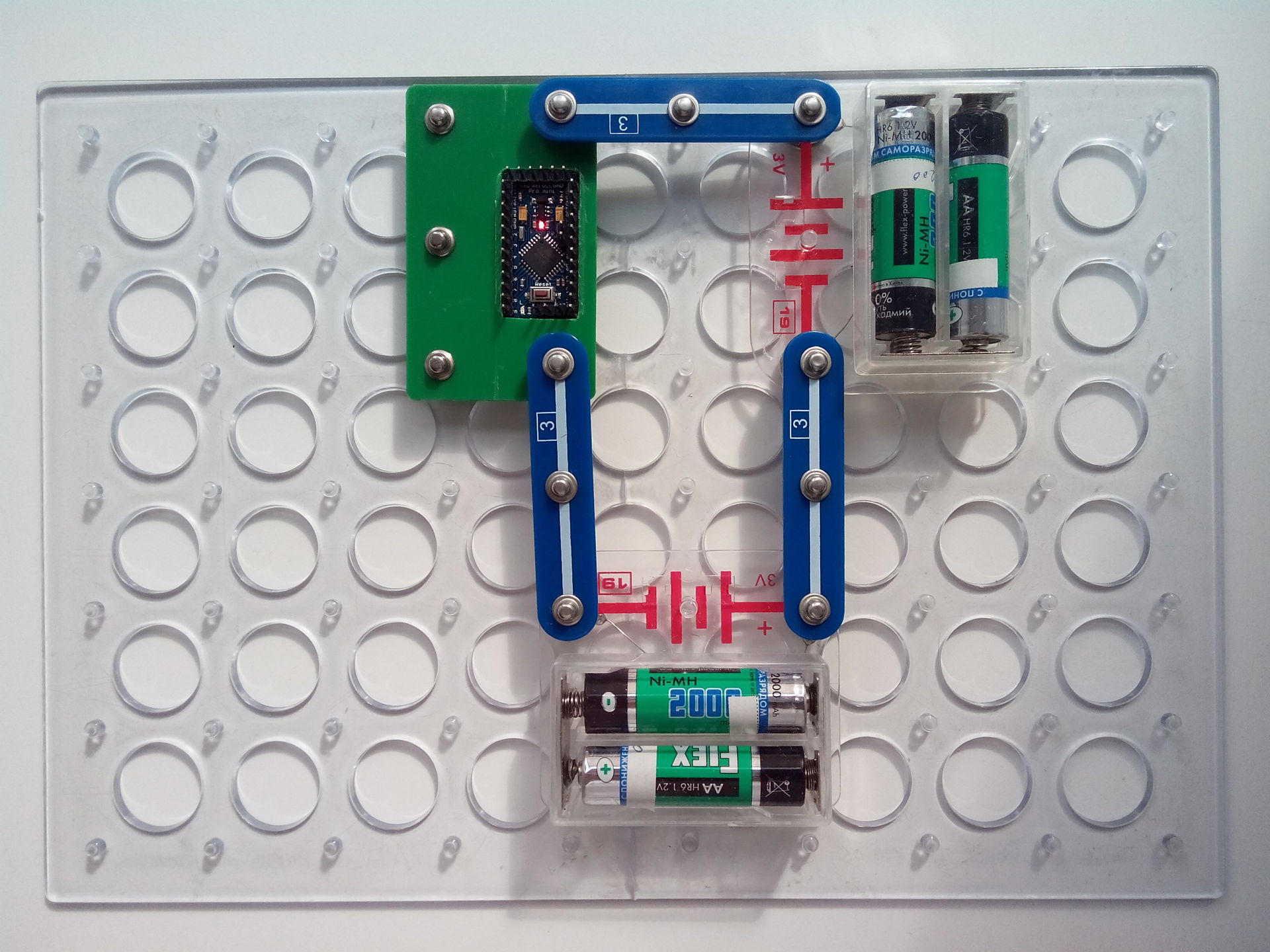
Fill the sketch of the traffic light. We collect the new scheme. We cling the wiring from the buttons to the appropriate legs. The Connoisseur kit contains only two LEDs, so I soldered the white-moon LED (there was no other at hand) into the base of the faulty light bulb. And enjoy!
The unit can be stored in a standard designer box, you just need to pull the wires out of the pins. (Or down pins, then you can not pull the wires).
It would be good to put the protection, Ohmov 20 on each of the three legs of the block, and provide a resurfacing. But the price of replacing the Arduino $ 3 is much lower than the bar of my laziness.
The new block of the designer "Expert" reanimated the child's interest in electronics. How now to name the new unit?
Amendment of 09/04/14.
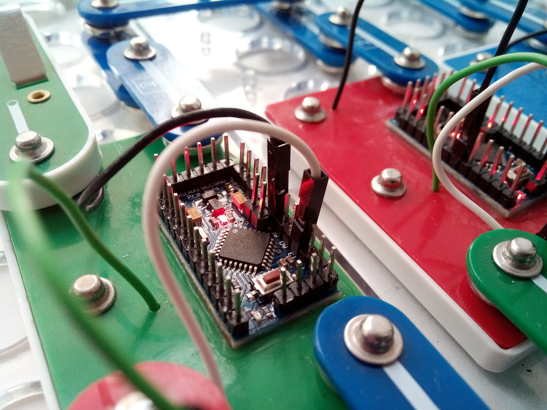
The support pin of the plastic base of the circuit board rests against the Arduino. Therefore, the board should be mounted on top of the unit, and not on the bottom, as described earlier. This option went into production:
I think I got a little carried away.
To be continued
Source: https://habr.com/ru/post/235461/
All Articles