We manage servos from OpenWRT without Arduino
A brief post on how to avoid unnecessary elements in the system with servos and use iron to the maximum
Prehistory
I have been very ill for a long time and have been ill with Linux, OpenWRT, network and wireless technologies, security, and now I’ve also slowly become infected with robotics and smart homes. All this is very cool, especially when there are so many ready-made templates, free and open source code, and sometimes you can completely go to the side of evil and quickly distribute logic to Scratch.
But then the interest wakes up is not just blinking LEDs, the wow effect passes and it is necessary to solve applied problems. It seems that here one should admire the abundance of the finished, but the devil, as always, is in the details. One thing is to control the logic
/ , it allows you to easily turn on or turn off the light, you can even pick up the air quality sensor (MQ-135) and turn on the hood if necessary. All this is cool, but in the 21st century, spacecraft are plying the big theater and the soul is asking for something cooler. My gaze fell on the control of servos. Why not? The topic is very broad, because they are present in many mechanisms, from robots to simple bottle openers. A plus is also the fact that in aircraft the engines are controlled in a similar way, and this expands the range of use just at times.Interested invite under the cat
Those who have long been familiar with the topic and want to go straight to the point - feel free to scroll to the section " Step-by-Step Instructions ".
')
Start over
So that the essence of this note is understandable to everyone, it is worth paying attention to the components of the servo drive first.

Electric motor, gearbox, potentiometer and controller. All ingenious is simple, isn't it?
To control the servo drive, pulse width modulation or PWM is used. Nothing complicated, it's just a signal in the form of rectangular pulses. The main parameters are the pulse width and the width of the "pause". "Pause", and it is better to call it correctly - the period, sets the frequency of the signal. Say, if we have a period width equal to 100 ms, then the frequency will be equal to 10 Hz. The calculation is very simple: we translate milliseconds into seconds and divide the unit by this number. Accordingly, 100ms = 0.1s and if 1 is divided by 0.1, we get 10. You can check on the calculator.
The width of the pulse sets the angle of rotation of the servo, and in the case of the engines of the aircraft sets the speed and direction of rotation.
Schematically, it looks like this:

And on the oscilloscope like this:

Now let's talk about how the servo perceives such a signal. And already the devil with details creeps.
The fact is that the controller can be digital or analog.
If in a very simple way, the difference is that the analog controller supplies or does not supply voltage only at the moment of impulse. By setting the pulse interval to 40, 120, or, say, 240 ms, you can notice how the servo starts to “twitch” during operation. All because there is a chip inside and the frequency of the entire servo is equal to the frequency of the external signal. Standard 20 ms is 50 Hz, 40 ms is 25 Hz, and by analogy. Accordingly, 50 or 25 times per second voltage is applied to the motor (or not). By reducing the frequency, it is possible to significantly reduce the torque and achieve a slower operation of the mechanism, although at the price of the “jerking” already described.
Digital controllers, as a rule, are a small microprocessor with strapping. The key difference from the analog chip is that the internal frequency of operation is constant. You can reduce the frequency of the control signal as much as you like, it will only affect the reaction time, but the torque will be constant. Although, issuing a change of position at long intervals and in small portions, it is possible to achieve a slow rotational speed. It already depends on the specific servo and its parameters.
How to generate a signal?
For this, they usually use some kind of microcontroller, a special love is fed to the Arduino platform. Everything is simple there. A ready-made library is used, we feed the necessary signal parameters and obtain pulses on a given GPIO of the desired width.
But what if there is no possibility to use a microcontroller interfaced with the main device, and the power of the controller itself for solving problems, well, is not enough in any way? It remains to seek alternatives. And I have such people!
As has already become clear from the title, the OpenWrt operating system will be used. Which is essentially a full-fledged distribution on the Linux kernel. And it gives ample opportunities and flexibility of setup. OpenWrt and its derivatives are actively used in various “smart home” systems, but this is covered in another article. How to generate a PWM (or bourgeois PWM) signal? It turns out, not much harder than the Arduino. To do this, you must use the same GPIO, and instead of the library, a kernel module called PWM-GPIO-Custom. The latest stable version of OpenWrt where it works is 12.09, but to understand this I spent about a week trying to make it work on the current Trunk. I do not know for what reason, but in the official repository of the package with this module is not and will have to collect it yourself, but it is not so difficult. Below I will write how.
Step-by-step instruction
So, first we need to download the OpenWrt build toolkit. Although, quite honestly, you need to start with the installation of Linux, but I hope that many of you have already done this point.
So, you have created a folder for the toolkit, moved into it
You can download the source code with the command
git clone git://git.openwrt.org/12.09/openwrt.gitYou have a terminal at the bottom of the window, right?
Sorry, it is very convenient.
After downloading, go to the openwrt folder and download the packages with the command
git clone git://git.openwrt.org/12.09/packages.gitNow we have all the source codes of the packages. But wait ... What about pwm-gpio-custom? He is not.
Do not despair, here he is
You just need to unpack the contents in openwrt / package and everything will be fine.
We now proceed directly to the assembly.
Being in the openwrt folder, you must run
make -jn kernel_menuconfigInstead of n, you need to substitute the number of your cores + 1.
A blue menu opens. Select the item Device Drivers.
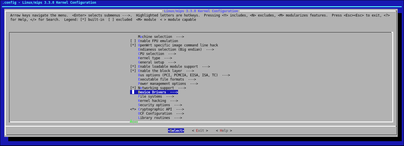
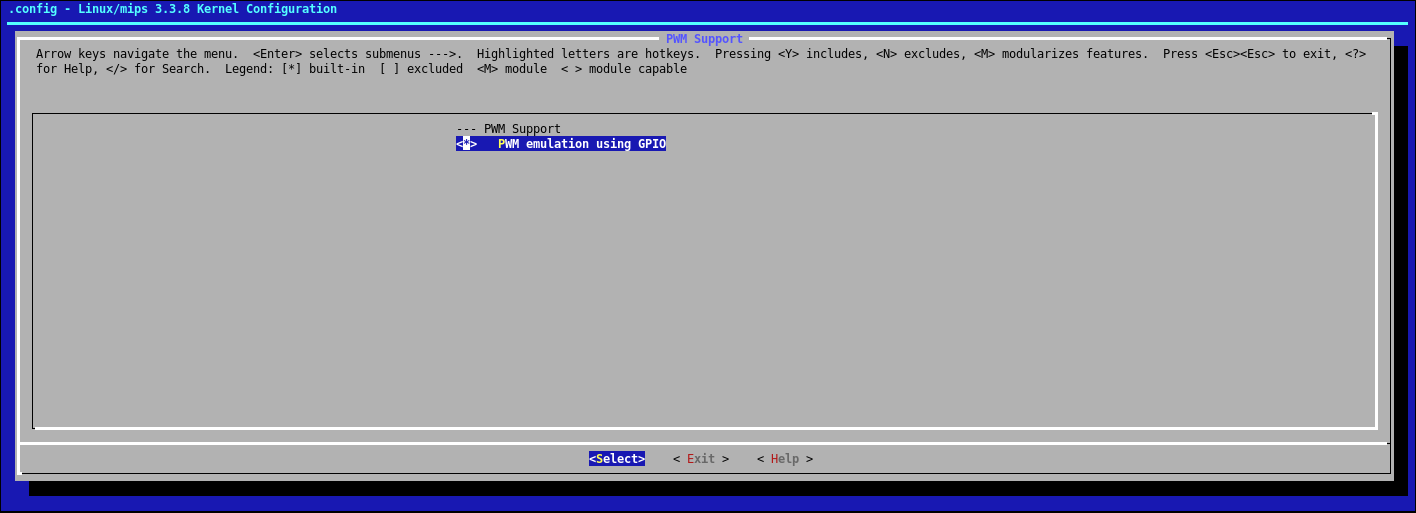
Find PWM Support:

Activate PWM emulation using GPIO. Select space. It is necessary that there were asterisks everywhere, this is important:
After that, you need to slightly reconfigure the kernel. We are looking for the appropriate item:

Put an asterisk on the High Resolution Timer Support item, set the Timer frequency value to 1000HZ, and in the Premption Model parameter, select Low-Latency Desktop:

You must surely know the hardware platform of your router. But more importantly, specify it in the configuration. I have this Atheros ar71xx:


The necessary kernel configuration is complete. Now, as soon as you click the final Exit, the system will ask you whether it is worth saving the changes, what you need to answer in the affirmative.
Now you need to configure the OS build itself using the same
make -jn menuconfigThen in the Kernel Modules menu:

Select Other modules:

And put an asterisk on kmod-pwm-gpio-custom:

Everything, it is possible to start assembly. All the same command
make -jnIt remains to sit back and see something, you can drink tea / coffee, the assembly process is not fast.
Once the build is complete, you can go to the bin folder. It will be a folder with your platform and images. You can sew in full compliance with standard instructions. As soon as the firmware process is completed, you can safely go through telnet. It will be necessary to additionally download the kmod-pwm-gpio-custom package onto the device itself. This can be done via SCP or via wget, or install openssh-sftp-server and use FileZilla.
It is better to load the package itself into the / tmp directory, since the ROM is not rubber, and this directory is physically located in the RAM, which is usually from 32 to 64 Mb. After downloading the package, you need to
opkg install /tmp/kmod-pwm-gpio-custom_xxx.ipk. You can strongly not bother with the name of the package, autocompletion for TAB works great.PWM signal generation
After installing the package, you can proceed to direct GPIO control and PWM signal generation.
To do this, you need to activate the kernel module. This can be done with the command
insmod pwm-gpio-custom bus0=0,23 bus1=1,20This is just an example of how it can be. busX sets the bus number that can be controlled via the character device under this same number in
/sys/lass/pwm We have two of them: gpio_pwm.0: 0 and gpio_pwm.1: 0 . You can manipulate the PWM parameters by simply writing the corresponding variables to files. Yes, I almost forgot, all values are given in nanoseconds. Go:echo 10000000 > /sys/class/pwm/gpio_pwm.0\:0/period_ns Sets the period. In this case, it is 100 Hz.echo 8500000 > /sys/class/pwm/gpio_pwm.0\:0/duty_ns Sets the duty cycle.Yes, some pins are inverted by default and you need to set the time of the “void” within the period. If the value of High for GPIO is 1, then you need to set
echo 1500000 > /sys/class/pwm/gpio_pwm.0\:0/duty_ns The time of the impulse itself will be indicated.You can check by experience. Maybe I will find or someone will tell a way to make it more beautiful =)
Now it remains only to activate the signal.
echo 1 > /sys/class/pwm/gpio_pwm.0\:0/run
If you connect a servo cable to the PWM pin, it will go straight to the center position. Of course, the power must also be connected.
Conclusion
In this way, it is possible to achieve the generation of a signal at a frequency of 200 Hz, and this means that the response time for one drive will decrease to 5 ms. For opening and closing the lock, maybe not critical, but for aircraft it will be very important. I hope that I will get a motor and a controller in the near future, or a kind reader from the city of Yekaterinburg will agree to lend me this for experiments and a second article will appear.
Thank you for reading to the end. For a snack, let me introduce you a little video.
Demonatration of work. Two channels tuned to the far right and leftmost position.
Video demonstration of PWM signal.
PS
I want to express my gratitude to the author of the module Claudio Mignanti , who answered by mail and explained the necessary questions.
The circuit of the servo and control signals were taken on wiki.amperka.ru .
If you have any additions or wishes - write in the comments.
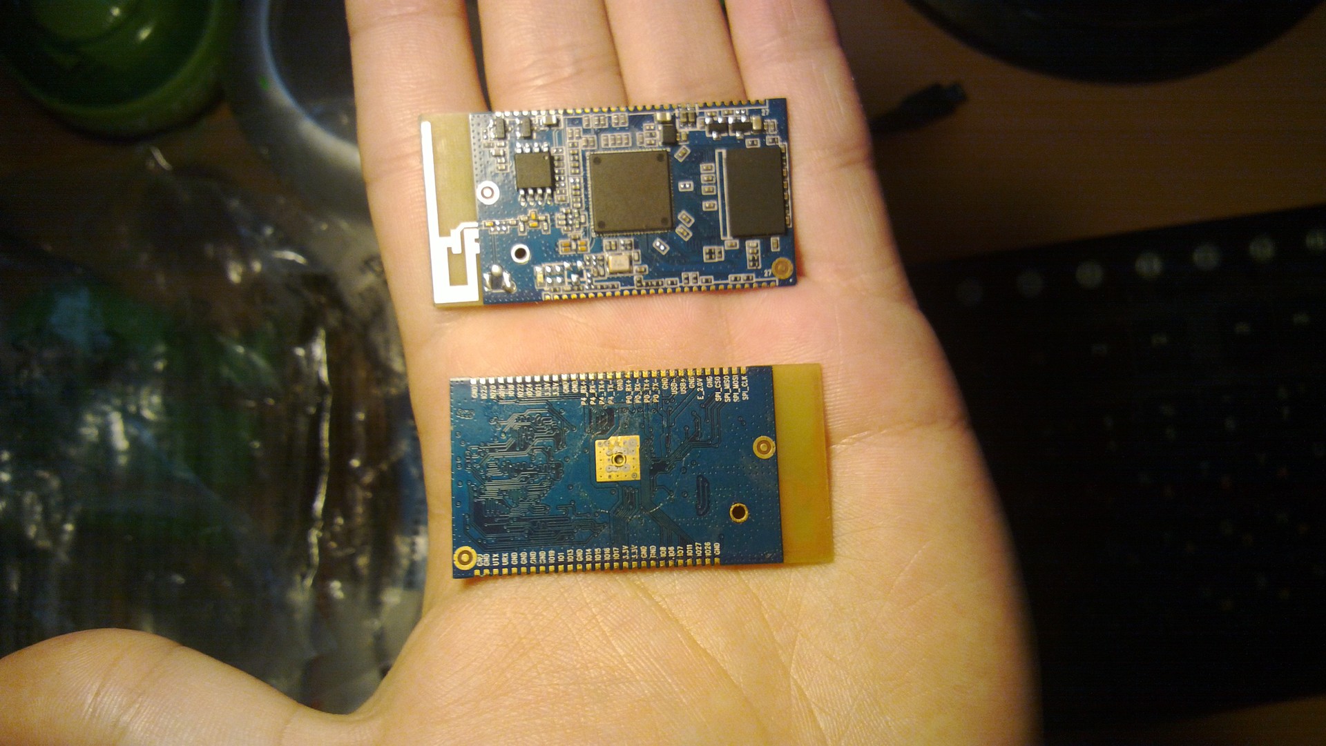
UPD: a5b wondered what device was used. Well, this is no secret. The board is a Chinese equivalent of EL-M150. The processor inside is the Atheros AR9331.
It is used very widely in such common routers as mr3020 or wr703n.
The board looks like this.
Source: https://habr.com/ru/post/235207/
All Articles