A few words about pipelines in FPGA
Hello!
Many people know that in all modern processors there is a computing pipeline. There is a misconception that the pipeline is some kind of chip processors, and in chips for other applications (for example, network) this is not. In fact, pipelining (or pipelining) is the key to building high-performance ASIC / FPGA applications.
Very often, to achieve high performance, such algorithms are chosen that are easily pipelined in the chip. If you are interested in learning about low-level details, welcome under the cat!
')
Consider the following example: it is necessary to sum four unsigned eight-bit numbers. Within the framework of this task, I neglected the fact that the result of summing up 8-bit numbers may be greater than 255.
Quite an obvious SystemVerilog code for this task:
Take a look at the resulting circuit of registers and adders. Use for this RTL Viewer in Quartus'e. (Tools -> Netlist Viewer -> RTL Viewer). In this article, the words "register" and "trigger" are fully-fledged synonyms.

What happened?
Add registers between the Add0 / Add1 and Add2 adders .

In order to see the difference in the behavior of the modules no_pipe_example and pipe_example combine them into one and simulate.
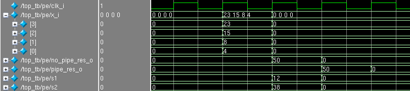
On the positive front (the so-called posedge) clk_i, 4 numbers were sent to the input of the module: 4, 8, 15 and 23. The next positive front in the no_pipe_res_o register appeared 50, and in the s1 and s2 registers the half sums are 12 and 38. Next posedge in the pipe_res_o register appeared the answer 50, and 0 appeared in no_pipe_res_o , which is not surprising, since four zeros were given as input values and the circuit honestly added them.
It is immediately noticeable that the result in pipe_res_o is delayed by one clock cycle than in no_pipe_res_o , since registers s1 and s2 were added.
Consider what happens if we each time we submit a new array of numbers for summation:
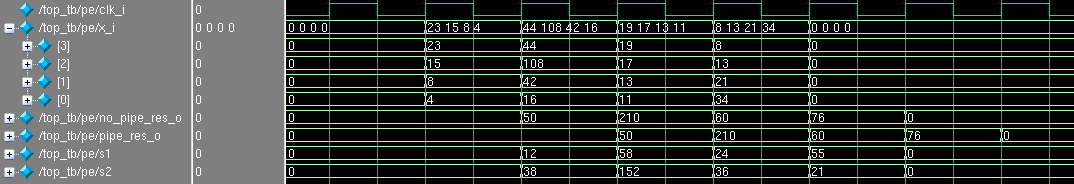
It is easy to see that both branches (with and without a pipeline) are ready for each new tact to receive each measure.
A fair question arises: why use a pipeline, if calculations take more time (cycles) and it takes more triggers (resources)?
The performance of this scheme is determined by the number of 8-bit fours, which it can accept and process per second. The circuit is ready for a new piece of data every clock; therefore, the higher the frequency value clk_i , the better the circuit performance.
There is a formula that calculates the maximum allowable frequency between two triggers. Its simplified version:

Legend :
Under the spoiler is a complete formula, an explanation of which can be found in the list of references, which is given at the end of the article.
To estimate the maximum frequency, paths are considered between all triggers within one clok domain: that is, only those triggers that run from the clock that interests us. Then the longest path is determined, which shows the maximum frequency at which the circuit will operate without errors.
The more logical elements in the signal path from one trigger to another, the greater the value of Tlogic . If we want to increase the frequency, then we need to reduce this value! How to do it?
Adding registers - this is pipelining! Pipelined circuits in most cases can operate at higher frequencies than those without a pipeline.
Consider the following example:
There are two triggers, A and B , the signal between them overcomes two “clouds” of logic, one of which takes 4 ns, the other 7 ns. If it is easier, imagine that the green cloud is an adder and the orange one is a multiplexer. Examples and numbers are taken from the head.

What will be equal to Fmax ? A sum of 4 and 7 ns will display the value of Tlogic : Fmax ~ 91 MHz.
Add a C register between the combination:

Fmax is estimated by the worst path, the time of which is now 7 ns, or ~ 142 MHz. Of course, do not rush and add registers to increase the frequency anywhere, because it is easy to run into the most frequent mistake (in my experience) that somewhere the circuit went for one clock cycle, since somewhere added a register, but somewhere not. It happens, the scheme for the pipeline was not ready, because There is a feedback, due to the delay per clock (s), it began to work incorrectly.
Let's summarize a little:
I note that sometimes the goal to achieve the maximum frequency is not, most often the opposite: the frequency is known, to which we must strive. For example, the standard frequency of 10G MAC-core is 156.25 MHz. It may be convenient for the whole circuit to operate from this frequency. There are requirements that are not directly related to the clock frequency: for example, there is a task for a search system to do 10 million searches per second. On the one hand, you can make a pipeline at a frequency of 10 MHz, and prepare a circuit to receive data every clock cycle. On the other, a more advantageous option may be this: increase the frequency to 100 MHz and make a pipeline that is ready to receive data every 10th clock cycle.
Of course, this example is very childish, but it is the key to creating circuits with very high performance.
In the last article I mentioned that I am developing high-speed Ethernet applications based on FPGA. The main basis of such applications are pipelines, which grind packages. It so happened that during the preparation of this article I gave a short lecture on pipelining in FPGA to student interns who are gaining experience in this craft. I thought that these tips would be appropriate here, and, perhaps, will cause some discussion. Experienced developers, most likely, will not find something new or original)
Sometimes novice FPGA developers make the following error: they determine the fact of the arrival of new data on the data itself. For example, they check the data for zero: if not zero, then the new data came, otherwise we do nothing. Also, instead of zero, they use some other “forbidden” combination (all units).
This is not a very correct approach, as:
By entering validity signals, we inform the module of the fact of the presence of valid data at the input, and it in turn shows when the data at the output is correct. These signals can use the following module, which stands in a conveyor chain.
Add the validity signals x_val_i and pipe_res_val_o to the example above:
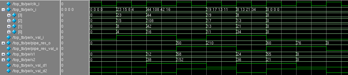
You must admit that it immediately became clearer what is happening here: at what cycle are the input and output data valid?
A couple of comments:
Most often, when developing, it is immediately clear that it is necessary to build a pipeline to achieve the desired frequency. When a pipeline is written from scratch, you need to think about the architecture, for example, decide when you can send data to the pipeline. By way of illustration, here is a typical Ethernet pipeline processing architecture.

Legend:
In this example, fifo_0 is the sender of the data, and fifo_1 is the receiver. Suppose that for some reason data is not read out from fifo_1 or data reading speed is lower than the write speed, as a result, this fifo may overflow. It is not necessary to write in full fifoshku, because, at least, you break the package (some data set may disappear from the package) and transfer it incorrectly.
What can fifo say?
In order not to break the data, we need once to not read package data from fifo_0 and suspend the operation of the pipeline. How to do it?
Suppose we allocated fifo_1 for MTU, for example, 1500 bytes. Before starting to read a packet from fifo_0, arb looks at the number of free bytes in fifo_1 . If it is larger than the size of the current package, then set rd_req and do not remove it to the end of the package. Otherwise, wait until the fifo is released.
Pros:
Minuses:
Note:
When calculating the free space you need to make a margin for the length of the conveyor. For example, right now in fifo_1 100 bytes are free, a packet of 95 bytes has come to us. We look that 100 is more than 95 and start forwarding the packet. This is not entirely true. we do not know the current state of the pipeline - if we process the previous packet, then in the worst case, in fifo_1, additional words will be written in the amount of the length of the pipeline (in cycles). If the pipeline is working 10 cycles, then another 10 words will fall into fifo_1 , and the fifo may overflow when we write a packet of 95 bytes.
We reserve in fifo_1 the number of words equal to the length of the conveyor. We use the almost_full signal.
The arbitrator watches every signal on this signal. If it is 0, then we read one word of the package, otherwise - no.
Pros:
Minuses:
The previous options have a common feature: if the word of the package got to the beginning of the pipeline, then nothing can be done: through a constant number of ticks this word (or its modification) will fall into fifo_1 .
An alternative option is that the conveyor can be stopped during operation. Each stage with the number M appears ready input, which shows whether stage M + 1 is ready to receive data or not. At the entrance of the latest stage, the inversion is full or almost_full (if there is a desire to be safe a little).

Pros :
Minuses:
The above problems can be resolved using interfaces that already contain auxiliary signals. Altera for data streams suggests using Avalon Streaming interface ( Avalon-ST ). Its detailed description can be found here . By the way, this interface is used in Alterovsky 10G / 40G / 100G Ethernet MAC cores.

Immediately draws attention to the presence of signals valid and ready , about which we spoke earlier. The empty signal indicates the number of free (unused) bytes in the last word of the packet. The startofpacket and endofpacket signals determine the beginning and end of the packet: it is convenient to use these signals to reset various counters that count offsets to get the necessary data.
Xilinx proposes using the AXI4-Stream for this purpose.

In general, the set of signals is similar (in this picture, not all signals are possible available in this standard). To be honest, I have never used AXI4-Stream. If someone has used both interfaces, I would appreciate if you share the comparison and impressions.
I think the advantages of using standard interfaces should not be mentioned. Well, the drawbacks are obvious: it is necessary to comply with the standard, which is expressed in more code, resources, tests, etc. Of course, you can make your bikes, but in the long run on a large project (and top-end chips) this can get sideways.
As an example, it is more complicated than a pair of adders, I propose to make a module that in the Ethernet packet swaps the source and destination MAC addresses ( mac_src and mac_dst ). This can be useful if you want all the traffic that comes to the device to send back (the so-called traffic invert / loop or loopback). Implementation, of course, must be done with a pipeline.
We use the Avalon-ST interface with a 64-bit data bus (for 10G) without ready and error signals. As a test package, take the one that looked at xgmii in the previous article . Then:
Code on SystemVerilog under the spoiler:
Not everything is as scary as it might have seemed before: most of the lines went to the description of the inputs / outputs of the module and the delay line. By startofpacket, we define in which word we are, and what data should be substituted into the new_data_c , which is then clicked into the data_o . The startofpacket , endofpacket , empty , valid signals are delayed by the desired number of ticks.
Module simulation:
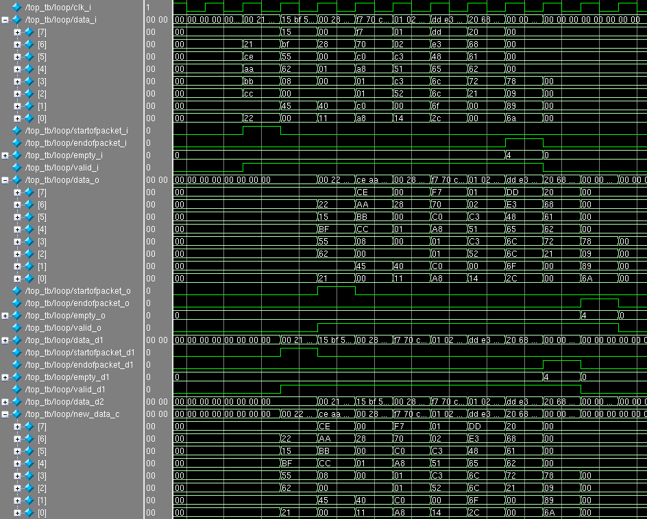
As you can see, the MAC addresses are swapped, and all other data in the package has not changed.
In the next article, we will examine the quadtree : a more serious example of pipelining, where we use one of the architectural features of FPGA - block memory.
Thanks for your time and attention! If you have questions, ask without a doubt.
PS I thank des333 for constructive criticism and advice.
Many people know that in all modern processors there is a computing pipeline. There is a misconception that the pipeline is some kind of chip processors, and in chips for other applications (for example, network) this is not. In fact, pipelining (or pipelining) is the key to building high-performance ASIC / FPGA applications.
Very often, to achieve high performance, such algorithms are chosen that are easily pipelined in the chip. If you are interested in learning about low-level details, welcome under the cat!
')
Simple example
Consider the following example: it is necessary to sum four unsigned eight-bit numbers. Within the framework of this task, I neglected the fact that the result of summing up 8-bit numbers may be greater than 255.
Quite an obvious SystemVerilog code for this task:
module no_pipe_example( input clk_i, input [7:0] x_i [3:0], output logic [7:0] no_pipe_res_o ); // no pipeline always_ff @( posedge clk_i ) begin no_pipe_res_o <= ( x_i[0] + x_i[1] ) + ( x_i[2] + x_i[3] ); end endmodule Take a look at the resulting circuit of registers and adders. Use for this RTL Viewer in Quartus'e. (Tools -> Netlist Viewer -> RTL Viewer). In this article, the words "register" and "trigger" are fully-fledged synonyms.

What happened?
- The inputs x_i [0] and x_i [1] are fed to the adder Add0 , and x_i [2] and x_i [3] to Add1 .
- Outputs with Add0 and Add1 are fed to the Add2 adder.
- The output from the Add2 adder is latched into the trigger no_pipe_res_o .
Add registers between the Add0 / Add1 and Add2 adders .
module pipe_example( input clk_i, input [7:0] x_i [3:0], output logic [7:0] pipe_res_o ); // pipeline logic [7:0] s1 = '0; logic [7:0] s2 = '0; always_ff @( posedge clk_i ) begin s1 <= x_i[0] + x_i[1]; s2 <= x_i[2] + x_i[3]; pipe_res_o <= s1 + s2; end endmodule 
- The inputs x_i [0] and x_i [1] are fed to the adder Add0 , and x_i [2] and x_i [3] to Add1 .
- After summation, the result is put into registers s1 and s2 .
- The data from the registers s1 and s2 are fed to Add2 , the result of summation is latched into pipe_res_o .
In order to see the difference in the behavior of the modules no_pipe_example and pipe_example combine them into one and simulate.
Hidden text
module pipe_and_no_pipe_example( input clk_i, input [7:0] x_i [3:0], output logic [7:0] no_pipe_res_o, output logic [7:0] pipe_res_o ); // no pipeline always_ff @( posedge clk_i ) begin no_pipe_res_o <= ( x_i[0] + x_i[1] ) + ( x_i[2] + x_i[3] ); end // pipeline logic [7:0] s1 = '0; logic [7:0] s2 = '0; always_ff @( posedge clk_i ) begin s1 <= x_i[0] + x_i[1]; s2 <= x_i[2] + x_i[3]; pipe_res_o <= s1 + s2; end endmodule 
On the positive front (the so-called posedge) clk_i, 4 numbers were sent to the input of the module: 4, 8, 15 and 23. The next positive front in the no_pipe_res_o register appeared 50, and in the s1 and s2 registers the half sums are 12 and 38. Next posedge in the pipe_res_o register appeared the answer 50, and 0 appeared in no_pipe_res_o , which is not surprising, since four zeros were given as input values and the circuit honestly added them.
It is immediately noticeable that the result in pipe_res_o is delayed by one clock cycle than in no_pipe_res_o , since registers s1 and s2 were added.
Consider what happens if we each time we submit a new array of numbers for summation:

It is easy to see that both branches (with and without a pipeline) are ready for each new tact to receive each measure.
A fair question arises: why use a pipeline, if calculations take more time (cycles) and it takes more triggers (resources)?
Conveyor capacity
The performance of this scheme is determined by the number of 8-bit fours, which it can accept and process per second. The circuit is ready for a new piece of data every clock; therefore, the higher the frequency value clk_i , the better the circuit performance.
There is a formula that calculates the maximum allowable frequency between two triggers. Its simplified version:

Legend :
- Fmax - the maximum clock frequency.
- Tlogic - the delay in the passage of a signal through the logic elements.
Under the spoiler is a complete formula, an explanation of which can be found in the list of references, which is given at the end of the article.
Hidden text

To estimate the maximum frequency, paths are considered between all triggers within one clok domain: that is, only those triggers that run from the clock that interests us. Then the longest path is determined, which shows the maximum frequency at which the circuit will operate without errors.
The more logical elements in the signal path from one trigger to another, the greater the value of Tlogic . If we want to increase the frequency, then we need to reduce this value! How to do it?
- Optimize code. Sometimes newbies (and experienced developers, to be honest!) Write such constructs that turn into very long chains of logic: this should be avoided with various tricks. Sometimes it is necessary to optimize the circuit for a specific FPGA architecture.
- Add register (s). Just cut the logic into pieces.
Adding registers - this is pipelining! Pipelined circuits in most cases can operate at higher frequencies than those without a pipeline.
Consider the following example:
There are two triggers, A and B , the signal between them overcomes two “clouds” of logic, one of which takes 4 ns, the other 7 ns. If it is easier, imagine that the green cloud is an adder and the orange one is a multiplexer. Examples and numbers are taken from the head.

What will be equal to Fmax ? A sum of 4 and 7 ns will display the value of Tlogic : Fmax ~ 91 MHz.
Add a C register between the combination:

Fmax is estimated by the worst path, the time of which is now 7 ns, or ~ 142 MHz. Of course, do not rush and add registers to increase the frequency anywhere, because it is easy to run into the most frequent mistake (in my experience) that somewhere the circuit went for one clock cycle, since somewhere added a register, but somewhere not. It happens, the scheme for the pipeline was not ready, because There is a feedback, due to the delay per clock (s), it began to work incorrectly.
Let's summarize a little:
- Through pipelining, you can increase the throughput of the circuit by sacrificing processing time and resources.
- It is necessary to break the logic as evenly as possible, since maximum frequency of the circuit depends on the worst path. Smashing 11 ns in half, it would be possible to get 182 MHz.
- Of course, to infinity increase the frequency does not work, because Temporary parameters, which we have now closed our eyes, can not be neglected. Trouting first.
I note that sometimes the goal to achieve the maximum frequency is not, most often the opposite: the frequency is known, to which we must strive. For example, the standard frequency of 10G MAC-core is 156.25 MHz. It may be convenient for the whole circuit to operate from this frequency. There are requirements that are not directly related to the clock frequency: for example, there is a task for a search system to do 10 million searches per second. On the one hand, you can make a pipeline at a frequency of 10 MHz, and prepare a circuit to receive data every clock cycle. On the other, a more advantageous option may be this: increase the frequency to 100 MHz and make a pipeline that is ready to receive data every 10th clock cycle.
Of course, this example is very childish, but it is the key to creating circuits with very high performance.
Tips and personal experience
In the last article I mentioned that I am developing high-speed Ethernet applications based on FPGA. The main basis of such applications are pipelines, which grind packages. It so happened that during the preparation of this article I gave a short lecture on pipelining in FPGA to student interns who are gaining experience in this craft. I thought that these tips would be appropriate here, and, perhaps, will cause some discussion. Experienced developers, most likely, will not find something new or original)
Use validity cues
Sometimes novice FPGA developers make the following error: they determine the fact of the arrival of new data on the data itself. For example, they check the data for zero: if not zero, then the new data came, otherwise we do nothing. Also, instead of zero, they use some other “forbidden” combination (all units).
This is not a very correct approach, as:
- Resources are spent on zeroing and checking. On large data buses, this can be very expensive.
- It may not be obvious to other developers what is happening here (WTF code).
- Some kind of forbidden combination may not be. As in the example with the adder above: all values from 0 to 255 are valid and can be fed to the adder.
By entering validity signals, we inform the module of the fact of the presence of valid data at the input, and it in turn shows when the data at the output is correct. These signals can use the following module, which stands in a conveyor chain.
Add the validity signals x_val_i and pipe_res_val_o to the example above:
Hidden text
module pipe_with_val_example( input clk_i, input [7:0] x_i [3:0], input x_val_i, output logic [7:0] pipe_res_o, output logic pipe_res_val_o ); logic [7:0] s1 = '0; logic [7:0] s2 = '0; logic x_val_d1 = 1'b0; logic x_val_d2 = 1'b0; always_ff @( posedge clk_i ) begin x_val_d1 <= x_val_i; x_val_d2 <= x_val_d1; end always_ff @( posedge clk_i ) begin s1 <= x_i[0] + x_i[1]; s2 <= x_i[2] + x_i[3]; pipe_res_o <= s1 + s2; end assign pipe_res_val_o = x_val_d2; endmodule 
You must admit that it immediately became clearer what is happening here: at what cycle are the input and output data valid?
A couple of comments:
- In this example, it would be nice to add a reset , so that he would reset x_val_d1 / d2 .
- Despite the fact that the data is invalid, the adders still add them and put the data in the registers. On the other hand, one would be allowed to save to registers only when the data is valid. In this example, saving invalid data does not lead to anything bad: I didn’t add permission to work. However, if there is a need to optimize for power consumption, you will have to add such signals and simply do not drive the current :).
Think about the sender and the data recipient
Most often, when developing, it is immediately clear that it is necessary to build a pipeline to achieve the desired frequency. When a pipeline is written from scratch, you need to think about the architecture, for example, decide when you can send data to the pipeline. By way of illustration, here is a typical Ethernet pipeline processing architecture.

Legend:
- fifo_0 , fifo_1 - fifoshki to accommodate the package data. In this example, it is assumed that before the start of reading from fifo_0 the entire package is already placed there, and the logic behind fifo_1 does not require a whole package to start processing.
- arb is the arbiter who decides when to read the data from fifo_0 and to submit to the input of module A. Subtraction is performed by setting the signal rd_req (read request).
- A , B , C - abstract modules that form a conveyor chain. It is not at all necessary that each module processes the data one clock cycle. The modules inside can also be pipelined. They perform some kind of packet processing, for example, they form a system of parsers or modify a packet (for example, they substitute the source or destination MAC addresses).
In this example, fifo_0 is the sender of the data, and fifo_1 is the receiver. Suppose that for some reason data is not read out from fifo_1 or data reading speed is lower than the write speed, as a result, this fifo may overflow. It is not necessary to write in full fifoshku, because, at least, you break the package (some data set may disappear from the package) and transfer it incorrectly.
What can fifo say?
- used_words is the number of words used. Knowing the size of the fiesta, you can calculate the number of free words. In this example, we assume that one word is equal to one byte.
- full and almost_full - signals that the fifo has already filled, or "almost" filled. “Almost” is determined by the custom boundary of the words used.
In order not to break the data, we need once to not read package data from fifo_0 and suspend the operation of the pipeline. How to do it?
Forehead algorithm
Suppose we allocated fifo_1 for MTU, for example, 1500 bytes. Before starting to read a packet from fifo_0, arb looks at the number of free bytes in fifo_1 . If it is larger than the size of the current package, then set rd_req and do not remove it to the end of the package. Otherwise, wait until the fifo is released.
Pros:
- Arbitration is relatively simple and done quickly.
- Fewer boundary conditions to check.
Minuses:
- fifo_1 must be allocated for MTU. And if you have an MTU 64K, then a couple of such fifo will give you half FPGA). Sometimes it is impossible to get by without the fifo for a package, but it’s better to save resources.
- If the conveyor is idle, because space for the whole package is not enough, then we lose in performance. More precisely, the worst case (the overflow of fifo_0 , in which someone also puts packages) comes faster.
Note:
When calculating the free space you need to make a margin for the length of the conveyor. For example, right now in fifo_1 100 bytes are free, a packet of 95 bytes has come to us. We look that 100 is more than 95 and start forwarding the packet. This is not entirely true. we do not know the current state of the pipeline - if we process the previous packet, then in the worst case, in fifo_1, additional words will be written in the amount of the length of the pipeline (in cycles). If the pipeline is working 10 cycles, then another 10 words will fall into fifo_1 , and the fifo may overflow when we write a packet of 95 bytes.
Improving the "algorithm in the forehead"
We reserve in fifo_1 the number of words equal to the length of the conveyor. We use the almost_full signal.
The arbitrator watches every signal on this signal. If it is 0, then we read one word of the package, otherwise - no.
Pros:
- Fifo_1 may not be very big, for example, a couple of dozen words.
Minuses:
- Modules A , B , C must be prepared for the fact that a packet will come not every clock cycle, but in parts. If more formally: the validity signal inside the packet may be interrupted.
- Need to check more boundary conditions.
- If new pipeline stages are added (hence, its length increases), then you can forget to reduce the upper limit in fifo_1 . Or it is necessary somehow to calculate this border with the parameter, which can be nontrivial.
Stopping the conveyor during operation
The previous options have a common feature: if the word of the package got to the beginning of the pipeline, then nothing can be done: through a constant number of ticks this word (or its modification) will fall into fifo_1 .
An alternative option is that the conveyor can be stopped during operation. Each stage with the number M appears ready input, which shows whether stage M + 1 is ready to receive data or not. At the entrance of the latest stage, the inversion is full or almost_full (if there is a desire to be safe a little).

Pros :
- You can painlessly add new pipeline stages.
- Each stage may now have nuances in the work, but there is no need to redesign the architecture. For example: we wanted to add some VLAN-tag to the packet before putting the packet in fifo_1 . VLAN-tag is 4 bytes, in our case - 4 words. If the packets go one after the other, then in the first two cases, arb should have realized that after the end of the packet, it was necessary to pause 4 cycles, since package will increase by 4 words. In this case, everything will be adjusted by itself and the module that inserts the VLAN at the time of its insertion will set ready to zero at the stage of the pipeline that stands before it.
Minuses:
- The code gets more complicated.
- During verification, it is necessary to check even more boundary conditions.
- Most likely it takes more resources than previous versions.
Use standardized interfaces
The above problems can be resolved using interfaces that already contain auxiliary signals. Altera for data streams suggests using Avalon Streaming interface ( Avalon-ST ). Its detailed description can be found here . By the way, this interface is used in Alterovsky 10G / 40G / 100G Ethernet MAC cores.

Immediately draws attention to the presence of signals valid and ready , about which we spoke earlier. The empty signal indicates the number of free (unused) bytes in the last word of the packet. The startofpacket and endofpacket signals determine the beginning and end of the packet: it is convenient to use these signals to reset various counters that count offsets to get the necessary data.
Xilinx proposes using the AXI4-Stream for this purpose.

In general, the set of signals is similar (in this picture, not all signals are possible available in this standard). To be honest, I have never used AXI4-Stream. If someone has used both interfaces, I would appreciate if you share the comparison and impressions.
I think the advantages of using standard interfaces should not be mentioned. Well, the drawbacks are obvious: it is necessary to comply with the standard, which is expressed in more code, resources, tests, etc. Of course, you can make your bikes, but in the long run on a large project (and top-end chips) this can get sideways.
Bonus
As an example, it is more complicated than a pair of adders, I propose to make a module that in the Ethernet packet swaps the source and destination MAC addresses ( mac_src and mac_dst ). This can be useful if you want all the traffic that comes to the device to send back (the so-called traffic invert / loop or loopback). Implementation, of course, must be done with a pipeline.
We use the Avalon-ST interface with a 64-bit data bus (for 10G) without ready and error signals. As a test package, take the one that looked at xgmii in the previous article . Then:
- mac_dst - 00: 21: CE: AA: BB: CC (bytes 0 to 5). Located in the 0 word in bytes 7: 2.
- mac_src - 00: 22: 15: BF: 55: 62 (bytes 6 to 11). Is located in the 0 word in bytes 1: 0 and in 1 word in bytes 7: 4.
Code on SystemVerilog under the spoiler:
Hidden text
module loop_l2( input clk_i, input rst_i, input [7:0][7:0] data_i, input startofpacket_i, input endofpacket_i, input [2:0] empty_i, input valid_i, output logic [7:0][7:0] data_o, output logic startofpacket_o, output logic endofpacket_o, output logic [2:0] empty_o, output logic valid_o ); logic [7:0][7:0] data_d1; logic startofpacket_d1; logic endofpacket_d1; logic [2:0] empty_d1; logic valid_d1; logic [7:0][7:0] data_d2; logic [7:0][7:0] new_data_c; always_ff @( posedge clk_i or posedge rst_i ) if( rst_i ) begin data_d1 <= '0; startofpacket_d1 <= '0; endofpacket_d1 <= '0; empty_d1 <= '0; valid_d1 <= '0; data_o <= '0; startofpacket_o <= '0; endofpacket_o <= '0; empty_o <= '0; valid_o <= '0; data_d2 <= '0; end else begin data_d1 <= data_i; startofpacket_d1 <= startofpacket_i; endofpacket_d1 <= endofpacket_i; empty_d1 <= empty_i; valid_d1 <= valid_i; data_o <= new_data_c; startofpacket_o <= startofpacket_d1; endofpacket_o <= endofpacket_d1; empty_o <= empty_d1; valid_o <= valid_d1; data_d2 <= data_d1; end always_comb begin new_data_c = data_d1; if( startofpacket_d1 ) begin new_data_c = { data_d1[1:0], data_i[7:4], data_d1[7:6] }; end else if( startofpacket_o ) begin new_data_c[7:4] = data_d2[5:2]; end end endmodule Not everything is as scary as it might have seemed before: most of the lines went to the description of the inputs / outputs of the module and the delay line. By startofpacket, we define in which word we are, and what data should be substituted into the new_data_c , which is then clicked into the data_o . The startofpacket , endofpacket , empty , valid signals are delayed by the desired number of ticks.
Module simulation:

As you can see, the MAC addresses are swapped, and all other data in the package has not changed.
In the next article, we will examine the quadtree : a more serious example of pipelining, where we use one of the architectural features of FPGA - block memory.
Thanks for your time and attention! If you have questions, ask without a doubt.
Bibliography
- Advanced FPGA Design is one of the best FPGA books I've ever seen. Chapter 1 covers pipelining in detail. IMHO, the book is for those who have already received some experience in FPGA development and want to systematize their knowledge or some intuitive guesswork.
- TimeQuest Timing Analyzer is an application for estimating the value of timings (including Fmax ) for Altera FPGAs.
PS I thank des333 for constructive criticism and advice.
Source: https://habr.com/ru/post/235037/
All Articles