Mini airship control system
Good afternoon, dear reader, you are presented with a project to develop a touch control system for a mini-dirigible balloon.
The control task is to move the airship along the line. A simple remote control system was also implemented.
The object of control is a mini-airship developed at the Department of E & M, TIT SFU.
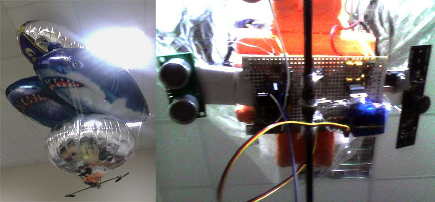
Figure 1 - General view of the mini-airship.
The project aims: development of a technical vision system for line detection (motion path); development of the course regulator, taking into account the factors of the position of the line and the angle of inclination of the line relative to the airship; development of height adjuster; development of a remote control system.
The development of a touch control system is based on a mini-airship designed at the E & M department.
The mini-airship includes a shell on commonly available components, namely a variety of foil balloons.
')
The hardware part of the mini-airship consists of
Rotate the mini-airship around the vertical axis is raznotyagiem engines. The height adjustment of the airship is carried out by the deviation of the thrust vector of the engines along the vertical axis.
Airship engines have the ability to set the maximum speed to 3200 rpm. / min The operating voltage of the motors is 7.4 volts. The engines are separated from the center of the airship by 25 cm, and are located at the lower point of the airship.

Figure 2 - Block diagram of the vision system of a mini-airship.
The vision system consists of hardware and software parts. The hardware is connected to the software by a wired connection, where the already generated MJPG format signal is transmitted.
The hardware includes a webcam.
The program part includes:
Taking into account the selected method of processing and the algorithm for determining the location of the line (which will be discussed in the next chapter), the following tasks were identified in the software implementation:
Getting the image from the camera and converting it to the HSV color format is entrusted to the opencv library.
As is known, a straight line can be laid through any two points in space. In this case, the vision system of the mini-airship is tasked with determining the laid line. The first stage of image processing will be the search for these two points through which our line was laid.
We define the zones of interest in our image to search for these points. The optimal location of the zone of interest will be the intervals between 1/3 of the vertical part of the frame and 2/3. as shown in Figure 4 by the blue lines.

Figure 3 - The optimal location of the zone of interest.
The criterion for the optimal location of the zone of interest is that the lower part of the zone of interest is perpendicular down from the mini-airship, and the upper part is not at the frame boundary, which minimizes distortion of the resulting image of the zone.
The height of each zone is 10 pixels.
The point of intersection with the line is determined by matching the pixels to the specified color. The color space of the vision system HSV.
2 stages of the algorithm with each zone of interest.
1. The determination of compliance with a given color occurs in an array, the width of which is the width of the frame received from the camera. Each element of the array is an average of 10 pixels in a column of interest. Thus the color noise coming from the camera is averaged. The array has 3 lines, each of which corresponds to HSV channels. At the output, we get a one-dimensional array, in which the value “1” denotes pixel addresses corresponding to the specified color, the value “0” denotes pixel addresses that do not correspond to the specified color.
2. Determination of the left and right border of the intersection zone.
On the input array two arrays of the same dimension are filled. Let's call them st1 and st2. The array filling algorithm is implemented by a cycle in which some variable increases linearly if the considered element of the input array is 1, and exponentially decreases if the element in question is 0, and is written to the next element of the array st1. To form the st2 array, the input array is considered from the end. As a result, arrays of st1 and st2 can be represented graphically as follows (Fig. 5)

Figure 5 - Graphic representation of the st1 and st2 arrays.
A useful signal is the widest color detection area. Noise is a small false positives, which can be observed at figure 7. The coordinates x of the maximum element of the red graph (st1), is the right side of the line crossing the zone of interest. The x coordinates of the maximum element of the blue graph (st2) is the left side of the line crossing the zone of interest.
Listing
After the formation of the arrays st1 and st2, the maximum elements of the array are found, and the center of the intersection zone is calculated. Applying all the described actions to the second intersection zone, at the exit we have the coordinates of the points through which the line passes.
The application of the common method, determining the zone of confidence in the next frame, according to the state of the object in the previous one, was not used, since this method also showed acceptable results of noise in the output parameters. Also, the application of this method would not reduce the processor load, since we are dealing only with repeated enumeration of two arrays with a width of 176 pixels, the resolution of the entire image is 176x144 pixels.
Figure 4 - Block diagram of the directional controller.
Software implementation consists of:
The hardware part of the Raspberry pi consists of the bcm2835 processor, which connects the gpio conclusions on the results of the work of the program ShIM.
Hardware implementation consists of:
The block diagram of the directional regulator consists of the program part based on a fuzzy regulator. The algorithm for dephasing is the Mamdani algorithm.
The use of software PWM is caused by the absence of hardware PWM in the single-board computer Raspberry pi used.
Motor driver is used to amplify the PWM signal.
Since for accurate passage of a mini-airship along a line, it is necessary to take into account both the deviations of the line from the axis of the airship, and the rotation about the same axis, respectively, the variable parameters of the regulator (OFF) and turn (DOM) will be set by the controller input parameters. The output variables of the controller will be the parameters of the output PWM signal as a percentage. The output variable of the impact on the left engine is designated as (LEV), the right engine, respectively (RIGHT)
The output terms of the left and right motor accessories would have to be set, would appear as non-linear parameters of the DC motor operation with respect to the PWM effect. But since the airship speeds suggest a small linear deviation of the engines, the terms were set as for an ideal engine with an absolute linear characteristic.
Figure 5 - Terms of output variables LEV and RIGHTS.
The input variable deviations of the longitudinal axis of the airship from the line and the rotation of the line from the same axis are obtained as a result of the work of the vision system and the mathematical module for calculating the angle, the camera of which has distortion indices. The camera distortion values can be set in the input terms OFF and STB. Since there are no requirements for the positioning accuracy and the trajectory of the output to the line, distortion indicators can be ignored. In this assignment, the therm tuned the distortion pictures of the camera and the terms on them were not tuned. Terms were changed approximately, which was a sufficient condition for the functioning of the system.
Figure 6 - Term OFF and Stand.
To develop a rule base, it is necessary to designate linguistic variables (terms) with easy-to-understand names.
Figure 7 - Term designation.
Accordingly, these names, given that the mini-airship is controlled by raznotyag on the engines we establish the connection term.
rule block:
You may notice that for the input variable, there is no connectedness of averages. This is due to the fact that with the correct orientation of the longitudinal axis of the airship relative to the line and deviations from it, the average term pulled the input values of the motors to the middle, which is incorrect in this position of the airship.
In this fuzzy system, the dephasing algorithm is the Mamdani algorithm.
This algorithm describes several successive stages, with each subsequent stage receiving the values obtained in the previous step as input.
To analyze the process of work. Were built correlation portraits of the regulator. In the figures below, the Y axis is the input variable DOM, the X axis is the input variable OFF. The color of the pixel corresponds to the input variable of each engine, white is the minimum, and black is the maximum.
Figure 8 - Correlation portraits of the output value of a fuzzy system for the left and right engines, the intersection of correlation portraits.
In the last figure, we see the result of the intersection of two correlation portraits with the application of the selection pixel with the same color and location. From the result of the intersection, it is possible to determine under what input conditions the same engine power values will be. The characteristic black square areas at the edges give marginal terms with a truncated tip.
Below are the results of emulation of a fuzzy regulator relative to the location of the line in the frame indicated in red. On the right side of the video, you can observe the PWM signal levels for the left and right motor, respectively. On the left side are the input and output terms of accessories.
Figure 9 - Block diagram of the height regulator.
Software implementation consists of:
The hardware part of the Raspberry pi consists of a bcm2835 processor, connecting gpio conclusions on the results of software PWM.
The hardware implementation consists of
The input parameter of the fuzzy part of the regulator is the error from the desired height. The output variable is the proportional part of the pi component of the hybrid controller.
The integral component is the output of the entire system and is implemented simply as a cumulative variable responsible for the position of the servo drive.
Let's set the output terms of belonging, guided by the uniform distribution of the term on the surface. The nonlinearity of the output of a fuzzy system is given by the terms of the input variable.
Figure 10 - Terms of the output variable OUTPUT
The input terms of variable error from height are shown in the figure below.
Figure 11 - Terms of the input variable HEIGHT
To develop a rule base, it is necessary to designate linguistic variables (terms) with easy-to-understand names.
Figure 12 - Term Designation
Responsibly establish a direct connection term.
rule block:
IF Height: strong downward deviation, TO Exit: high positive
IF Height: Down Deviation, TO Exit: Positive
IF Height: no deflection, TO Exit: Zero
IF Height: upward deviation, TO Exit: negative
IF Height: strong top deflection, TO Exit: high negative
The remote control system is implemented in the management of the difference in traction moments on the engines. The principle of implementation is borrowed from computer games, when pressing a button realizes a smooth deflection of the traction moments and releasing - a smooth return, so the difference in thrust of the engines can be maintained within certain limits.
Keystroke signals are transmitted via the wi-fi wireless channel using the ssh protocol, in which keystrokes from the ground-based base station (PC) are transmitted to a remote computer.
The video stream is transmitted in the same way due to the fact that the ssh protocol allows you to monitor the remote machine's screen.
The designed system was investigated in the laboratory. The vision system recognizes the position of the line and transmits the coordinates of the points of intersection to the directional control block.
The work of the vision system
Flying mini-airship
The stability of the system for adjusting the direction and height turned out to be achieved by invoking the coefficient. proportional to the increase in output of a fuzzy system.
Figure 13 - Positions of thrust vector and airship height sensor. The specified height is 80 cm.
On the data obtained, we see a high noise signal from the sensor, an error in the design of the system was not using the filter signal. The reason for not using the signal filter was the test of the sensor, which showed not much noise in the sensor signal. The test was performed on a non-loaded system, which probably made it possible to accurately generate and track the signal from the sensor. In the real system of operation, the computer system of the airship was fully loaded, which gave incorrect readings of the sensor readings. The noise on the graph of the direction of the thrust vector can be ignored, since the servo drive would not have time to turn at a given angle instantly. The servo managed to perform the rotation only on the average values between the two turn signals. The mean values are easily visible on the graph.
As for the height control system itself, it is obvious that it will pick up the advance of setting the values of the thrust vector. Correct the situation could be the second input variable “error rate”, which could predict and build control in advance, or simply use the proven PID controller.
During the tests, all implemented control units were tested. The work of the vision system was brought to a completely silent and unmistakable line recognition in the conditions of fluorescent lighting. Some malfunctions in the settings of the value of the left motor were also detected, which did not properly allow us to adjust the fuzzy direction adjustment system, but even under such conditions, a straight line overflight was made. Were identified deficiencies in the management, characterized by an acute reaction of the regulator with a close location of the line.
The course of the tests was recorded on video, the system states log was also kept, which made it possible to draw the conclusions formulated above.
The control task is to move the airship along the line. A simple remote control system was also implemented.
The object of control is a mini-airship developed at the Department of E & M, TIT SFU.
Figure 1 - General view of the mini-airship.
The project aims: development of a technical vision system for line detection (motion path); development of the course regulator, taking into account the factors of the position of the line and the angle of inclination of the line relative to the airship; development of height adjuster; development of a remote control system.
1. Task analysis and problem statement
The development of a touch control system is based on a mini-airship designed at the E & M department.
The mini-airship includes a shell on commonly available components, namely a variety of foil balloons.
')
The hardware part of the mini-airship consists of
- - raspberry pi single board computer;
- - Wide-angle Web Camera Genius WideCam 1050;
- - ultrasonic height sensor hc-sr05;
- - two electric motors;
- - servo drive deviation engines;
- - power subsystems.
Rotate the mini-airship around the vertical axis is raznotyagiem engines. The height adjustment of the airship is carried out by the deviation of the thrust vector of the engines along the vertical axis.
Airship engines have the ability to set the maximum speed to 3200 rpm. / min The operating voltage of the motors is 7.4 volts. The engines are separated from the center of the airship by 25 cm, and are located at the lower point of the airship.
2. Vision system
2.1. Block diagram of the vision system
Figure 2 - Block diagram of the vision system of a mini-airship.
The vision system consists of hardware and software parts. The hardware is connected to the software by a wired connection, where the already generated MJPG format signal is transmitted.
The hardware includes a webcam.
The program part includes:
- - a camera driver for receiving a video image of the MJPG format and specifying camera settings;
- - image processing module.
2.2. Development of the functional scheme
Taking into account the selected method of processing and the algorithm for determining the location of the line (which will be discussed in the next chapter), the following tasks were identified in the software implementation:
- - configure the internal parameters of the camcorder;
- - get the image from the camera;
- - convert image from MJPG format to HSV color format;
- - organize the search for the area of intersection by color matching;
- - implement an algorithm for determining the coordinates of the intersection point,
- - filtering is not a useful signal;
- - to implement the integration of the STZ block with the direction control block.
Getting the image from the camera and converting it to the HSV color format is entrusted to the opencv library.
2.3. Algorithm
As is known, a straight line can be laid through any two points in space. In this case, the vision system of the mini-airship is tasked with determining the laid line. The first stage of image processing will be the search for these two points through which our line was laid.
We define the zones of interest in our image to search for these points. The optimal location of the zone of interest will be the intervals between 1/3 of the vertical part of the frame and 2/3. as shown in Figure 4 by the blue lines.
Figure 3 - The optimal location of the zone of interest.
The criterion for the optimal location of the zone of interest is that the lower part of the zone of interest is perpendicular down from the mini-airship, and the upper part is not at the frame boundary, which minimizes distortion of the resulting image of the zone.
The height of each zone is 10 pixels.
The point of intersection with the line is determined by matching the pixels to the specified color. The color space of the vision system HSV.
2 stages of the algorithm with each zone of interest.
1. The determination of compliance with a given color occurs in an array, the width of which is the width of the frame received from the camera. Each element of the array is an average of 10 pixels in a column of interest. Thus the color noise coming from the camera is averaged. The array has 3 lines, each of which corresponds to HSV channels. At the output, we get a one-dimensional array, in which the value “1” denotes pixel addresses corresponding to the specified color, the value “0” denotes pixel addresses that do not correspond to the specified color.
for(x = 0 ; x<width ; x++) {offset = x * nchannels; for (y2=35; y2<46; y2++ ) { uchar* data = (uchar*)(hsv->imageData + y2*step); r=data[offset + 2]; g=data[offset + 1]; b=data[offset]; h[y2-35]=b; s[y2-35]=g; v[y2-35]=r; } h[10]=(h[0]+h[1]+h[2]+h[3]+h[4]+h[5]+h[6]+h[7]+h[8]+h[9])/10; s[10]=(s[0]+s[1]+s[2]+s[3]+s[4]+s[5]+s[6]+s[7]+s[8]+s[9])/10; v[10]=(v[0]+v[1]+v[2]+v[3]+v[4]+v[5]+v[6]+v[7]+v[8]+v[9])/10; if ((h[10]<h1&&h[10]>h2)&&(v[10]>ss)&&(s[10]>vv)) {st[x]=1;} else {st[x]=0;} 2. Determination of the left and right border of the intersection zone.
On the input array two arrays of the same dimension are filled. Let's call them st1 and st2. The array filling algorithm is implemented by a cycle in which some variable increases linearly if the considered element of the input array is 1, and exponentially decreases if the element in question is 0, and is written to the next element of the array st1. To form the st2 array, the input array is considered from the end. As a result, arrays of st1 and st2 can be represented graphically as follows (Fig. 5)
Figure 5 - Graphic representation of the st1 and st2 arrays.
A useful signal is the widest color detection area. Noise is a small false positives, which can be observed at figure 7. The coordinates x of the maximum element of the red graph (st1), is the right side of the line crossing the zone of interest. The x coordinates of the maximum element of the blue graph (st2) is the left side of the line crossing the zone of interest.
Listing
double sum=1; double sum2=1; for (x=0; x<width; x++ ) { if (st[x]==1) {sum=sum+1;st1[x]=sum;} else {sum=sum/1.05;st1[x]=sum;} if (st[width-x]==1) {sum2=sum2+1;st2[width-x]=sum2;} else {sum2=sum2/1.005;st2[width-x]=sum2}} After the formation of the arrays st1 and st2, the maximum elements of the array are found, and the center of the intersection zone is calculated. Applying all the described actions to the second intersection zone, at the exit we have the coordinates of the points through which the line passes.
The application of the common method, determining the zone of confidence in the next frame, according to the state of the object in the previous one, was not used, since this method also showed acceptable results of noise in the output parameters. Also, the application of this method would not reduce the processor load, since we are dealing only with repeated enumeration of two arrays with a width of 176 pixels, the resolution of the entire image is 176x144 pixels.
3. Direction control
3.1. The block diagram of the regulator in the part of the control system
Figure 4 - Block diagram of the directional controller.
Software implementation consists of:
- - fuzzy regulator;
- - a mathematical module for calculating the rotation of the line;
- - software shima.
The hardware part of the Raspberry pi consists of the bcm2835 processor, which connects the gpio conclusions on the results of the work of the program ShIM.
Hardware implementation consists of:
- - Driver L293DNE engine;
- - Left and right electric motor.
The block diagram of the directional regulator consists of the program part based on a fuzzy regulator. The algorithm for dephasing is the Mamdani algorithm.
The use of software PWM is caused by the absence of hardware PWM in the single-board computer Raspberry pi used.
Motor driver is used to amplify the PWM signal.
3.2. Designing a fuzzy controller.
3.2.1. Definition of inputs and outputs of the created system.
Since for accurate passage of a mini-airship along a line, it is necessary to take into account both the deviations of the line from the axis of the airship, and the rotation about the same axis, respectively, the variable parameters of the regulator (OFF) and turn (DOM) will be set by the controller input parameters. The output variables of the controller will be the parameters of the output PWM signal as a percentage. The output variable of the impact on the left engine is designated as (LEV), the right engine, respectively (RIGHT)
3.3.2. Assignment for each of the input and output variables of the membership function with terms
The output terms of the left and right motor accessories would have to be set, would appear as non-linear parameters of the DC motor operation with respect to the PWM effect. But since the airship speeds suggest a small linear deviation of the engines, the terms were set as for an ideal engine with an absolute linear characteristic.
Figure 5 - Terms of output variables LEV and RIGHTS.
The input variable deviations of the longitudinal axis of the airship from the line and the rotation of the line from the same axis are obtained as a result of the work of the vision system and the mathematical module for calculating the angle, the camera of which has distortion indices. The camera distortion values can be set in the input terms OFF and STB. Since there are no requirements for the positioning accuracy and the trajectory of the output to the line, distortion indicators can be ignored. In this assignment, the therm tuned the distortion pictures of the camera and the terms on them were not tuned. Terms were changed approximately, which was a sufficient condition for the functioning of the system.
Figure 6 - Term OFF and Stand.
3.2.3. Development of a rule base for the implemented fuzzy system
To develop a rule base, it is necessary to designate linguistic variables (terms) with easy-to-understand names.
Figure 7 - Term designation.
| OFF 1 - strongly left. OFF 2 - left. OFF 3 - center. OFF 4 - right. OFF 5 - strongly to the right. | Stand 1 - strongly to the left. Stand 2 - left. Stand 3 - Center. POB 4 - right. Stand 5 - strongly to the right. | LION 1 - very weak. LION 2 - weak. LION 3 - medium. LION 4 - strongly LION 5 - very much. | RIGHTS 1 - very weak. RIGHT 2 - weak. RIGHT 3 - medium. RIGHT 4 - Strong RIGHTS 5 - very much |
Accordingly, these names, given that the mini-airship is controlled by raznotyag on the engines we establish the connection term.
rule block:
| IF OFF VERY LEFT, THEN LEV IS VERY WEAK AND RIGHTS ARE VERY STRONG. IF OFF to the left, TO LEO is weak. And right IF OFF center, then LEO is average. And the rights are average. IF OFF to the right, THAT LION IS STRONGLY AND THE RIGHTS are weak. | IF OFF VERY DIRECTLY, THEN LEV IS VERY STRONG. And the rights are very weak. IF POV is strongly to the left, TO LEO is very weak. And the rights are very strong. IF POV left, then LEV weak. And right IF STAND to the right, then LEO strongly and RIGHTS weakly. IF POB strongly to the right, THAT LION is very strong. And the rights are very weak |
You may notice that for the input variable, there is no connectedness of averages. This is due to the fact that with the correct orientation of the longitudinal axis of the airship relative to the line and deviations from it, the average term pulled the input values of the motors to the middle, which is incorrect in this position of the airship.
In this fuzzy system, the dephasing algorithm is the Mamdani algorithm.
This algorithm describes several successive stages, with each subsequent stage receiving the values obtained in the previous step as input.
3.2.4. Analysis of the work process of a fuzzy system
To analyze the process of work. Were built correlation portraits of the regulator. In the figures below, the Y axis is the input variable DOM, the X axis is the input variable OFF. The color of the pixel corresponds to the input variable of each engine, white is the minimum, and black is the maximum.
Figure 8 - Correlation portraits of the output value of a fuzzy system for the left and right engines, the intersection of correlation portraits.
In the last figure, we see the result of the intersection of two correlation portraits with the application of the selection pixel with the same color and location. From the result of the intersection, it is possible to determine under what input conditions the same engine power values will be. The characteristic black square areas at the edges give marginal terms with a truncated tip.
Below are the results of emulation of a fuzzy regulator relative to the location of the line in the frame indicated in red. On the right side of the video, you can observe the PWM signal levels for the left and right motor, respectively. On the left side are the input and output terms of accessories.
4. Height adjustment
4.1. Structural diagram of the regulator
Figure 9 - Block diagram of the height regulator.
Software implementation consists of:
- PI controller on fuzzy logic;
- mathematical module for calculating the distance;
- software shima;
The hardware part of the Raspberry pi consists of a bcm2835 processor, connecting gpio conclusions on the results of software PWM.
The hardware implementation consists of
- Servo drive, changing thrust vector of engines;
- Ultrasonic Sensor HC-SR05.
4.2. Designing a fuzzy regulator
4.2.1. Definition of inputs and outputs of the created system
The input parameter of the fuzzy part of the regulator is the error from the desired height. The output variable is the proportional part of the pi component of the hybrid controller.
The integral component is the output of the entire system and is implemented simply as a cumulative variable responsible for the position of the servo drive.
4.2.2. Assignment for each of the input and output variables of the membership function with terms
Let's set the output terms of belonging, guided by the uniform distribution of the term on the surface. The nonlinearity of the output of a fuzzy system is given by the terms of the input variable.
Figure 10 - Terms of the output variable OUTPUT
The input terms of variable error from height are shown in the figure below.
Figure 11 - Terms of the input variable HEIGHT
4.2.3. Development of a rule base for the implemented fuzzy system
To develop a rule base, it is necessary to designate linguistic variables (terms) with easy-to-understand names.
Figure 12 - Term Designation
| Height 1 is a strong downward deviation. Height 2 - downward deviation. Height 3 - no deflection. Height 4 - upward deviation. Height 5 strong deflection top | Output 1 - high positive Output 2 - positive Output 3 - zero Output 4 - negative Output 5 - high negative |
Responsibly establish a direct connection term.
rule block:
IF Height: strong downward deviation, TO Exit: high positive
IF Height: Down Deviation, TO Exit: Positive
IF Height: no deflection, TO Exit: Zero
IF Height: upward deviation, TO Exit: negative
IF Height: strong top deflection, TO Exit: high negative
5. Remote control system
The remote control system is implemented in the management of the difference in traction moments on the engines. The principle of implementation is borrowed from computer games, when pressing a button realizes a smooth deflection of the traction moments and releasing - a smooth return, so the difference in thrust of the engines can be maintained within certain limits.
Keystroke signals are transmitted via the wi-fi wireless channel using the ssh protocol, in which keystrokes from the ground-based base station (PC) are transmitted to a remote computer.
The video stream is transmitted in the same way due to the fact that the ssh protocol allows you to monitor the remote machine's screen.
6. Experimental study of the system
The designed system was investigated in the laboratory. The vision system recognizes the position of the line and transmits the coordinates of the points of intersection to the directional control block.
The work of the vision system
Flying mini-airship
The stability of the system for adjusting the direction and height turned out to be achieved by invoking the coefficient. proportional to the increase in output of a fuzzy system.
Figure 13 - Positions of thrust vector and airship height sensor. The specified height is 80 cm.
On the data obtained, we see a high noise signal from the sensor, an error in the design of the system was not using the filter signal. The reason for not using the signal filter was the test of the sensor, which showed not much noise in the sensor signal. The test was performed on a non-loaded system, which probably made it possible to accurately generate and track the signal from the sensor. In the real system of operation, the computer system of the airship was fully loaded, which gave incorrect readings of the sensor readings. The noise on the graph of the direction of the thrust vector can be ignored, since the servo drive would not have time to turn at a given angle instantly. The servo managed to perform the rotation only on the average values between the two turn signals. The mean values are easily visible on the graph.
As for the height control system itself, it is obvious that it will pick up the advance of setting the values of the thrust vector. Correct the situation could be the second input variable “error rate”, which could predict and build control in advance, or simply use the proven PID controller.
During the tests, all implemented control units were tested. The work of the vision system was brought to a completely silent and unmistakable line recognition in the conditions of fluorescent lighting. Some malfunctions in the settings of the value of the left motor were also detected, which did not properly allow us to adjust the fuzzy direction adjustment system, but even under such conditions, a straight line overflight was made. Were identified deficiencies in the management, characterized by an acute reaction of the regulator with a close location of the line.
The course of the tests was recorded on video, the system states log was also kept, which made it possible to draw the conclusions formulated above.
Source: https://habr.com/ru/post/234609/
All Articles