7-inch TFT LCD backlight brightness control
Introduction
Currently, I am working on a project on Arduino using a TFT display. Recently, I wanted to add to it a seemingly simple function - the brightness adjustment function. Found in the documentation for the library to work with the TFT display (UTFT Library) the desired method:
setBrightness(br);I wrote all the code, did everything right. I decided to check, but to my surprise, nothing happened. Began to understand. Two days later, I noticed a small note to the method:
"This function is currently only supported on CPLD-based displays." That is, this library does not support my display. But I found out that the display itself supports brightness control. I searched the Internet for a long time for ways to set it up, but I did not find it, so I decided to achieve my goal myself, no matter what, and I did it. And so I decided to share with those who might find it useful.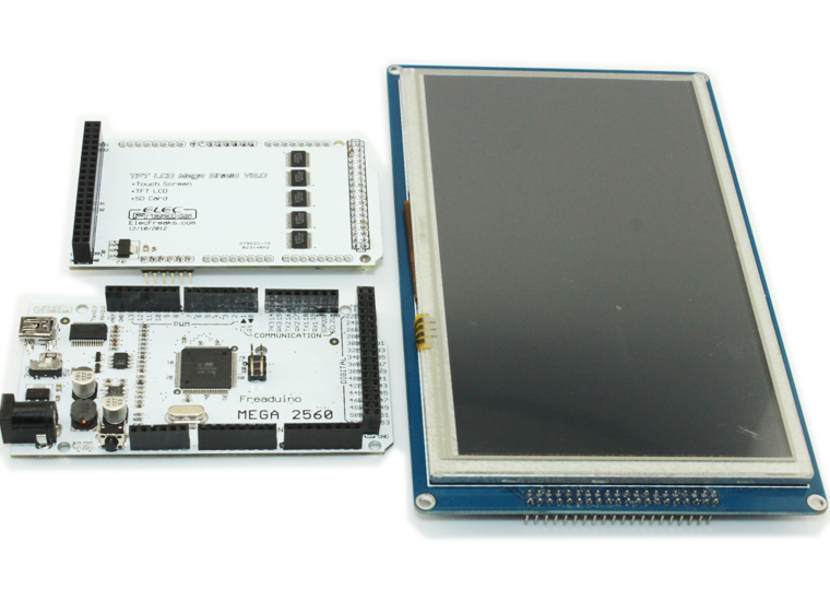
What do we need?
- As a basis, I used Frearduino ADK v.2.2 based on the ATmega2560 processor
- TFT LCD Mega Shield v.2.2
- The display itself - 7 "TFT LCD SSD1963 ( Here you will find its description, as well as the necessary documentation )
- UTFT Library - a universal library for working with TFT displays (You can find the library itself, as well as documentation, here )
- Soldering iron
')
Understand the iron
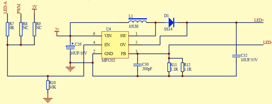
When you open the display, you can see that the mp3032 converter has three inputs: LED-A, PWM, 5V. Initially, PWM is inactive. This entry is not used at all. The backlight is controlled by LED-A.
If you look at the back of the display, you can find an area that is
"Backlight control" . Here we will find these same inputs. To control the backlight by the PWM method, it is necessary to make it all the other way around: LED-A is inactive, PWM is active. To do this, you have to rewire the jumper. Here is a photo of what should happen: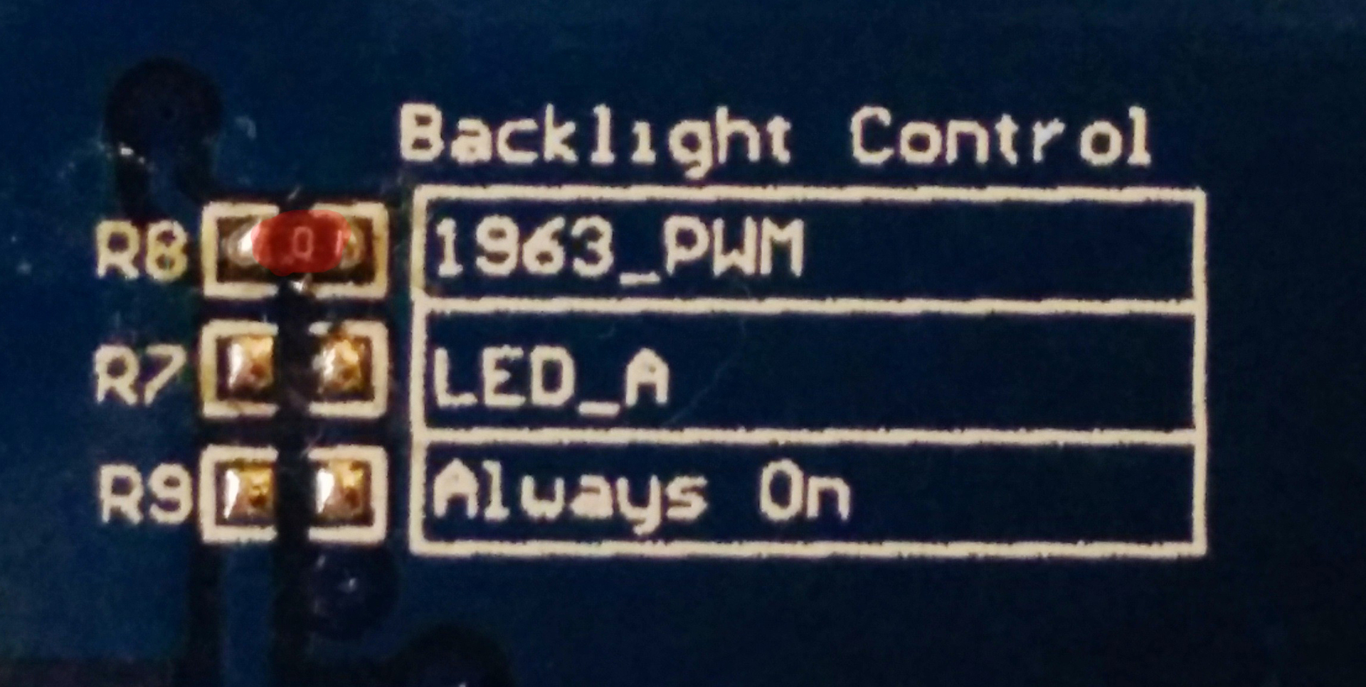
Software part
Since our library cannot provide what we need, we ourselves will write the necessary function. To do this, open the documentation for the controller that controls the display (SSD1963). SSD1963 is controlled using special commands that are transmitted from the Arduino via special outputs, which are described in the documentation:
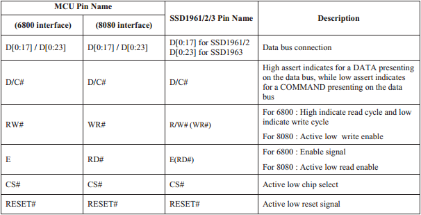
The control is as follows: Arduino outputs via RS (D / C in the table) 0, if we are going to send a command, 1 - if the data. After sending the command, the RS switches to 1, and then the necessary parameters are transmitted. All commands and parameters are transmitted through the outputs D0-D7. If you have an ATmega2560, then all these eight outputs are combined into port C.
So, for starters, let's write the data transfer function on the bus. For ease of use, I will write directly to UTFT.h:
void Lcd_Writ_Bus(uint8_t bla) { digitalWrite(WR,LOW); // SSD1963 digitalWrite(CS, LOW); PORTC = bla; // digitalWrite(CS,HIGH); digitalWrite(WR,HIGH); } You should also pay attention to the names of the methods, since functions with the same names can already be found in the library.
Add two functions for outputting commands and data:
void Lcd_Write_Com(uint8_t data) { digitalWrite(RS,LOW); // RS , 0 Lcd_Writ_Bus(data); } void Lcd_Write_Data(uint8_t data) { digitalWrite(RS,HIGH); // RS , 1 Lcd_Writ_Bus(data); } Now the setting itself backlight. To find out how to do all this, open the documentation and look for a command to configure PWM.
Note:
PWM can be controlled, with the help of DBC - a dynamic brightness control system, but I, for simplicity, did not use it. You, if you want, can find the necessary information in the same documentation.So, here's what we need:
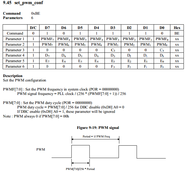
That is, we must first send the “0xBE” command, and then, as the 3 parameters, pass the signal frequency, the duty cycle duration, and the third parameter, which determines whether the DBC is on or not (0x01 - off, 0x09 - on) .
To adjust the brightness itself, you only need to change the frequency of the operating cycle. Since we transmit data in the form of one byte, the values of the cycle can be from 0 to 255. I decided to define 9 levels of brightness (from 0 to 8). Therefore, all 256 values need to be broken down into 9 steps. But you should also pay attention to the fact that if the steps are equal, then the brightness will not change as smoothly as we would like. That is, for example, at the 4th stage, the brightness will be almost maximum, and from the 4th to the 8th stage will change almost imperceptibly. Given this, I decided to use a geometric progression with a denominator of 2. That is, the brightness will be calculated using the following formula:
(2 ^ lvl) - 1 , where lvl is the brightness level from 0 to 8. Note that since the values start from zero, then you need to subtract the unit. Of course, you can choose the steps and their values yourself, but I gave this, quite simple example. Now the code itself: void setBright(byte lvl) { byte brightness(1); for (byte i(1); i <= lvl; i++) // brightness *= 2; Lcd_Write_Com(0xBE); // Lcd_Write_Data(0x01); // 760 Lcd_Write_Data(brightness-1); // Lcd_Write_Data(0x01); // DBC } Now you can use
UTFT.setBright(byte lvl);Source: https://habr.com/ru/post/234601/
All Articles