Personal cloud on Raspberry Pi and development of uninterruptible power supply for it

Idea
For several years I used services like Dropbox and Yandex Disk, I decided that I had to make my own storage. I chose between X86 server on Windows / Ubuntu, Raspberry Pi, Odroid, CubieBoard and others. I stopped at Raspberry Pi, because it is the cheapest solution and already fully written instructions for it - and I'm new to Linux, the presence of step-by-step manuals is important to me.
From the side of the software I chose between OwnCloud and BittorentSync. I tried both and chose the second - I liked the decentralization and the ability to store data in an unreliable place encrypted (more on that later). I also wanted to solder something of my own, and I decided to make an uninterruptible power supply on a lead-acid battery.
It was supposed that Pi would be an always-on device, in the meantime BittorentSync would still work on the work computer and home, a small part of the data is also synchronized with the phone. As a result, information should be stored in three places: one of them is always on, computers are encrypted by Truecrypt, and on Pi data is encrypted using BittorentSync.
Configure BittorentSync
How to configure it and connect a hard disk to Pi, I will not describe . I only tell about a feature that I have not found in any of these tutorials. As you know, the sharing occurs by copying the key (secret in BittorentSync terminology). There are keys Read only and Read write. But there is another encrypted secret . If you share this key, the machine will be able to download the data, but each file will be encrypted with the key obtained from this encrypted secret. The problem is that this third type of keys cannot be generated in the usual way, you must first ask for the API key from them , then pomamanit with config files, and then the web server on 127.0.0.1 will generate three types of key at once.
')
Circuit design
I can draw a diode bridge, but this article is still partially about me. In developing the scheme, I relied on thorough modeling of all processes and did not consider anything, as taught in the institutes, I twisted everything in the simulator in order not to be mistaken. I read dozens of articles with battery chargers and UPS circuits and surprisingly found that most of them simply do not work, my simulation of these circuits shows that they are wrong. At the same time in the comments they write "thanks, everything is ok." It seems that no one checked them. In the end, I checked them all and collected a mutant of a dozen schemes, which seemed to work in the simulator ...
Electrical circuit
For convenience, the whole scheme is divided into 3 parts: UPS with battery, automatic shutdown circuit, exit.
Part 1
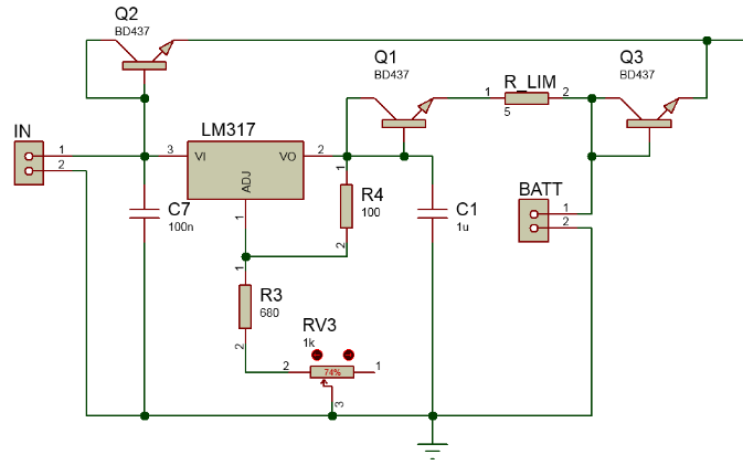
Here, on the left, the input voltage is supplied from the notebook power supply to 19V, the operating range is 16-30V. The voltage regulator LM317 has an output of 13.6V. Why 13.6? - that's why .
Resistors R4, R3, RV3 are tuned to make 13.6V. It was possible to accurately calculate the resistance and do without a trimming resistor, but I decided not to count it exactly, but just then tweak it.
Capacitors C1 and C7 serve to filter the power on the LM317. In principle, it was possible to do without them, because the output of the notebook adapter has its own filters, and the battery is not sensitive to voltage peaks for charging. But I decided to leave them as recommended by datasheets.
The R_LIM resistor is needed to limit the current through the LM317 and through the battery, without it the LM317 will overheat.
Three BD437 diodes are needed so that the high voltage of the power supply unit is not poured into the battery and that the battery does not attempt to charge itself through the LM317. Although I deceived, these are not diodes, but transistors, in which the base is closed to a collector - that is, they function as diodes. What is the best diode? When choosing components, I proceeded from those that are available in the store and for which there is a model in the simulation program. It turned out that the smallest voltage drop under load of these parts is such a transistor, and not a diode, even Schottky. To minimize the voltage drop you need to increase efficiency. If, for example, the voltage drop across the diode is 1V, and a current of 0.5A flows through it, then we throw away nothing in the air half a minute per second.
Part 2

Lead-acid batteries have the following peculiarity: if you continue to suck energy out of them when it is almost over, their service life drops. Therefore, when the battery voltage drops to 12.2, the load must be turned off. This circuit is a comparator that compares the battery voltage with some reference voltage, and decides when to cut off the load current.
The scheme works as follows. The battery voltage is applied to the Zener diode 11.5V and to the input of the reference voltage source AD680. Resistors R6, R5, RV2 form a voltage divider, such that it is close to the battery voltage minus the Zener diode voltage (11.5V). A comparator outputs 0V if its negative input is larger, and> 12V if positive more. The resistor with RV2 twist is adjusted so that this shutdown happens just as the power drops below 12.2V. A pull-up resistor R9 is needed for normal operation of the LM393 comparator, as it is written in datasheet. Capacitors C5 and C4 are needed to filter out these sensitive analog signals in front of the comparator.
Everything would be fine, but when I modeled this scheme, the following problem appeared. Under load, the voltage sags a little. When it falls below 12.2V, the load is disconnected and the sagging disappears. As a result, the voltage rises slightly. This is enough for it to go back beyond the threshold of operation, and the circuit turns on the load again. From this the voltage sags again, and the circuit turns it off. A terrible thing happens: in the vicinity of the threshold, the load is switched on and off at high speed, nobody will like this.
To solve this trouble was added resistor RV1. He adds hysteresis to this comparator. The point is that it adds a bit of voltage to the input when the output is positive. After disconnecting the load, this “help” also disappears, and the voltage must increase more in order to return. Imagine that in one direction you need to step over the curb, and back you can roll on the sloping without a curb.
Part 3

It's simple. The power output for the load, filter capacitors, the main transistor-key and of course the LED. A device without LED - money down the drain.
Job modeling

There are 3 graphics on these pictures:
- change in battery voltage, given by a sinusoid from 12 to 12.6V
- 2 lines of voltage at the input of the comparator (red flat reference voltage, green - output after the Zener diode and divider)
- current through load (on or off)
It is seen that when the voltage drops to 12.2V, the transistor closes, and the current through the load ceases to flow. Then, after increasing the voltage by more than 12.3V (this difference can be adjusted by a twist-resistor), the transistor opens again, thereby forming a hysteresis. The time scale in these graphs does not matter, it was necessary only to test at what voltages on-off occurs.
Printed circuit board
This simple fee can be collected on the knee, but I wanted to get the experience of ordering a beautiful board from the factory. Another solution would be to find a friend of the Jedi laser irons, but did not. He quickly found a company in China that agreed to make me a batch of 5 pieces for $ 10 + $ 4 shipping. “Good price” - I thought and ordered. After that, for the sake of interest, sent a request to one popular Zelenograd office, they announced a price of 3,500 rubles. “Thank you for the offer,” I thought. The Chinese worked quickly, they already sent it in 2 days, in 2 weeks the mail delivered.
It was - it became

It was

It became

then an inquisitive eye will notice that instead of a single microchip, a device on 3 legs is I didn’t inadvertently check the packaging of the device upon purchase. Also, again due to carelessness, I didn’t check the diameter of the holes, and I had to fix the board like that in a curve on the side of the bolts. Right on the photo is the DC-DC converter on the XL4015 microcircuit . I chose it instead of the most popular LM2596 due to its high efficiency and maximum power. It is also clear that there are two of them in 3 places instead of the usual resistor. This is because I did not have a suitable denomination and had to fence such a “the beast with two backs”.
Testing
From the first time, of course, did not work. It turned out that in CAD the standard pinout of legs for a trimmer resistor does not coincide with the real one. I had to rewire them. Then it didn't work due to the fact that the Zener diode had too much voltage and crushed the signal, and I rewired it with another 1 volt less.
And now, the hysteresis in my comparator, it works! When you turn off the power from the outlet, the Raspberry Pi continues to work and distributes BittorentSync! In every way she tortured her, pulled out of the socket, pulled the contacts, the board worked stably and did not hang.
I decided to look at transitional processes using an oscilloscope.
Here is the power on and off without load (Raspberry Pi is not connected)


The green line is the output of the DC-DC converter, it should be 5V. Yellow line - 19V powered from notebook adapter. It can be seen that there are no fluctuations when turning off, and when turning on a small peak.
Here is the power on and off with the load (the Raspberry Pi and the hard disk are connected and working)


Switching off as usual is good, and when turned on, a peak of 740mV appears. In theory, this is not scary, Pi and the disk have their own filter capacitors, they will survive 5V + 740mV for 300µs.
It is recommended to connect power to Pi not via USB, but through GPIO connectors 1 and 3. Then the power goes around the self-resetting fuse, otherwise there will not be enough current to the hard disk.
Pi has a known problem of rebooting and hard drive failure. This problem is treated by soldering an additional 200-300 uF capacitor over the existing USB capacitor. Here is an article explaining how. I did not do this, because it already worked.
Price
Raspberry Pi - 1600r
Printed circuit boards 10 + 4 $
Components for board 500r
USB hard drive - already been
DC-DC Converter - $ 4.75
Voltage indicators - $ 8
Battery 12V, 4.5 Ah - 480r
Case - 250 r
Total approximately 3800r
Disadvantages and future development
When the boards arrived, I discovered several jambs. Basically - not the best arrangement of elements. In CAD, it seemed that everything was perfect, and when I took them in hand, I realized that the capacitors could be moved there, that circuit could be turned like this, etc. Next time I will print the scheme to touch hands before production.
The LM317 chip should be replaced with a DC-DC converter, for example, LM2596, for greater efficiency and higher charge current.
The values of all capacitors could be adjusted to reduce the peak at power up.
Now plans to connect to the Pi relay and turn on the light bulb through the web server, but I will not write about this article.
That's all.

Source: https://habr.com/ru/post/234211/
All Articles