Google Project Tango: disassembling the "spatial tablet" from iFixit (4 out of 10 on the repair scale)
On Habré, several times they mentioned the new Google Project Tango tablet, which is able to rebuild the 3D model of the room in which the tablet is located. This device is not yet widely available, and every second user is unlikely to be interested in them, the device’s features are too specific.
Nevertheless, the device can be in demand among architects, graphic designers, civil engineers and representatives of a large number of other specialties. The other day, the iFixit service team disassembled the tablet, and assessed its maintainability.
')
Before looking at what happened as a result, it is worth remembering what the tablet is, its characteristics.
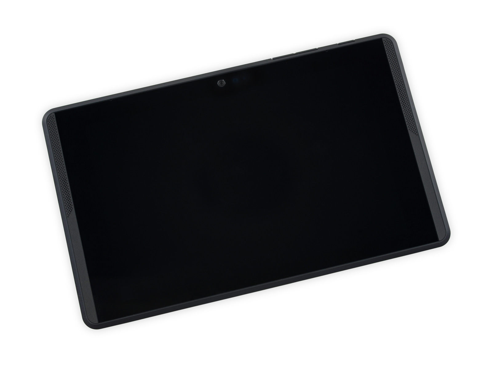
And this is a 7-inch touchscreen display (resolution 1920x1080), NVIDIA Tegra K1 processor with a frequency of 2.3 GHz, 128 GB of internal memory, 4 GB of RAM, two cameras with a viewing angle of 120 and 170 degrees (front and rear cameras, respectively). There are also infrared sensors - motion sensors, responsible for building a model of the room in which the tablet is located.
Step 1
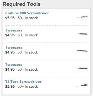
Actually, the tablet itself, the preparation of tools. Tools used in the disassembly process:
Step 2

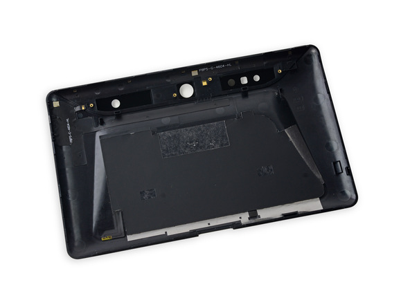
Removing stickers, which are quite a lot. Under the stickers buried model number: NX-74751.
Step 3

A little more inspection: the connector in the tablet is non-standard, it supports 12V fast charging. There is USB 3.0

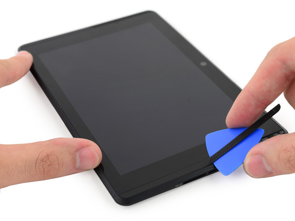
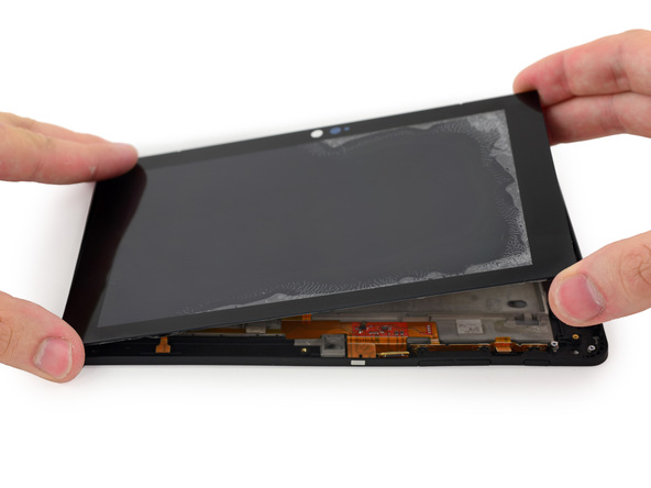
Step 4

No screws, no special fasteners: the case opens quite simply and painlessly.

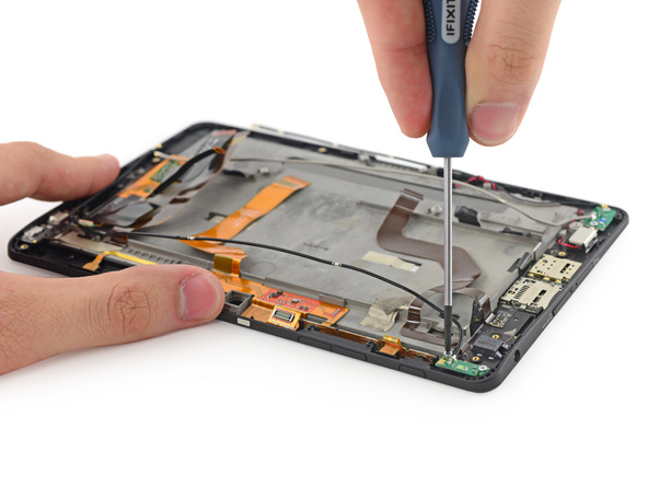
Step 5

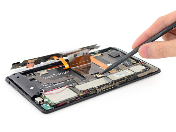
A bit of work with a screwdriver near the camera, and the camera board is released from captivity.
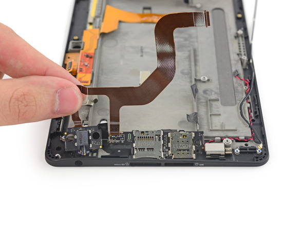
Step 6
Disconnecting the control camera board.

Step 7
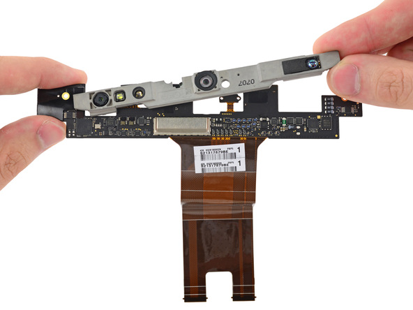

Several integrated circuits on the camera control board: STM32L151QD , PCA9546A , LT3743 , NCP45560 .
Step 8
Access to infrared emitter / projector Mantis Vision


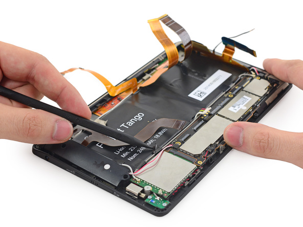
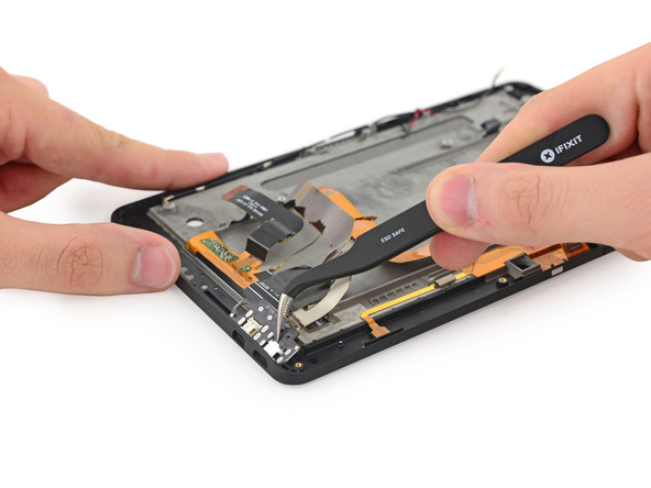
Step 9
The battery is not easy to disconnect. The adhesive is moderate.
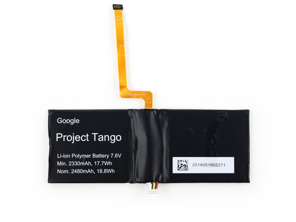
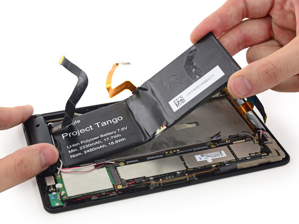
Step 10
And here is the battery. It was designed specifically for this tablet.
Step 11
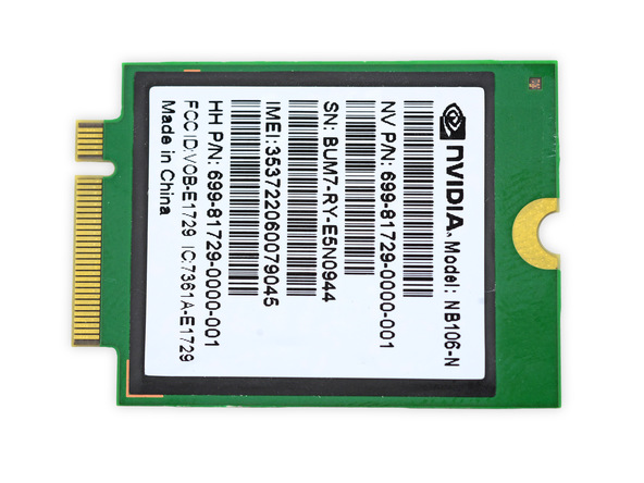
The module is a baseband signal transmission.
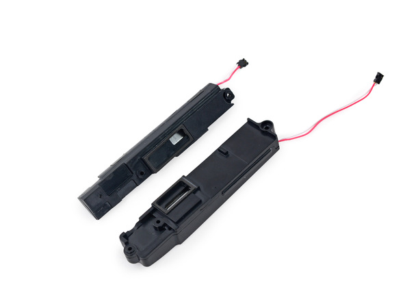
Step 12
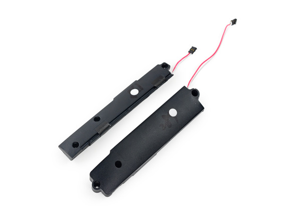
The audio system of the tablet with multiple microphones and speakers.

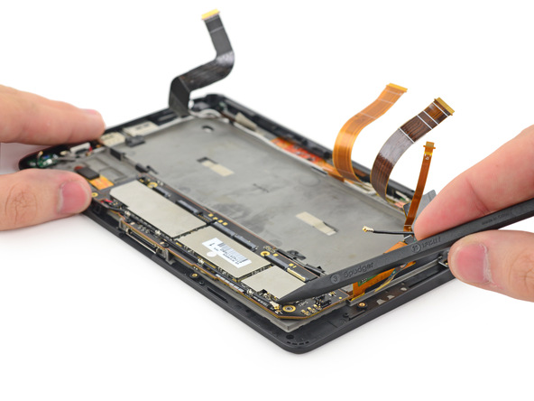
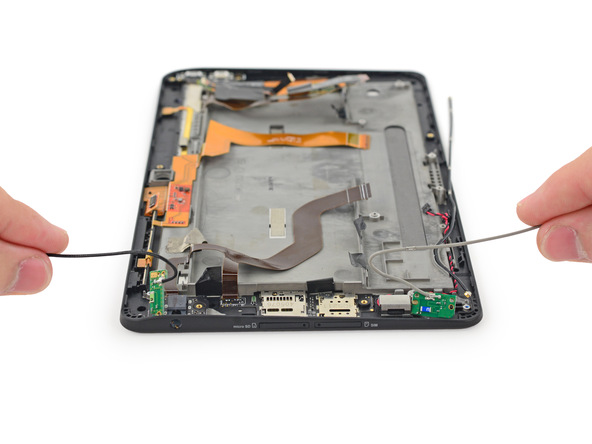
Step 13
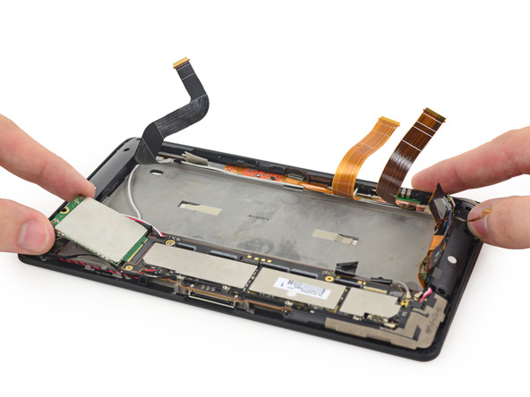
The release of the motherboard. Here we see two antenna cables.

Step 14

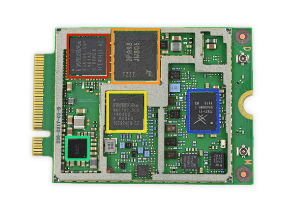
Main elements:
- Red: Nvidia TD580D-A1 2.3 GHz quad-core Tegra K1;
- Orange: SanDisk 4133DF4PG02X 128 GB memory;
- Yellow: Elpida RAM FA232A2MA 2 GB;
- Green: Broadcom BCM4752IUB2G GNSS receiver;
- Blue: Broadcom BCM43341XKUBG wireless module;
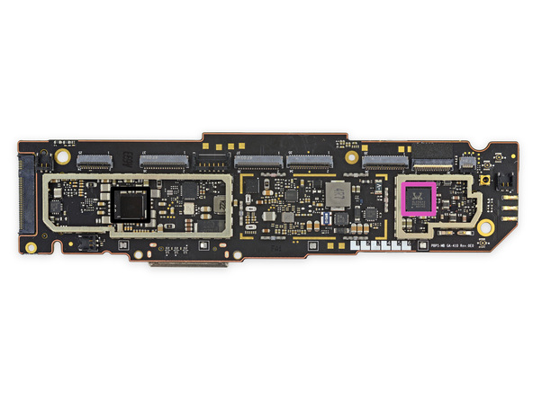
- Audio chip Realtek ACL5642 Hi-Fi;
- Texas Instruments 45A2RFI;
Step 15
Antennas and cameras:
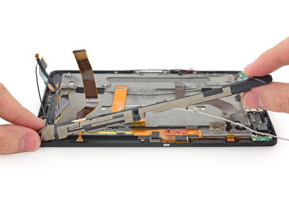

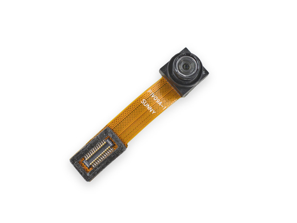
Step 16
More antennas!

Step 17
Some adhesive on the headphone jack, memory card slot and SIM. It all separates:

Step 18

Step 19
Separate the display controller for the display - RM31280 50051 1418A1U0.
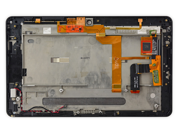
Step 20

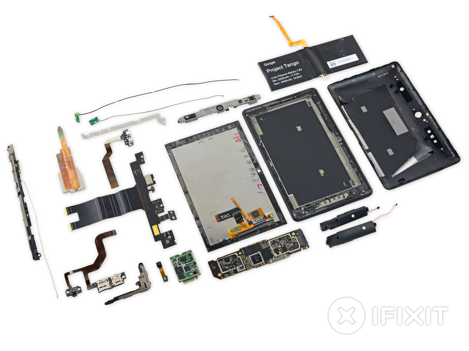
Step 21
All elements of the tablet, the end of the disassembly process.
Via ifixit
Source: https://habr.com/ru/post/234023/
All Articles