Led romb
It was evening, there was nothing. (with)
It was about 3 years ago. I stumbled upon one video LED cube 8x8x8 demo and to be honest, it impressed me. At that time my hands for a long time were itching to create something like that. Then I did not know what an Arduino was, and indeed I had a vague idea even how to connect a LED correctly. Gaining courage, I went to the Internet, where I quickly found ideas and schemes for how to assemble such cubes, and a store where you can buy components. I chose a 4x4x4 cube as the best option for the first experience.
')
A bit of theory and thinking:
How to light a LED?
Energize and connect ground. Power 5V - need a resistor.
How to light 16 diodes with the ability to light separately?
Need 16 keys to supply voltage.
How to light any diode from a 4x4x4 matrix?
We put the matrix on the "floors" 4 by 4. We get 16 keys for voltage on the "pillars" + 4 for opening the ground on the "floor".
Total need 20 controlled outputs of a certain microcontroller.
I didn't dare to solder the strapping and program the microcontroller from scratch without experience and chose the Arduino, or rather the Freeduino analogue.
Freeduino nano v5
Microcontroller: ATmega328
Digital I / O ports: 14 ports (6 of them with PWM signal)
Analog input ports: 8 ports
22 programmable inputs / outputs with a voltage of + 5V with a logical unit - what you need.
Materials:
LEDs 64pcs.
Resistors 20 pcs.
Bipolar transistors 4 pcs.
MK: Freeduino Nano v5
Wiring, switch, connectors, layouts and more.
The LEDs and Freeduino were purchased at the nearest store; the rest is evaporated from the nearest power supply or found elsewhere.
So, we proceed:
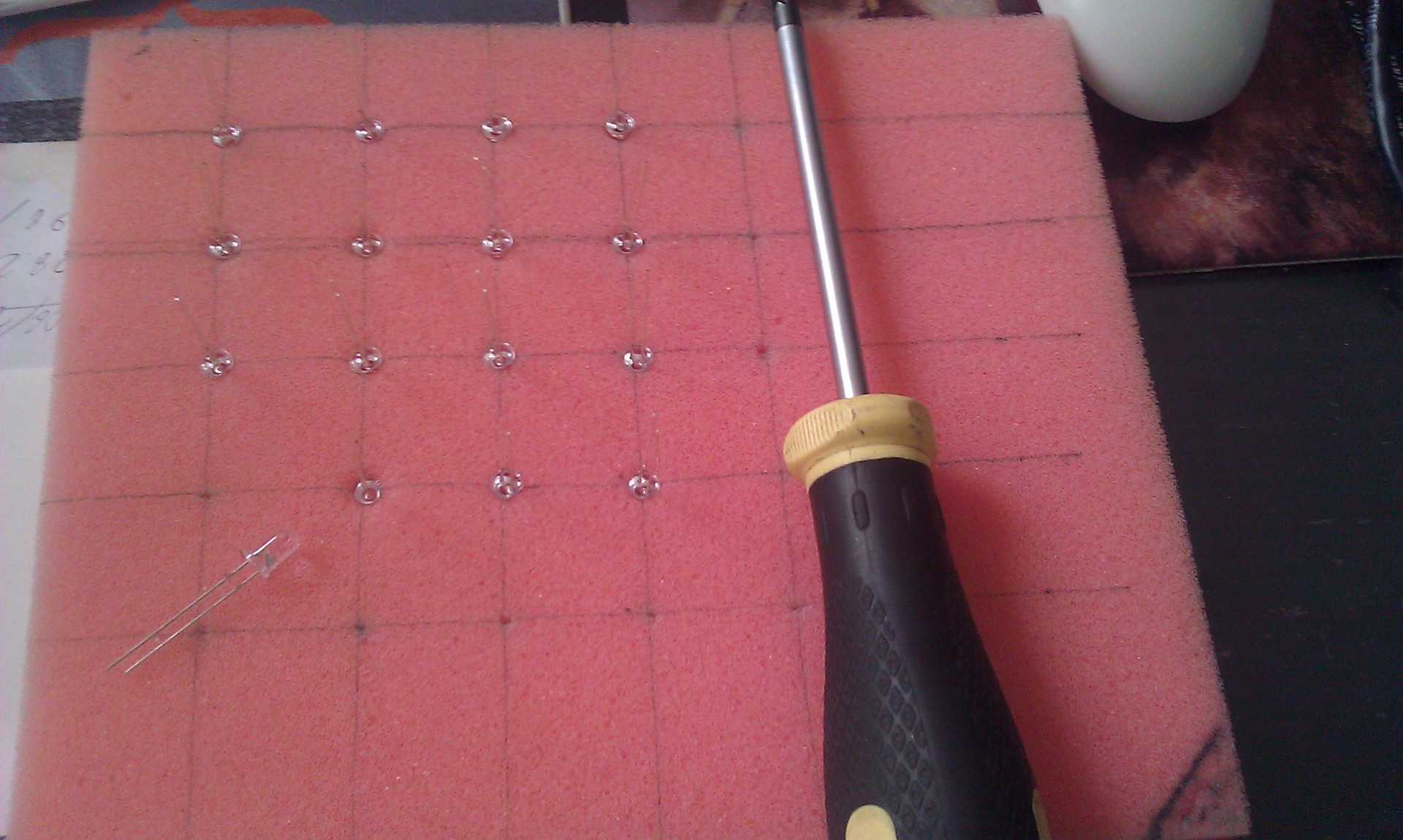
We mark something on squares with sides of 5 mm by 5 mm - this is the length of the short of the LED legs.
Bend the cathode at 90 degrees - we will solder them in a chain, getting the "floors" and beautifully set on the previously obtained matrix template.
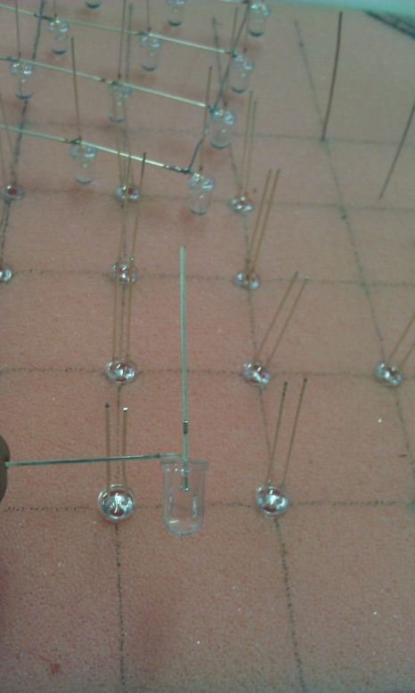
Next, bend the anode (long leg) at a slight angle. This is required so that it is convenient to solder the "floors"
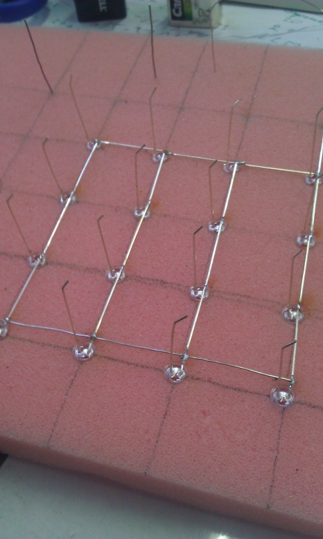

and solder everything together.
It's time to test.
Since the LEDs were blue, found a blue loop and dismissed it.
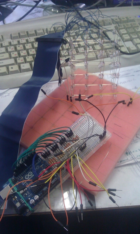
When it all worked on the layout joy there was no chapel.
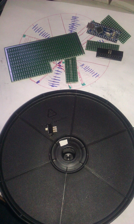
We collect a pedestal.
It just so happened that I bought exactly 64 LEDs and one was lost. I did not have a store where I could buy it on the way, and it was quite strange to order delivery due to one diode. The exit was found by itself - to put a cube on a truncated face! And the original and appearance only wins. A box of blanks just fit in size. In it for reliability and the possibility of disconnection, the switch floats over the ground.
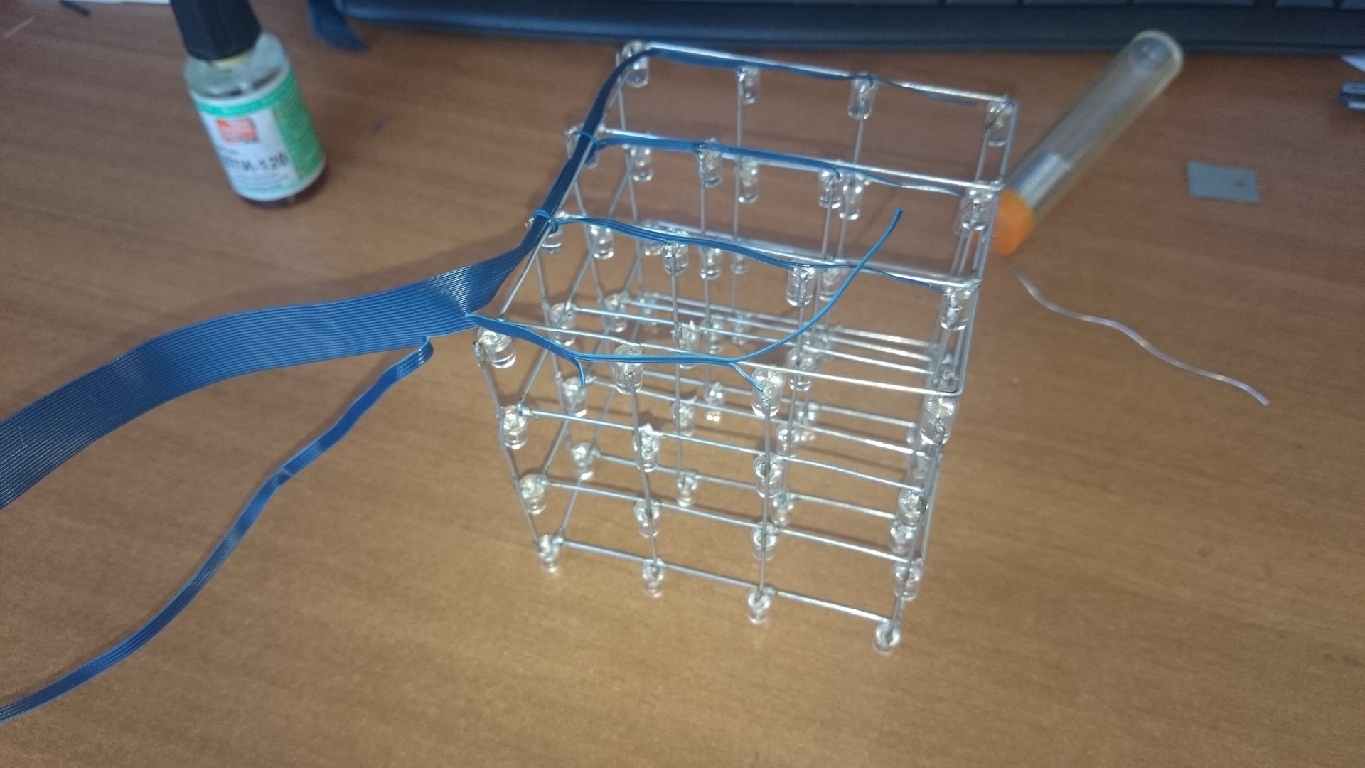
Next are the photos of the updated version. The first assembled cube fell victim to a local scale cataclysm and was irretrievably lost except for the base. To collect the updated version, I did not bend the legs anymore, because they are very soft and poorly shaped, I cut them almost to the root, and made connections from steel wire 0.9 mm from the hardware store. Fuss turned out more, but the result is much better. Smoother edges, and the stiffness of the structure has increased. Diodes are already taken from the Chinese and collected a full 4x4x4 cube.
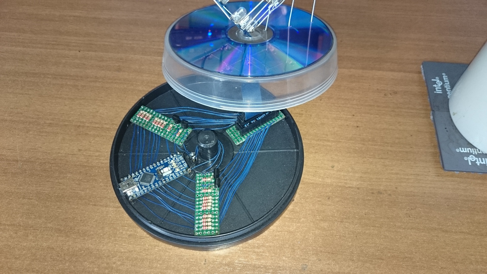
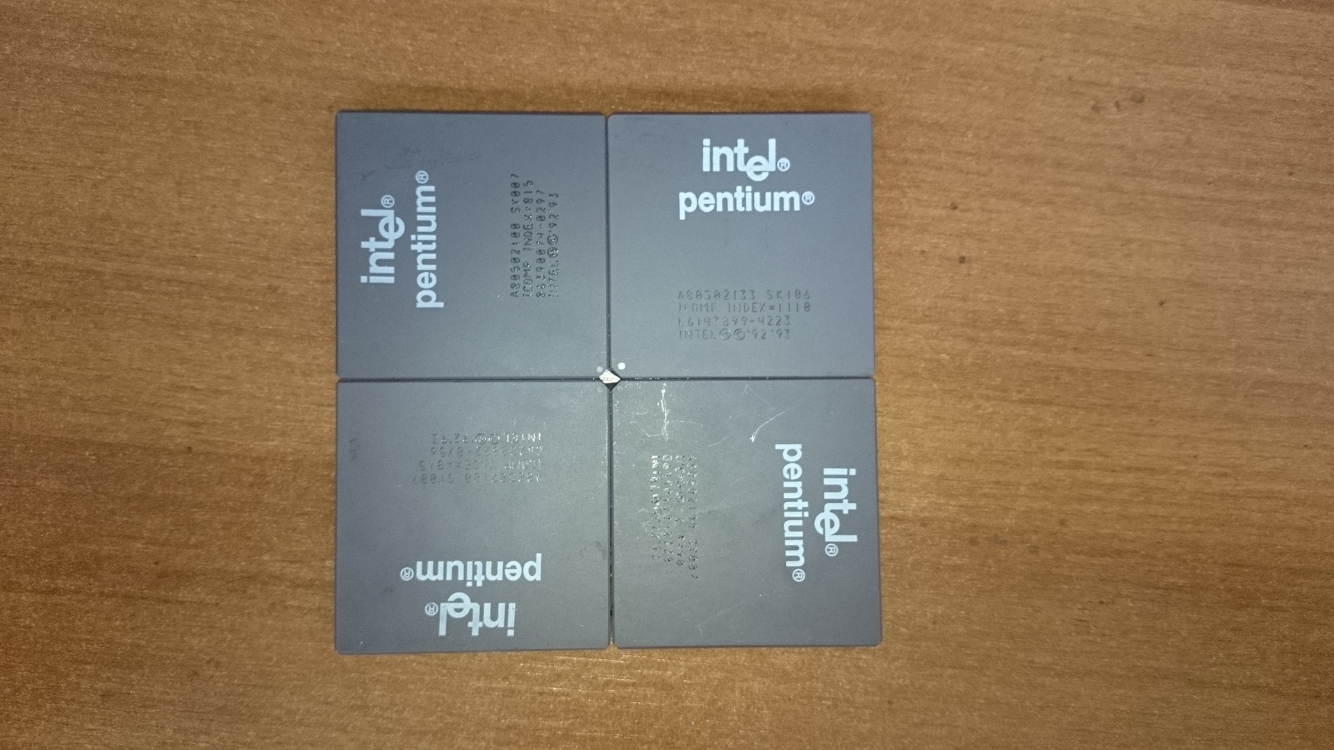
What is inside:
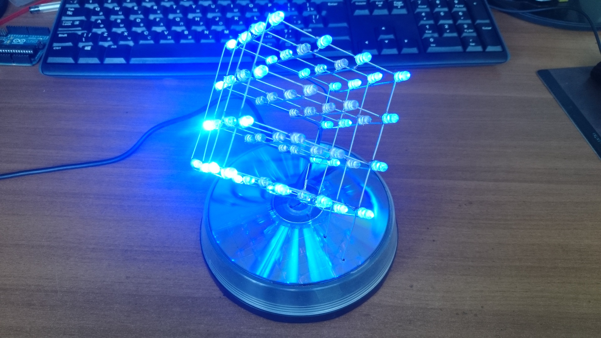
And the result:
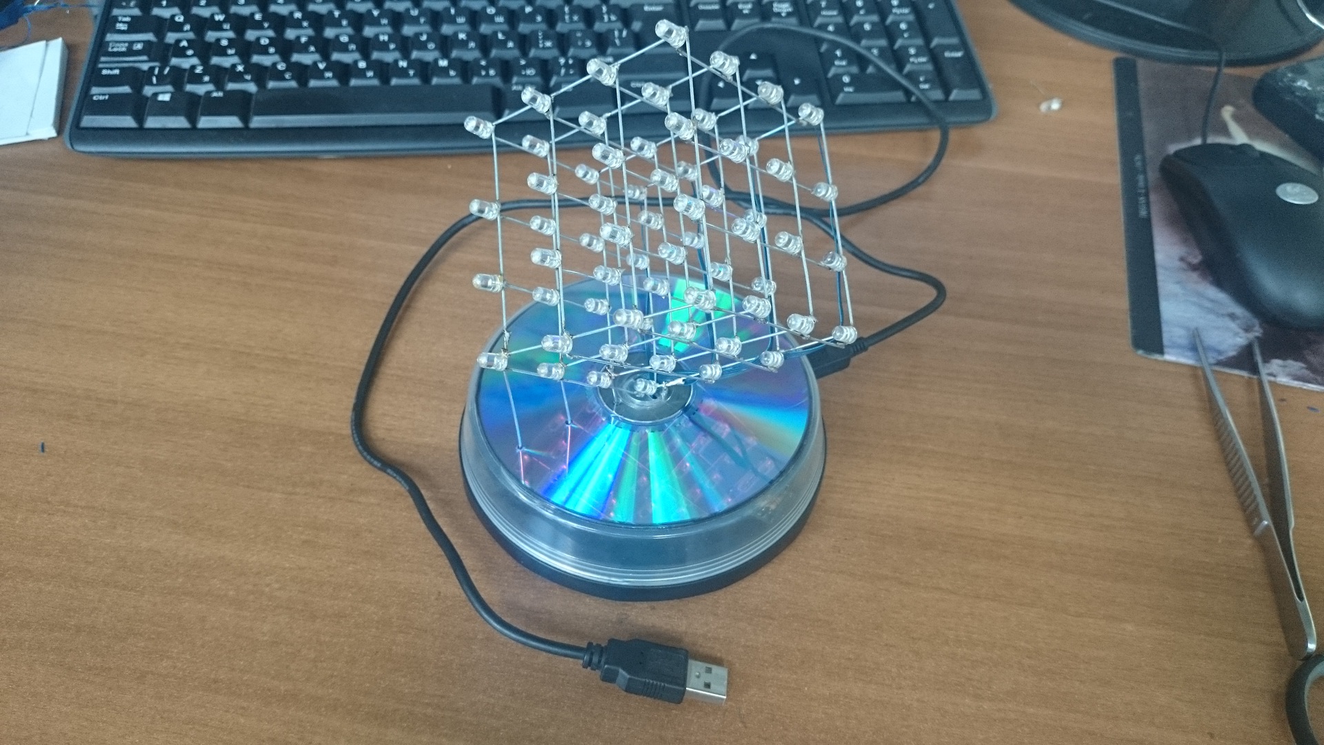
Powered by any source at 5V. Most often connected to a USB port. For programming, you must turn off the cube, so as not to glow. because Outputs 0 and 1 were used, which are also used for programming the controller. When the illumination is turned on and the program works, current flows through the outputs, which leads to failures in 90% of cases when a new sketch is cast.
I didn't write about the Arduino IDE. Simple cycles are nothing interesting and there are already a lot of examples on the Internet.
If someone has an interest, add the code and make a video.
Led romb
Thanks for attention.
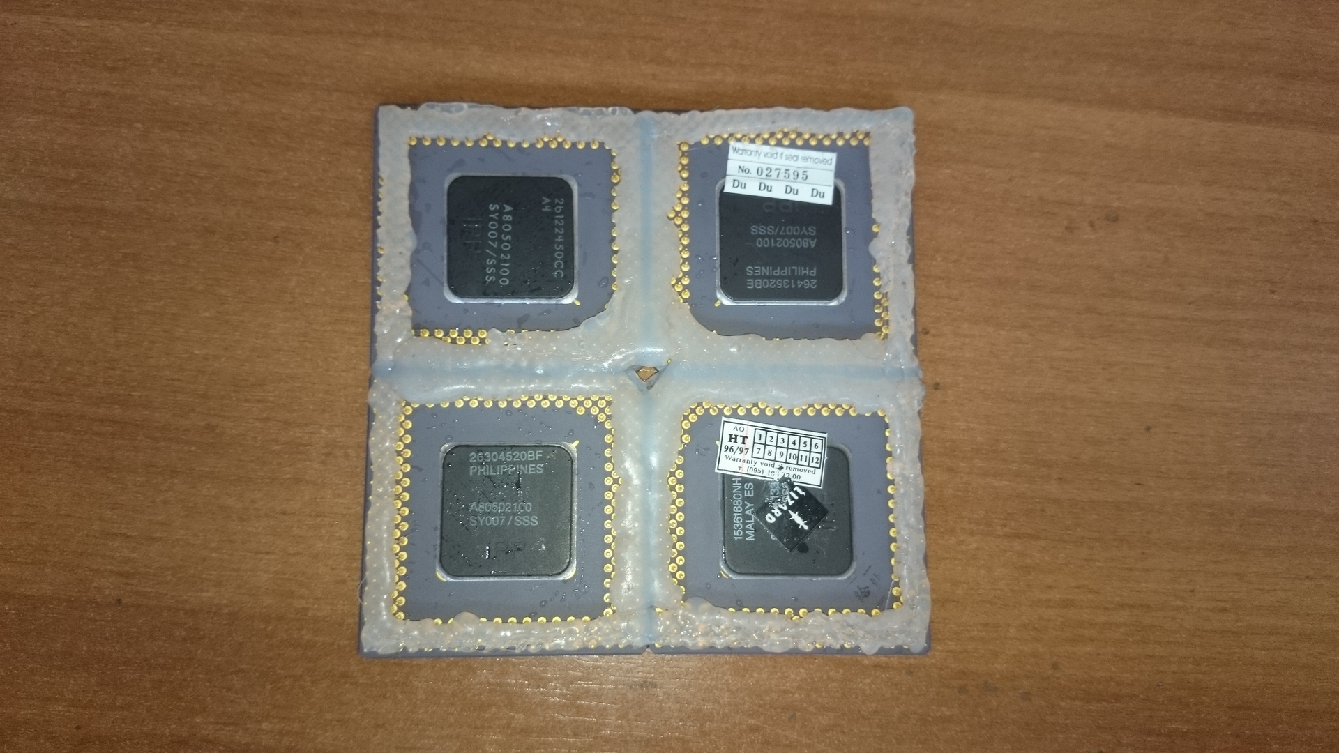
ZY Revising before publishing the article saw the edge of the stand under the circles. I feel there will be questions "what's under the mug?".
Here is:
Glued with glue gun.
It was about 3 years ago. I stumbled upon one video LED cube 8x8x8 demo and to be honest, it impressed me. At that time my hands for a long time were itching to create something like that. Then I did not know what an Arduino was, and indeed I had a vague idea even how to connect a LED correctly. Gaining courage, I went to the Internet, where I quickly found ideas and schemes for how to assemble such cubes, and a store where you can buy components. I chose a 4x4x4 cube as the best option for the first experience.
')
A bit of theory and thinking:
How to light a LED?
Energize and connect ground. Power 5V - need a resistor.
How to light 16 diodes with the ability to light separately?
Need 16 keys to supply voltage.
How to light any diode from a 4x4x4 matrix?
We put the matrix on the "floors" 4 by 4. We get 16 keys for voltage on the "pillars" + 4 for opening the ground on the "floor".
Total need 20 controlled outputs of a certain microcontroller.
I didn't dare to solder the strapping and program the microcontroller from scratch without experience and chose the Arduino, or rather the Freeduino analogue.
Freeduino nano v5
Microcontroller: ATmega328
Digital I / O ports: 14 ports (6 of them with PWM signal)
Analog input ports: 8 ports
22 programmable inputs / outputs with a voltage of + 5V with a logical unit - what you need.
Materials:
LEDs 64pcs.
Resistors 20 pcs.
Bipolar transistors 4 pcs.
MK: Freeduino Nano v5
Wiring, switch, connectors, layouts and more.
The LEDs and Freeduino were purchased at the nearest store; the rest is evaporated from the nearest power supply or found elsewhere.
So, we proceed:
We mark something on squares with sides of 5 mm by 5 mm - this is the length of the short of the LED legs.
Bend the cathode at 90 degrees - we will solder them in a chain, getting the "floors" and beautifully set on the previously obtained matrix template.
Next, bend the anode (long leg) at a slight angle. This is required so that it is convenient to solder the "floors"
and solder everything together.
It's time to test.
Since the LEDs were blue, found a blue loop and dismissed it.
When it all worked on the layout joy there was no chapel.
We collect a pedestal.
It just so happened that I bought exactly 64 LEDs and one was lost. I did not have a store where I could buy it on the way, and it was quite strange to order delivery due to one diode. The exit was found by itself - to put a cube on a truncated face! And the original and appearance only wins. A box of blanks just fit in size. In it for reliability and the possibility of disconnection, the switch floats over the ground.
Next are the photos of the updated version. The first assembled cube fell victim to a local scale cataclysm and was irretrievably lost except for the base. To collect the updated version, I did not bend the legs anymore, because they are very soft and poorly shaped, I cut them almost to the root, and made connections from steel wire 0.9 mm from the hardware store. Fuss turned out more, but the result is much better. Smoother edges, and the stiffness of the structure has increased. Diodes are already taken from the Chinese and collected a full 4x4x4 cube.
What is inside:
And the result:
Powered by any source at 5V. Most often connected to a USB port. For programming, you must turn off the cube, so as not to glow. because Outputs 0 and 1 were used, which are also used for programming the controller. When the illumination is turned on and the program works, current flows through the outputs, which leads to failures in 90% of cases when a new sketch is cast.
I didn't write about the Arduino IDE. Simple cycles are nothing interesting and there are already a lot of examples on the Internet.
Sketch Rhombus
/* Rombik Arduino. Created by Azurius */ int i,z,x,c,v,b,a,s,d; int dt = 100; int dts = 2; int nprog =1; int tmp1=0, tmp2=0, tmp3=0; int timeb=0, timew=0; int LEDM[4][4] = { 4,5,6,7, 8,9,10,11, 16,17,18,19, 15,14,12,13}; int LEDF[4] = { 3,2,0,1}; int ma[12]={ 4,5,6,7,11,19,13,12,14,15,16,8}; int mas[4]={ 0,3,12,15}; void setup() { for (i=0;i<4;i++){ for (z=0;z<4;z++){ pinMode(LEDM[i][z], OUTPUT); } } for (i=0;i<4;i++){ pinMode(LEDF[i], OUTPUT); } LedOFFAll(); //tushim vse pered nachalom } void LedON(int pin){ digitalWrite(pin, HIGH); } void LedOFF(int pin){ digitalWrite(pin, LOW); } void DotON(int kx, int ky, int kz){ LedON(LEDM[kx][ky]); LedON(LEDF[kz]); } void DotOFF(int kx,int ky, int kz){ LedOFF(LEDM[kx][ky]); LedOFF(LEDF[kz]); } void LedOFFAll(){ for (i=0;i<4;i++){ for (z=0;z<4;z++){ LedOFF(LEDM[i][z]); } LedOFF(LEDF[i]); } } void change(){ timew=millis(); if ((timew-timeb)>=10000){nprog++;timeb=millis();dt=70;} if (nprog==10) nprog=1; } void loop() { change(); //nprog = 0; //##########[## Prog 0 ############## // ALL ON if (nprog==0){ // ON begin for (c=0;c<4;c++){ LedON(LEDF[c]); for (i=0;i<4;i++){ for (z=0;z<4;z++){ LedON(LEDM[i][z]); delay(300); LedOFF(LEDM[i][z]); } } LedOFF(LEDF[c]); } } // end nprog 0 //############ Prog 1 ############## // zajigaet po ocheredi tochkami if (nprog==1){ // ON begin for (c=0;c<4;c++){ for (i=0;i<4;i++){ for (z=0;z<4;z++){ DotON(i,z,c); delay(dt); DotOFF(i,z,c); } } } } // end nprog 1 //############ Prog 2 ############## // zajigaem stolbiki po ocheredi if (nprog==2){ // ON begin for (c=0;c<4;c++){ LedON(LEDF[c]); } for (i=0;i<4;i++){ for (z=0;z<4;z++){ LedON(LEDM[i][z]); delay(dt); } } for (i=0;i<4;i++){ for (z=0;z<4;z++){ delay(dt); LedOFF(LEDM[i][z]); } } } // end nprog 2 //############ Prog 3 ############## // zajigaem etaji po ocheredi if (nprog==3) { // ON begin for (i=0;i<4;i++){ for (z=0;z<4;z++){ //LedON(LEDF[c]); LedON(LEDM[i][z]); } } for (c=0;c<4;c++){ LedON(LEDF[c]); delay(dt); LedOFF(LEDF[c]); } LedOFFAll(); } //end nprog 3 //############ Prog 4 ############## // Zmeyka po granyam if (nprog ==4){ dt=30; while(1){ x=v; v=random(0,3); if(x!=v){break;} } if(v==0){if(i==0){ for(b=0;b<4;b++){i=b;DotON(i,z,c); delay(dt); DotOFF(i,z,c);}} else{ for(b=3;b>-1;b--){i=b;DotON(i,z,c); delay(dt); DotOFF(i,z,c);}} } if(v==1){if(z==0){ for(b=0;b<4;b++){z=b;DotON(i,z,c); delay(dt); DotOFF(i,z,c);}} else{ for(b=3;b>-1;b--){z=b;DotON(i,z,c); delay(dt); DotOFF(i,z,c);}} } if(v==2){if(c==0){ for(b=0;b<4;b++){c=b;DotON(i,z,c); delay(dt); DotOFF(i,z,c);}} else{ for(b=3;b>-1;b--){c=b;DotON(i,z,c); delay(dt); DotOFF(i,z,c);}} } } //end nprog 4 //############ Prog 5 ############## // goryashie grani if (nprog == 5){ for (c=0;c<4;c++){ LedON(LEDF[c]); for (i=0;i<12;i++){ LedON(ma[i]); if (c==1 | c==2){ i=i+2; } } delay(dts); LedOFF(LEDF[c]); for (i=0;i<12;i++){ LedOFF(ma[i]); } } }// end nprog 5 //############ 6 ########### // ploskosti po ocheredi if (nprog==6){ // ON begin for (i=0;i<4;i++){ LedON(LEDM[i][0]); LedON(LEDM[i][3]); LedON(LEDF[i]); } delay(1000); LedOFFAll(); for (i=0;i<4;i++){ LedON(LEDM[0][i]); LedON(LEDM[3][i]); LedON(LEDF[i]); } delay(1000); LedOFFAll(); } //end nprog 6 //############ 7 ########### if (nprog==7){ i=random(0,4); z=random(0,4); c=random(0,4); DotON(i,z,c); delay(dt); DotOFF(i,z,c); } //end nprog 7 //############ 8 ########### if (nprog==8){ //random up i=random(0,4); z=random(0,4); v=random(0,4); b=random(0,4); a=random(0,4); s=random(0,4); LedON(LEDM[i][z]); LedON(LEDM[v][b]); LedON(LEDM[a][s]); for (c=0;c<4;c++){ LedON(LEDF[c]); delay(dt); LedOFF(LEDF[c]); } LedOFF(LEDM[i][z]); LedOFF(LEDM[v][b]); LedOFF(LEDM[a][s]); } //end nprog 8 //############ 8 ########### if (nprog==9){ //obhod po krugu LedOFFAll(); for(c=0;c<4;c++){ LedON(LEDF[c]); } for(i=0;i<12;i++){ LedON(ma[i]); delay(dt); if(i>1){LedOFF(ma[i-2]);} } } //end nprog 9 } // end loop Led romb
Thanks for attention.
ZY Revising before publishing the article saw the edge of the stand under the circles. I feel there will be questions "what's under the mug?".
Here is:
Glued with glue gun.
Source: https://habr.com/ru/post/234019/
All Articles