LED "smiley". Technology multiplexing method "Charlie"
Hello to all!
I want to tell the story of the emergence of a single device, by the example of which I began to learn how to work with electronics. Perhaps it will be interesting to those who also want to join the community of electronics developers, but do not know where to start.
')
Under the cut, I tried to talk about what I did, how I did it, and what I want to do next.
Once upon a time I ordered an Arduino controller from ebay.com for a long time that I was lying on my desk for a long time. At that time I was not engaged in electronics and I did not dare to begin my acquaintance with it. And then came the moment when I decided to test the Arduino. By this time I read a lot of forums and “first steps” on using this controller, so I was not so afraid to burn something when building the first scheme (I did not have any ready-made arduino shields yet).
At the beginning, like all beginners, he blinked LEDs, connected a couple of buttons, tried to light up the LEDs by clicking on them. But I wanted to move and develop further. I looked on the Internet for various devices that are collected using this controller - “licked”. I didn’t want to buy something, basically I stopped the delivery of purchases from abroad, because it was only possible to buy something interesting.
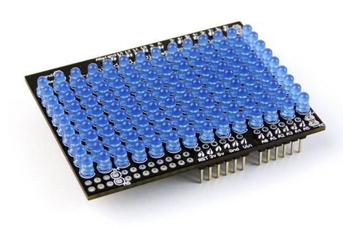
I especially liked the Arduino LOL-shield. I started to read more about him and looked at the diagram.
By this time, in my baggage of knowledge and skills, the Arduino Single Side board was independently manufactured using LUT technology. The most interesting thing is that she earned it right after the assembly, and I still don’t understand a huge number of people who collected the same board in the same way and in the comments to the article on its assembly and launch complained that they had it does not work.
In a word, I decided to make the same shield myself.
After studying the LOL shield scheme, it turned out that it works on the basis of the Charliplexing method. If you search the Internet, then there is a sufficiently large amount of information about what this method is and how it can be used. I will try to talk about him in a few words.
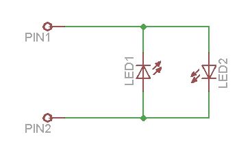
In the classic version, plus the LED (via a load resistor) is connected to the digital output of the Arduino, and the minus - to the ground. Connection diagram is shown below:

With this connection to the digital contacts of the controller (14 pins) you can connect a total of 14 LEDs. You can use other schemes to turn on LEDs, for example, using shift registers and then the number of LEDs can be easily increased.
The method of Charliplexing allows you to connect up to N * (N-1) LEDs on the N pins of the microcontroller. That is, if we have 2 microcontroller pins, then we can connect 2 LEDs, if 3 outputs, then there are already 6 LEDs, 4 to 12 LEDs, etc.
LEDs will turn on the following:
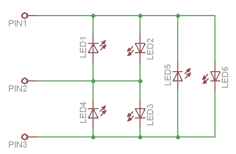
From these diagrams one can see how the LEDs turn on and how, by adding the affected contacts, the number of connected LEDs increases.
The engineer Charlie Allen came up with this scheme in 1995. The scheme is based on 3 states of the microcontroller pins: 5V (HIGH), 0V (LOW) and INPUT state. When the microcontroller leg is in the INPUT state, since the pull-up resistor is turned on, it seems to be completely disconnected from the circuit and the current does not flow through it. It is possible to reduce the possible states of all LEDs for a circuit with six LEDs in the table:
That is, in order to light up the LED LED1, it is necessary to set the states indicated in the table for this LED to the outputs of the Pin1, Pin2, Pin3 microcontroller.
The program in the Arduino IDE environment in order to light the LED1 LED will look as follows (the circuit is connected to the Arduino 11, 12, 13 digital outputs):
After downloading this program to the microcontroller and starting it, the LED1 in the circuit should light up.
A small note to the circuit: I have no current-limiting resistors on the LEDs on the circuit. They are needed, since the current through the LEDs flows the same as with their classical connection. But since two legs of the controller are involved to turn on the LED, instead of a 100 Ohm resistor on the plus leg of the LED, I put 50 Ohm resistors on each leg of the controller. Maybe this is not entirely correct, but at least for me with this scheme, the LEDs have been working for quite a long time, until none of them failed.
It is clear from the table above and the example given that at the same time only one LED can be lit at this time. In order to ensure the simultaneous operation of several LEDs, fast switching of operating LEDs in the circuit is used. The human eye does not have time to see this switch and it seems that at the same time several LEDs are lit.
I will give an example of how to simultaneously "light up" all the LEDs in the circuit of 6 LEDs.
Six LEDs seemed to me a little. Still, initially I wanted to make LOL-shield. Alas, my dream of self-assembly of the LOL-shield at home did not come true - it was simply impossible to dissolve a one-sided board with so many LEDs. Having looked at the original board from the manufacturer, I saw that there is a double-sided board, and to minimize the via holes, they are realized right in the places where the LEDs are soldered. At home, the metallization of vias is a very difficult task.
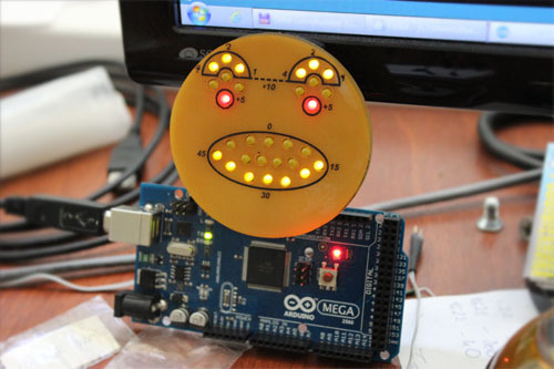
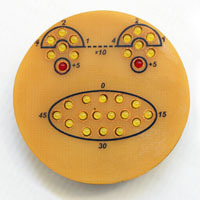
After that, I had an idea (not mine of course, I saw it somewhere on the Internet) to make a small icon in the form of an emoticon, the expression of which can be changed. This badge can be attached to your jacket and go with it to a party, well, or just wear it as a funny keychain.
I drew a scheme in EagleCAD and spread it there. Unfortunately, the scheme does not shine with special beauty - it was one of my first schemes that I developed on my own. There turned out a bunch of jumpers. Its main advantage is that it is one-sided and without metallized vias. However, the scheme is quite working.
She looked like this after production:

In order to somehow improve the appearance of the circuit, namely to close the jumpers on the front side, I made an overlay of fiberglass laminate with holes for the LEDs.
As a last step, I wrote a sketch for the Arduino, which would draw different emoticons.
Download the scheme and the diluted fee, as well as a sketch with the program here .
In my sketch, different types of emoticons are set using a hexadecimal code. Each time I felt lazy to consider this code, so I wrote an additional program in Delphi, where you can visually mark those LEDs that need to be lit in a smiley and the program itself generates a smiley code. The program interface looks like this:
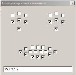
The source code of the program in Delphi and the program itself for generating emoticons can be found here .
While I was writing and debugging a program for an emoticon, I began to think about how to make the second part of the scheme. You will not walk with the Arduino board and the emoticon board stuck in there at a party or wear it as such as a keychain. At the stage of debugging the sketch, I just connected to the Arduino board and lay on the table.
What happened next, I will try to tell in the next part of the article.
I want to tell the story of the emergence of a single device, by the example of which I began to learn how to work with electronics. Perhaps it will be interesting to those who also want to join the community of electronics developers, but do not know where to start.
')
Under the cut, I tried to talk about what I did, how I did it, and what I want to do next.
Once upon a time I ordered an Arduino controller from ebay.com for a long time that I was lying on my desk for a long time. At that time I was not engaged in electronics and I did not dare to begin my acquaintance with it. And then came the moment when I decided to test the Arduino. By this time I read a lot of forums and “first steps” on using this controller, so I was not so afraid to burn something when building the first scheme (I did not have any ready-made arduino shields yet).
At the beginning, like all beginners, he blinked LEDs, connected a couple of buttons, tried to light up the LEDs by clicking on them. But I wanted to move and develop further. I looked on the Internet for various devices that are collected using this controller - “licked”. I didn’t want to buy something, basically I stopped the delivery of purchases from abroad, because it was only possible to buy something interesting.
I especially liked the Arduino LOL-shield. I started to read more about him and looked at the diagram.
By this time, in my baggage of knowledge and skills, the Arduino Single Side board was independently manufactured using LUT technology. The most interesting thing is that she earned it right after the assembly, and I still don’t understand a huge number of people who collected the same board in the same way and in the comments to the article on its assembly and launch complained that they had it does not work.
In a word, I decided to make the same shield myself.
Charlie multiplexing
After studying the LOL shield scheme, it turned out that it works on the basis of the Charliplexing method. If you search the Internet, then there is a sufficiently large amount of information about what this method is and how it can be used. I will try to talk about him in a few words.
In the classic version, plus the LED (via a load resistor) is connected to the digital output of the Arduino, and the minus - to the ground. Connection diagram is shown below:
With this connection to the digital contacts of the controller (14 pins) you can connect a total of 14 LEDs. You can use other schemes to turn on LEDs, for example, using shift registers and then the number of LEDs can be easily increased.
The method of Charliplexing allows you to connect up to N * (N-1) LEDs on the N pins of the microcontroller. That is, if we have 2 microcontroller pins, then we can connect 2 LEDs, if 3 outputs, then there are already 6 LEDs, 4 to 12 LEDs, etc.
LEDs will turn on the following:
From these diagrams one can see how the LEDs turn on and how, by adding the affected contacts, the number of connected LEDs increases.
The engineer Charlie Allen came up with this scheme in 1995. The scheme is based on 3 states of the microcontroller pins: 5V (HIGH), 0V (LOW) and INPUT state. When the microcontroller leg is in the INPUT state, since the pull-up resistor is turned on, it seems to be completely disconnected from the circuit and the current does not flow through it. It is possible to reduce the possible states of all LEDs for a circuit with six LEDs in the table:
| Light-emitting diode | Pin1 | Pin2 | Pin3 |
| LED1 | LOW | HIGH | INPUT |
| LED2 | HIGH | LOW | INPUT |
| LED3 | INPUT | HIGH | LOW |
| LED4 | INPUT | LOW | HIGH |
| LED5 | LOW | INPUT | HIGH |
| LED6 | HIGH | INPUT | LOW |
That is, in order to light up the LED LED1, it is necessary to set the states indicated in the table for this LED to the outputs of the Pin1, Pin2, Pin3 microcontroller.
The program in the Arduino IDE environment in order to light the LED1 LED will look as follows (the circuit is connected to the Arduino 11, 12, 13 digital outputs):
Scratch text for Arduino IDE
int pin1 = 11; int pin2 = 12; int pin3 = 13; void setup() { pinMode(pin1,INPUT); // " " pinMode(pin2,INPUT); pinMode(pin3,INPUT); pinMode(pin1,OUTPUT); // pinMode(pin2,OUTPUT); digitalWrite(pin2,HIGH); // } void loop() { } After downloading this program to the microcontroller and starting it, the LED1 in the circuit should light up.
A small note to the circuit: I have no current-limiting resistors on the LEDs on the circuit. They are needed, since the current through the LEDs flows the same as with their classical connection. But since two legs of the controller are involved to turn on the LED, instead of a 100 Ohm resistor on the plus leg of the LED, I put 50 Ohm resistors on each leg of the controller. Maybe this is not entirely correct, but at least for me with this scheme, the LEDs have been working for quite a long time, until none of them failed.
It is clear from the table above and the example given that at the same time only one LED can be lit at this time. In order to ensure the simultaneous operation of several LEDs, fast switching of operating LEDs in the circuit is used. The human eye does not have time to see this switch and it seems that at the same time several LEDs are lit.
I will give an example of how to simultaneously "light up" all the LEDs in the circuit of 6 LEDs.
Scratch text for Arduino IDE
#define n 3 // int pin[n]={11,12,13}; int i,j; void setup() { // INPUT for (byte i=0;i<n;i++) { pinMode(pin[i],INPUT); digitalWrite(pin[i],LOW); } } void loop() { for (i=0;i<n;i++) { // PIN , // pinMode(pin[i],OUTPUT); for (j=0;j<n;j++) { if (i==j) { continue; } pinMode(pin[j],OUTPUT); digitalWrite(pin[j],HIGH); delayMicroseconds(300); digitalWrite(pin[j],LOW); pinMode(pin[j],INPUT); } pinMode(pin[i],INPUT); } } Six LEDs seemed to me a little. Still, initially I wanted to make LOL-shield. Alas, my dream of self-assembly of the LOL-shield at home did not come true - it was simply impossible to dissolve a one-sided board with so many LEDs. Having looked at the original board from the manufacturer, I saw that there is a double-sided board, and to minimize the via holes, they are realized right in the places where the LEDs are soldered. At home, the metallization of vias is a very difficult task.
After that, I had an idea (not mine of course, I saw it somewhere on the Internet) to make a small icon in the form of an emoticon, the expression of which can be changed. This badge can be attached to your jacket and go with it to a party, well, or just wear it as a funny keychain.
I drew a scheme in EagleCAD and spread it there. Unfortunately, the scheme does not shine with special beauty - it was one of my first schemes that I developed on my own. There turned out a bunch of jumpers. Its main advantage is that it is one-sided and without metallized vias. However, the scheme is quite working.
She looked like this after production:
In order to somehow improve the appearance of the circuit, namely to close the jumpers on the front side, I made an overlay of fiberglass laminate with holes for the LEDs.
As a last step, I wrote a sketch for the Arduino, which would draw different emoticons.
Download the scheme and the diluted fee, as well as a sketch with the program here .
In my sketch, different types of emoticons are set using a hexadecimal code. Each time I felt lazy to consider this code, so I wrote an additional program in Delphi, where you can visually mark those LEDs that need to be lit in a smiley and the program itself generates a smiley code. The program interface looks like this:
The source code of the program in Delphi and the program itself for generating emoticons can be found here .
While I was writing and debugging a program for an emoticon, I began to think about how to make the second part of the scheme. You will not walk with the Arduino board and the emoticon board stuck in there at a party or wear it as such as a keychain. At the stage of debugging the sketch, I just connected to the Arduino board and lay on the table.
What happened next, I will try to tell in the next part of the article.
Source: https://habr.com/ru/post/233465/
All Articles