I still love graphics programming.
About a year ago I wrote a story about one of my bikes, which I called “ I love graphics programming ”. In that story, I tried to show the development process “from the romantic side”, a little poshutiv over myself, they say everything is so fun and funny when you program graphics. I told the story only from “Wow! Polosatenko ... ”, and now, almost a year later, I decided to share with you a story about how it all worked and how it ended. I want to immediately warn you that this is still a story about bicycles. This is not a story about revolutionary technologies or super-mega smart solutions. This is a story about how I, at my own pleasure, intentionally wrote a bicycle.
The story again is a little confused and everyone who doesn’t like Android, C ++, Live Wallpaper, Minecraft, bicycles, a stream of consciousness that is loosely tied to the topic and everything, I want to immediately warn you that they can be upset by the content of this post, so keep reading at one's own risk.
')
Past story?
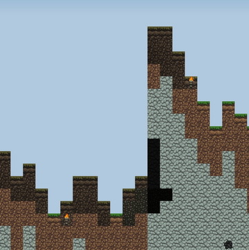
For those who do not know and do not want to read the previous article, I will tell you briefly what it was about. I wrote Live Wallpaper for Android, in the style of Minecraft. In fact, just a picture of the landscape in the style of the game Minecraft, which you can flip through with your finger and in which there is a change of day and night.
Little about bikes
In the past, my story I made a digression to talk about the game, which I wrote many years ago because of nostalgic feelings, and in this story I decided not to differ in particular originality and to start with the same.
In 2006, I was the happy owner of the CCP. The VGA screen and all the other buns of this device provided quite ample opportunities and at that time I wrote several applications for Windows Mobile.
One of the applications that I wrote was a game that in my childhood was called “Egg Killer” and which spent a lot of childhood time and children's nerves. Without going into details, I took a set of images from the emulator and made a game based on them:
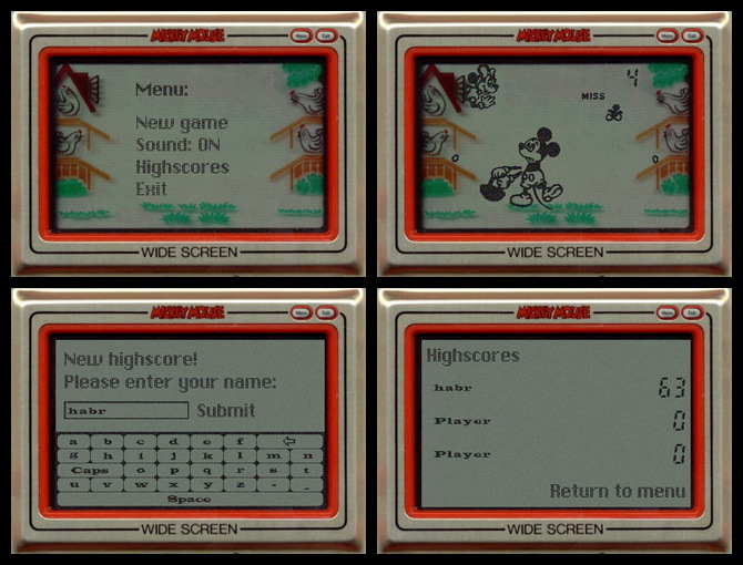
But I am not telling this in order to advertise the PDA and not only from nostalgic feelings. This is a story about bicycles - about bicycles that are created intentionally.
At that time, I had enough experience in software development to write such a simple game in less than a day. As I said before, the Rafik and the soundtrack were taken from the emulator, the logic is simple to the point, and the output to the screen of 10 sprites certainly did not make any problems. Perhaps the fact that the implementation was too simple was for me the main problem. After all, I decided to write this game for myself - not for sale, not for someone, but just for myself, which means I have to get something more than a ready-made game from it. The process was supposed to be fun.
Here bicycles came to the rescue ... Its image format, for sprites that should be displayed on the screen (on top of the background image). Its process of displaying these sprites with the effect of white noise. And everything was implemented through FrameBuffer, i.e. through an array of pixels. And now the task has already taken about 4 days and has become much more interesting.
I will quote myself from the previous article:
I wrote it, it worked exactly as I remembered, I played it once, I quit it, because already “played up” in the process of debugging.But for me it has become a kind of tradition ...
You see, every year on December 31, my friends and I go to the bathhouse. This is our tradition.I began to realize things from time to time, for myself, so that, as they say, “stretch the brain”. And this process gives me a lot of pleasure, so I immediately want to give an answer to those who like to scream in the comments: “Phe-poo-pooh, why so ?! Yes, you need perlin noise and fractal generation of areas! ”. - Yes, for everything that I describe in this story, I have my own methods and my own tools - I know that very well. My implementation has nothing to do with the fact that I do not know about the existence of ready-made solutions. The essence is in the implementation of their decisions.
Back to the topic
It was written a simple application Live wallpaper, which simply painted over the screen in a certain color. I will not tell you how to do this, because This is the part that can be easily found in search engines. In the application, the “draw” method was responsible for drawing, which did something like the following:

Here began the first problems with performance ...
SDK Features
Initially, the question was how to get an image from JNI and the most logical solution seemed to get an array of int, which would represent a bitmap with a 32-bit pixel representation (32bpp). This approach was also driven by the fact that Java offers a method for outputting such an array on canvas:

I proceeded from this logic - an array of pixels can be obtained from a Bitmap object, but it will definitely be longer than just transferring an array and drawing an array using a method that was specially made for that.
Here I was in for a surprise from Android: the drawBitmap method was drawing a picture (720x1280) for about 21ms, so if I want to draw 30 frames per second (even if without delays - taking up the entire processor), then my implementation would have to fit in 12ms (and Yes, here I do not even take into account the fact that drawing itself is not the only thing that takes time). This arrangement certainly did not suit me, so I had to experiment and look for other options. The solution was to transfer the Bitmap object to JNI, which in the drawing method was processed as follows:
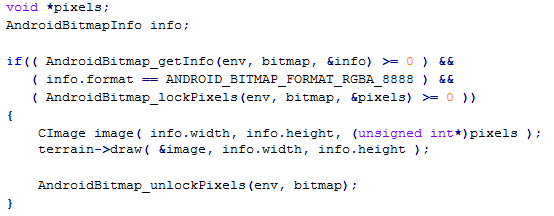
So, transferring an object like Bitmap, getting information about it (AndroidBitmap_getInfo), getting an array of pixels (AndroidBitmap_lockPixels / AndroidBitmap_unlockPixels) and the actual JNI call itself (without my drawing), now took no more than 1ms. At this stage, the problem of transferring the image to JNI and back has been resolved. I didn't find anything in the documentation about why using the drawBitmap method with an array of pixels works so long, but it can be assumed that in that case, just before drawing, a Bitmap object is created.
Overhead costs somehow remained because receiving and releasing a Canvas object with each drawing takes approximately 1-2 ms. And the Bitmap output itself using the drawBitmap method takes another 3-4m:

In total, about 5-6ms have to be given for additional operations, but then I could not do anything and had to accept.
This is probably the only interesting technical aspect that was encountered in Java, so the further narrative goes to JNI and to the implementation of the landscape generation algorithms.
Skyline and cyclical
The landscape itself was displayed cyclically, i.e. the image is a closed ribbon that can be scrolled endlessly in any direction (horizontally). From the point of view of the algorithm, it is possible to generate a landscape of any length, but the length is limited so as not to consume too much memory.
From the point of view of implementation, everything is very simple here:
If it is necessary to generate a region whose points extend beyond the map (horizontally), then these points are simply transferred to the other side of the map (for x <0, x + = width and for x> = width, x - = width). The question of the implementation of the horizon level is a bit more interesting - the horizon should be random, but the start and end points should converge so that there is no such effect:
To solve the problem, the following algorithm was written:
- Randomly choose y coordinate of the starting point.
- The next point can have one of the offsets relative to the previous point: {-2, -1, 0, 1, 2}, for each of the offsets it is checked whether it is possible to return to the starting point for the remaining number of transitions. The offset, the choice of which does not allow to go to the starting point, is removed from the list.
- A random offset value is selected from the list.
- Repeat from the second point, until you come to the beginning.
In practice, this approach allows us to generate both flat surfaces of the landscape and “mountains”. To tell the truth, I know that the algorithm is the most optimal and that it should have been based on the distortions of the straight line, but at that time, the solution seemed sufficient.
Caves and other elements
One of the main tasks was the generation of caves, and various blocks (coal, sand, etc.). There are quite a few algorithms for solving this problem, but I decided to write everything myself, as it comes to my mind.
The implementation was similar to the implementation of the flood fill algorithm, only with some element of randomness:
- Select a random point, set the “weight” for this point (random number).
- Check the availability of neighboring points (process each of the neighboring points, reducing the “weight” randomly) - whether the point is outside the screen, if the point was not processed previously.
The “weight” of neighboring points is determined by a random number ranging from (“weight” of the parent point / 2) to the “weight” of the parent point. Additionally, the ability to create more random regions was added to the generation algorithm by adding the “extra randomness” condition, where the child points are not considered with 20% probability.
The process of traversing points is quite clearly possible to show with the help of animation:

A bit different animation, which shows the process of reducing the "weight" from the center:

At its core, the algorithm is recursive, but a queue was used for implementation. The starting point is added to the processing queue and the loop is executed as long as there are points in the queue. Available adjacent points with a weight greater than 0 are added to the queue. In general, everything is pretty standard, in terms of solving the problem of excessive depth of the call stack.
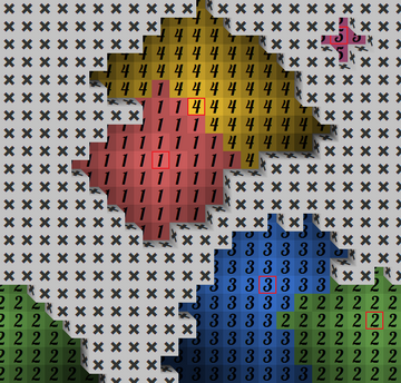
This algorithm is performed in several passes - it creates several initial points from which the child points are processed. As a result, the regions are randomly interconnected, creating more complex regions. Here is an example of creating five regions (the points of each region are marked with numbers from one to five, the starting point of the region has a red frame):
This algorithm is the basis for most of the landscape, only the number of starting points (the points from which separate regions are created), the starting “weight” for the starting points, and the position of the starting points (this is done so that certain regions are created only within a certain depths, for example, only near the bottom).
The starting points of the regions were also used to place lighting elements (torches). In the earlier version, the torches were located at the initial points of the region, but then I decided to lower them “to the ground” and if the initial point of the region is higher than in two blocks from the “floor”, then the torch was placed exactly in two blocks from the floor. This approach made the lighting more interesting (large parts of the region could remain dimly lit).
Again about performance
The whole development process I struggled with performance. It was necessary to alter quite a lot, when at the testing stage it became clear that the drawing required too much time. I did not invent anything particularly original, I implemented only the process of identifying changed areas, so that only the area that really needs to be redrawn was involved in the drawing. The rest was taken from the past image. So, for example, when turning over, the most part remained unchanged, and only the segment that needed to be added was drawn (in the image, the blocks that need to be drawn are marked in red):

The algorithm was responsible not only for the offset, but also for the area, the lighting of which changed with the change of time:
Pseudo 3d
“Pseudo-oboe” was also created quite simply - the position of the block is always fixed - in addition to the front face, you can see the side face (on the left) and the top face. For each type of blocks, 5 images were generated from textures, which together created the illusion of volume:

In total, there are 5 different variants of block arrangement (black is the block that needs to be drawn, the neighboring blocks are shown in gray, the place where there is no neighboring block is shown in white):
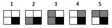
In each of the options you need to draw a specific set of images:
1. a, b, c, d1, d2
2. a, c, d2
3. a, c
...
An example of drawing, where the block segments are marked with different colors:
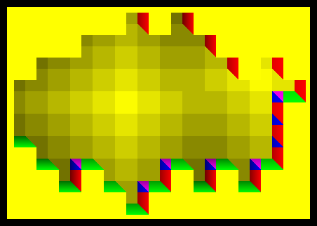
The values of the visible edges of the block were calculated at the stage of generating the landscape, which means that when drawing it was necessary only to draw what was necessary.
About random numbers
To generate “random” numbers, a class was written that generated a set of numbers based on a given string (seed) and an additional parameter. For example, when generating caves, a combination of seed and “caves” was used, for trees - seed and “trees”. This approach provided an opportunity to turn off the generation of a specific area (for example, not to generate blocks of coal or iron), but not to affect the appearance of the other elements, which are based on random numbers.
I built the algorithm on the crc32 checksum calculation algorithm, since at the same time, it allowed me to get a number from any data and I had its realization on hand.
Briefly about the results
Application installations per year: 16553 (+ 81 (paid)):
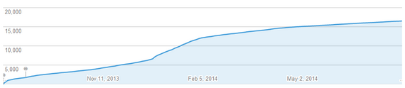
The total income from the application amounted to 2794.91 rubles . In general, if I earned a living by writing bicycles, then I would have died of starvation.
On the development process, I can say that it was very interesting to solve problems that we usually do not encounter in our work. Of course, it was possible to take one of the ready-made engines and, based on it, to do something similar, with an honest 3d and without the described perversions, but again I hope that this will push someone else to create something with their own hands, and not just using ready-made frameworks and libraries.
Thank you all for your attention!
Source: https://habr.com/ru/post/231787/
All Articles