Task “Reliability of Logic Circuits”
 Combinational logic circuits are part of all modern processors and other electronic means of information processing. Processors are used everywhere and are continuously becoming more complex. The number of transistors in the modern processor has already exceeded 2 billion ? And it seems that growth does not plan to stop. At the same time, technologically the production processes of processors are reduced. Transistors are becoming less and more vulnerable to external influences. And now, not even the strongest external radiation and magnetic fields can lead to short-term changes in logical values in microelectronic circuits. This problem is particularly relevant in space and other reliability-critical systems. In this task, we pose the question: how, knowing the logical purpose of a circuit, is to make it more resistant to external influences? Your task will be to develop an algorithm for creating such a stable scheme.
Let a logical scheme, without feedback, be given, consisting of the following 6 elements:
| Title | Description | Operation | Picture |
|---|---|---|---|
| INV | inverter | OUT =! A | 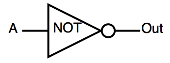 |
| AND | logical "and" | OUT = A & B | 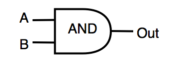 |
| OR | logical "OR" | OUT = A | B | 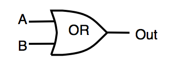 |
| NAND | inverted AND | OUT =! (A & B) | 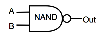 |
| NOR | inverted OR | OUT =! (A | B) |  |
| XOR | exclusive "OR" | OUT = A ^ B |  |
The circuit is affected by environmental noise, which with some probability changes the logical value of the valves to the opposite. It is necessary to construct a circuit that performs the same logical function as the original, but less susceptible to failure. According to the conditions of the problem, the scheme that you designed should be no more than “ K ” times greater than the original in area.
One of the parameters that characterize the stability of logic circuits to failures is COF - "The overall stability of the circuit to errors." COF is calculated as the ratio of the number of correct results of the circuit (all outputs of the circuit must have the correct value) to the total number of tests performed. Accordingly, for the most reliable schemes, COF tends to 1.
Each logic gate of the circuit is characterized by the following parameters: S is the gate area, p is the probability of failure in percent under the current external conditions.
Input data
The first line contains the number Z - the number of tests ( Z <400). Next comes the Z tests.
The first line of each test contains the number K (2.0 ≤ K ≤ 20.0) - the maximum redundancy of the circuit over the area.
The next 6 lines contain two numbers each of area S (1 ≤ S ≤ 100) and the probability of failure q (0 ≤ q ≤ 20) in percent, the parameters of each of the logical elements in the following order: INV, AND, OR, NAND, NOR, XOR.
The next line contains the number “ I ” (0 < I <250) - the number of circuit inputs, followed by I lines of no more than 20 characters each separated by spaces - the names of the input nodes of the circuit.
The next line contains the number “ O ” (0 < O <150) - the number of circuit outputs, followed by O lines of no more than 20 characters each separated by spaces - the names of the output nodes of the circuit.
The following is the number of logic gates in the circuit N (1 < N <5000), followed by N lines describing each gate.
The description of each valve begins with its type, followed by the names of the input nodes, then the name of the output node
')
Output
For each test it is necessary to display the description of the circuit in the following format. On the first line, the number N (1 < N <100000) is the number of gates in the resulting circuit. The following are N - lines with valve descriptions. The description of each valve begins with its type, followed by the names of the input nodes, then the name of the output node.
Scoring
The number of points Score is summarized in all tests. The number of points received for the test will be equal to the COF value calculated for your scheme. Is COF calculated using the Monte-Carlo method ? in two stages:
1) At the first stage, the program judge determines that your scheme works identically to the original. Both test circuits are fed the same test sequences (several thousand times) and the logical values at the circuit outputs are compared. If the logical values differ, you will get the status Wrong Answer.
2) at the second stage, the judge will randomly invert the values on the gates of your circuit and compare the values on your circuit and on the standard circuit, according to the given probabilities. If at least one of the outputs will be different, the counter of "incorrect answers" will increase. The following formula is used for the calculation: COF = ( TT - INC ) / TT , where:
TT - the number of tests with at least one embedded error
INC - the number of tests where at least one output of the circuit showed an error
The same program, the judge checks that the redundancy scheme does not exceed the specified.
Restrictions on the decision
- The size of the program is no more than 50 Kb
- Execution time not more than 50 seconds
- More than 40 programming languages are supported (C / C ++, Java, Pascal, etc.)
Example
Input data:
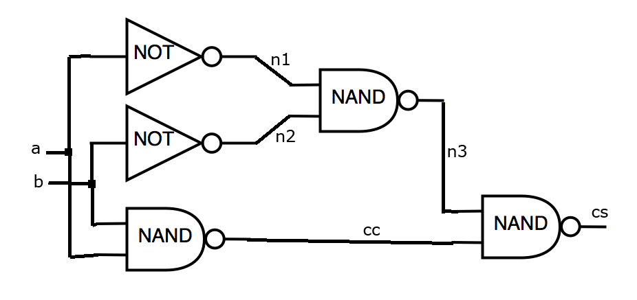
Let the following logic scheme be given (see figure). The required redundancy should not be more than 4.1 times. The scheme is built on the library, which has:
INV has an area of 50 and the probability of failure is 3%
AND has an area of 60 and the probability of failure is 3.1%
OR has an area of 60 and the probability of failure is 3.2%
NAND has an area of 70 and the probability of failure is 3.3%
NOR has an area of 70 and the probability of failure is 3.4%
XOR has an area of 70 and the probability of failure is 3.5%
The input file for this task will look like this:
  one
 5.1
 50.0 3.0
 60.0 3.1
 60.0 3.2
 70.0 3.3
 70.0 3.4
 70.0 3.5
 2 ab
 2 cs cc
 five
 INV a n1
 INV b n2
 NAND ab cc
 NAND n1 n2 n3
 NAND n3 cc cs
Output:
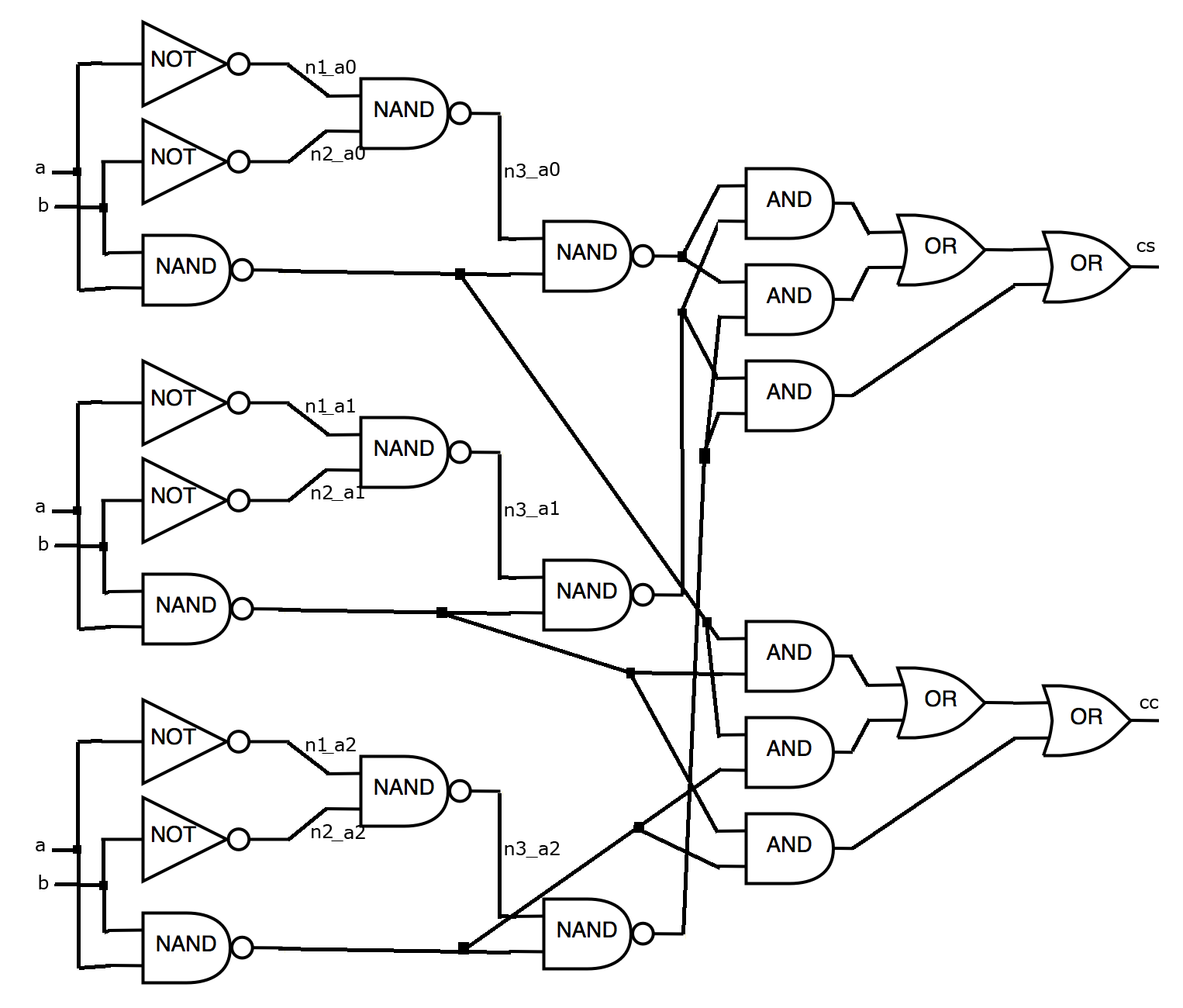
Let our algorithm use the standard method of triplication and the choice of a logical value that is used on a larger number of outputs (Triple Modular Redundancy (TMR)) ? . In this case, the output file can be written as follows:
  25
 INV a n1_a0
 INV a n1_a1
 INV a n1_a2
 INV b n2_a0
 INV b n2_a1
 INV b n2_a2
 NAND ab cc_a0
 NAND ab cc_a1
 NAND ab cc_a2
 NAND n1_a0 n2_a0 n3_a0
 NAND n1_a1 n2_a1 n3_a1
 NAND n1_a2 n2_a2 n3_a2
 NAND n3_a0 cc_a0 cs_a0
 NAND n3_a1 cc_a1 cs_a1
 NAND n3_a2 cc_a2 cs_a2
 AND cs_a0 cs_a1 cs_3_0_and_0_out
 AND cs_a0 cs_a2 cs_5_0_and_0_out
 AND cs_a1 cs_a2 cs_6_0_and_0_out
 OR cs_3_0_and_0_out cs_5_0_and_0_out cs_0_or_0_out
 OR cs_0_or_0_out cs_6_0_and_0_out cs
 AND cc_a0 cc_a1 cc_3_0_and_0_out
 AND cc_a0 cc_a2 cc_5_0_and_0_out
 AND cc_a1 cc_a2 cc_6_0_and_0_out
 OR cc_3_0_and_0_out cc_5_0_and_0_out cc_0_or_0_out
 OR cc_0_or_0_out cc_6_0_and_0_out cc
Picture for the output file
Scoring:
For this decision, after the simulation, 0.682661 points will be awarded.
Sending Solutions
Submit Solution * | Sent Solutions Tape | Best solutions |
* - to send an account is required in the SPOJ system (Shere Online Judge) [ Registration ].
Useful materials
In order not to write programs from scratch, you can use ready-made works:
1) A simple solution to the problem in C \ C ++ - the program reads the data and displays the scheme as it is, without any changes.
2) Judge in C \ C ++ - a program that is used on the server to evaluate the solution of the problem. Can be used locally to test the effectiveness of their decisions.
3) Test data set - a set of 102 test schemes, similar to a closed set on the server.
Authors : Soloviev R.A., Telpukhov D.V.
Source: https://habr.com/ru/post/231775/
All Articles