3D printer without a computer
Hello, dear habravchane!
That ended my move, the candidate minimum was handed over, the first plastic coil was over and it was time to write the promised article about the e-stuff of my printer.
This article will discuss the automation of my PRUSA I3 3D printer, namely the connection of the screen, buttons (instead of the encoder) and the card reader and the power supply system for all additional electronics.
For details, I ask under the cat.
I would like to make a reservation right away that I took the items for these fees from my inventory. What was at hand.
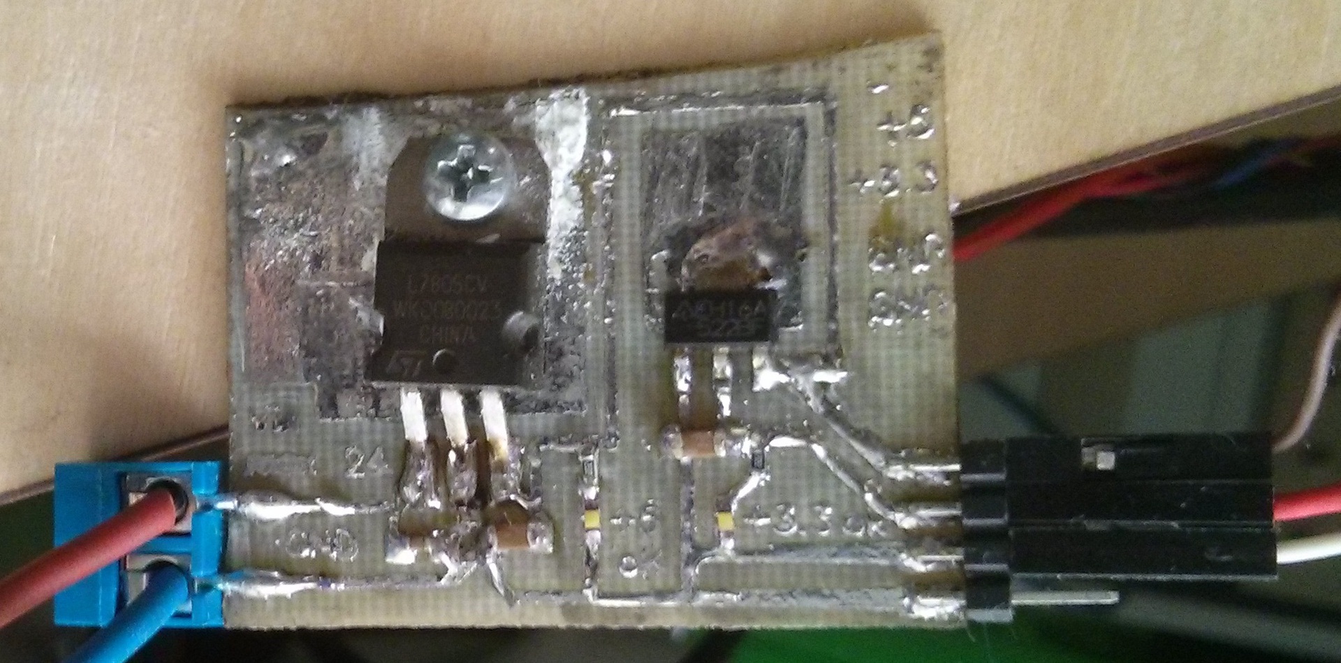
It's simple. A 5 volt stabilizer (I took a L7805CV with an output current of up to 1.5A) to power the arduin and the display. Strapping - two capacitors. The stabilizer is connected to 12 volts. From it through the resistor we connect the LED to indicate the operation. The 3.3 volt voltage stabilizer (LD1117A33 with an output current up to 1A) connects the power supply to the SD card to 5 volts. Piping is the same - two capacitors (well, by analogy, a LED through a resistor).
Specific values for capacitors are selected according to the specification of stabilizers, the values of the resistors for the current consumption of the diodes and the supply voltage (well, or empirically).
On the RAMPS there is a place for soldering the diode D1. When it is connected to the pin Vin, the Arduin is fed 12 volts and goes to the stabilizer on the Arduin. At first I soldered it, and it all even worked together, but after a few minutes the printer just turned off and it was impossible to turn it on without connecting the USB cable (probably, the stabilizer overheated or burned out). Therefore, it was decided to pull out the diode and connect an external stabilizer.
')
To power the memory card, you need 3.3 volts, the logic levels of the card are also 3.3 volts. In the finished modules called SDRamps, a stabilizer is used (we have already assembled it) and a level converter chip (5-> 3.3). Since I did not have such a chip, it was therefore decided to use a conventional resistive divider.
The card is connected in SPI mode. Used: 3 lines SCK, CS, MOSI from arduin to the map through dividers; line MISO directly from the map to arduine; 3.3 volts power supply is also connected; land; and I also connected the card availability detector. The cardholder was dropped from the old smartphone, but you can use the SD-microSD adapter (but it does not have a card presence detector).
Any character display, ranging from 2 lines by 16 characters, will do. The more rows, the more data on it can be displayed. You can also connect the graphic display SPI LCD 128x64 (Controller ST7565R graphic Display Family). We connect according to the scheme described here . 4 data lines, RS, Enable, 5 volts, ground and a 10kΩ trimmer for contrast adjustment.
Since I did not find the encoder, I decided to do with the button interface. Any 3 buttons will do. True, you will have to edit the firmware, but more on that later.
As I mentioned in the last article, this very mosfets are very hot due to improper operation. I replaced it with the APM2509N, taken from a video card. Were also increased the power paths of the table. Scalpel neatly cut the lacquer coating and soldered with a thick layer of solder. The previous mosfet was heated in such a way that after 30-50 minutes it was possible to burn a finger on it. A new maximum heated to 38 degrees for 6 hours printing. And yes, the mosfet stands without a radiator.
The table now heats up to 100 ° C in 15-17 minutes (earlier than 30 minutes). And the LED on the table began to shine somehow brighter (or maybe it only seems).
The output from the 5 volt stabilizer is connected to any pin 5V on the RAMPS.
The cardriader is connected to the AUX-3 connector (RAMPS pins on the left, SD on the right):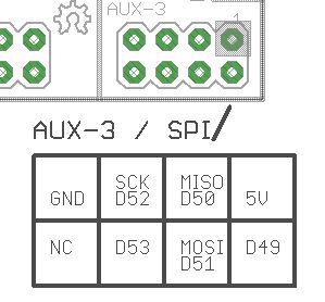
pin D50 (MISO) - DO (MISO);
pin D51 (MOSI) - divider - DI (MOSI);
pin D52 (SCK) - divider - SCK;
pin D53 - divider - CS;
3.3 volts (with stabilizer) - VCC;
GND - GND (VSS);
and in the presence of SD Detect we connect the pin D43 of the AUX-4 connector to it.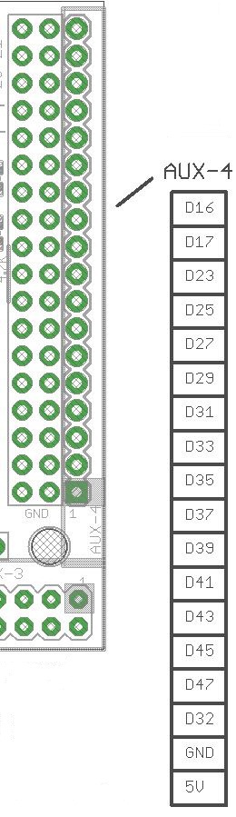
The buttons and the display are connected to the AUX-4 connector.
Display (on the left is the RAMPS pins, on the right is the display (the data bus starts with D0)):
pin D16 - RS;
pin D17 - Enable (E);
pin D23 - Data 4 (D4);
pin D25 - Data 5 (D5);
pin D27 - Data 6 (D6);
pin D29 - Data 7 (D7);
5 volts - VDD;
GND - VSS;
The trimmer resistor is connected to 5 volts and ground, and the output to pin VO (contrast);
Pin RS display connect to the ground;
In the presence of illumination, we connect 5 volts through a 1.8k ohm resistor and ground.
The buttons are connected to the ground and:
pin D31 - Up;
pin D33 - Down;
pin D35 - Click;
By default, these pins are configured in the firmware. To connect to others, you need to correct the file pins.h in the firmware.
To start support for SD cards, character display and buttons in the firmware, uncomment the line in the configuration.h file:
At the same time, ULTIPANEL, NEWPANEL, SDSUPPORT and ULTRA_LCD are automatically detected, which are responsible for the operation of the display, buttons and the card reader.
The name of the printer displayed on the screen is given by the line:
The number of characters and lines of the display is set by the parameters LCD_WIDTH and LCD_HEIGHT, respectively:
To support buttons instead of an encoder in the ultralcd.cpp file
With proper assembly, after pouring the firmware, you can remove the USB cable in the drawer and print from the SD card.
That's all for now. As usual, I look forward to questions and comments.
PS In the near future I plan to put the auto-calibration of the table with the servomotor. And assemble the frame of the second printer.
That ended my move, the candidate minimum was handed over, the first plastic coil was over and it was time to write the promised article about the e-stuff of my printer.
This article will discuss the automation of my PRUSA I3 3D printer, namely the connection of the screen, buttons (instead of the encoder) and the card reader and the power supply system for all additional electronics.
For details, I ask under the cat.
I would like to make a reservation right away that I took the items for these fees from my inventory. What was at hand.
Let's start with food.
It's simple. A 5 volt stabilizer (I took a L7805CV with an output current of up to 1.5A) to power the arduin and the display. Strapping - two capacitors. The stabilizer is connected to 12 volts. From it through the resistor we connect the LED to indicate the operation. The 3.3 volt voltage stabilizer (LD1117A33 with an output current up to 1A) connects the power supply to the SD card to 5 volts. Piping is the same - two capacitors (well, by analogy, a LED through a resistor).
Specific values for capacitors are selected according to the specification of stabilizers, the values of the resistors for the current consumption of the diodes and the supply voltage (well, or empirically).
On the RAMPS there is a place for soldering the diode D1. When it is connected to the pin Vin, the Arduin is fed 12 volts and goes to the stabilizer on the Arduin. At first I soldered it, and it all even worked together, but after a few minutes the printer just turned off and it was impossible to turn it on without connecting the USB cable (probably, the stabilizer overheated or burned out). Therefore, it was decided to pull out the diode and connect an external stabilizer.
')
Card reader
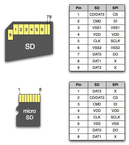
To power the memory card, you need 3.3 volts, the logic levels of the card are also 3.3 volts. In the finished modules called SDRamps, a stabilizer is used (we have already assembled it) and a level converter chip (5-> 3.3). Since I did not have such a chip, it was therefore decided to use a conventional resistive divider.
The card is connected in SPI mode. Used: 3 lines SCK, CS, MOSI from arduin to the map through dividers; line MISO directly from the map to arduine; 3.3 volts power supply is also connected; land; and I also connected the card availability detector. The cardholder was dropped from the old smartphone, but you can use the SD-microSD adapter (but it does not have a card presence detector).
Screen
Any character display, ranging from 2 lines by 16 characters, will do. The more rows, the more data on it can be displayed. You can also connect the graphic display SPI LCD 128x64 (Controller ST7565R graphic Display Family). We connect according to the scheme described here . 4 data lines, RS, Enable, 5 volts, ground and a 10kΩ trimmer for contrast adjustment.
Buttons
Since I did not find the encoder, I decided to do with the button interface. Any 3 buttons will do. True, you will have to edit the firmware, but more on that later.
Mosfet on a heated table
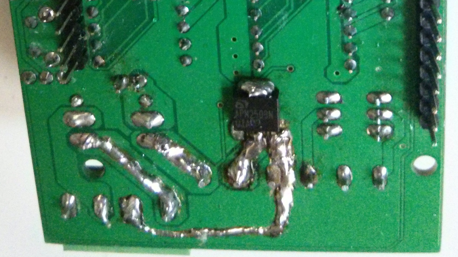
As I mentioned in the last article, this very mosfets are very hot due to improper operation. I replaced it with the APM2509N, taken from a video card. Were also increased the power paths of the table. Scalpel neatly cut the lacquer coating and soldered with a thick layer of solder. The previous mosfet was heated in such a way that after 30-50 minutes it was possible to burn a finger on it. A new maximum heated to 38 degrees for 6 hours printing. And yes, the mosfet stands without a radiator.
The table now heats up to 100 ° C in 15-17 minutes (earlier than 30 minutes). And the LED on the table began to shine somehow brighter (or maybe it only seems).
We connect
The output from the 5 volt stabilizer is connected to any pin 5V on the RAMPS.
The cardriader is connected to the AUX-3 connector (RAMPS pins on the left, SD on the right):
pin D50 (MISO) - DO (MISO);
pin D51 (MOSI) - divider - DI (MOSI);
pin D52 (SCK) - divider - SCK;
pin D53 - divider - CS;
3.3 volts (with stabilizer) - VCC;
GND - GND (VSS);
and in the presence of SD Detect we connect the pin D43 of the AUX-4 connector to it.
The buttons and the display are connected to the AUX-4 connector.
Display (on the left is the RAMPS pins, on the right is the display (the data bus starts with D0)):
pin D16 - RS;
pin D17 - Enable (E);
pin D23 - Data 4 (D4);
pin D25 - Data 5 (D5);
pin D27 - Data 6 (D6);
pin D29 - Data 7 (D7);
5 volts - VDD;
GND - VSS;
The trimmer resistor is connected to 5 volts and ground, and the output to pin VO (contrast);
Pin RS display connect to the ground;
In the presence of illumination, we connect 5 volts through a 1.8k ohm resistor and ground.
The buttons are connected to the ground and:
pin D31 - Up;
pin D33 - Down;
pin D35 - Click;
By default, these pins are configured in the firmware. To connect to others, you need to correct the file pins.h in the firmware.
To start support for SD cards, character display and buttons in the firmware, uncomment the line in the configuration.h file:
#define REPRAP_DISCOUNT_SMART_CONTROLLER At the same time, ULTIPANEL, NEWPANEL, SDSUPPORT and ULTRA_LCD are automatically detected, which are responsible for the operation of the display, buttons and the card reader.
The name of the printer displayed on the screen is given by the line:
#define CUSTOM_MENDEL_NAME "This Mendel" The number of characters and lines of the display is set by the parameters LCD_WIDTH and LCD_HEIGHT, respectively:
set the display size
#ifdef ULTIPANEL // #define NEWPANEL //enable this if you have a click-encoder panel #define SDSUPPORT #define ULTRA_LCD #ifdef DOGLCD // Change number of lines to match the DOG graphic display #define LCD_WIDTH 20 #define LCD_HEIGHT 5 #else #define LCD_WIDTH 20 // #define LCD_HEIGHT 4 // #endif #else //no panel but just LCD #ifdef ULTRA_LCD #ifdef DOGLCD // Change number of lines to match the 128x64 graphics display #define LCD_WIDTH 20 #define LCD_HEIGHT 5 #else #define LCD_WIDTH 16 #define LCD_HEIGHT 2 #endif #endif #endif To support buttons instead of an encoder in the ultralcd.cpp file
find strings
//manage encoder rotation uint8_t enc=0; if(buttons&EN_A) enc|=(1<<0); if(buttons&EN_B) enc|=(1<<1); if(enc != lastEncoderBits) { switch(enc) { case encrot0: if(lastEncoderBits==encrot3) encoderDiff++; else if(lastEncoderBits==encrot1) encoderDiff--; break; case encrot1: if(lastEncoderBits==encrot0) encoderDiff++; else if(lastEncoderBits==encrot2) encoderDiff--; break; case encrot2: if(lastEncoderBits==encrot1) encoderDiff++; else if(lastEncoderBits==encrot3) encoderDiff--; break; case encrot3: if(lastEncoderBits==encrot2) encoderDiff++; else if(lastEncoderBits==encrot0) encoderDiff--; break; } } lastEncoderBits = enc; change to
//manage encoder rotation uint8_t enc=0; if(buttons&EN_A) { encoderDiff = 1; delay(10); } if(buttons&EN_B){ encoderDiff = -1; delay(10); } With proper assembly, after pouring the firmware, you can remove the USB cable in the drawer and print from the SD card.
That's all for now. As usual, I look forward to questions and comments.
PS In the near future I plan to put the auto-calibration of the table with the servomotor. And assemble the frame of the second printer.
Source: https://habr.com/ru/post/231743/
All Articles