Connecting the display of the DVD player to the microcontroller

I'll start with the background, why do I need all this? I set out to make myself a HTPC computer based on the enclosure from the Daewoo DV-500 DVD player, outwardly I like it, and there is enough free space in it to install the necessary hardware inside. But above all, I decided to leave the native indicator and use it to display various information. How I connected the display to the microcontroller and decrypted the protocol of an exchange of this display, will go in this article.
Such work should be started with information retrieval, first of all I found the player's circuit; I was surprised that there were no problems with this. According to the scheme, I was able to understand what I have to work with, but I could not immediately find the descriptions on the display controller, since On the diagram, it is signed incorrectly. Unfortunately, I found the documentation for the controller at the last moment, by chance, but by that time I had almost completely disassembled the protocol.
So, what do we have:
')

We have a NEC D16312 VFD display controller (note how the controller is signed on the circuit, it’s not surprising that I couldn’t immediately find the info about it), with the VFD display, keyboard matrix and LED connected to it. With the "outside world" controller is connected via a serial interface via connector CN1.
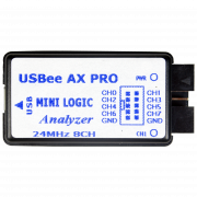
To intercept messages from the mainboard controller to the display controller, I will use a logic analyzer. I, for example, use the Chinese clone USBee AX PRO, it performs its functions perfectly well and is inexpensive.
We connect the Data, Clk and Cs pins to any three pins of the logic analyzer, do not forget to also connect the earth. Next, we connect the analyzer via USB to the computer and run the USBee Suite (I omit the installation process of the drivers and software for the logic analyzer, this is beyond the scope of the article). In the settings for Speed and Samples we set the following parameters: Sample Rate - 2Msps, Buffer Size - 10M samples. This will be enough to capture an exchange frame size of 5 seconds.
My further actions are as follows: I make a single capture (the Capture Once button) and immediately turn on the player. As soon as the first information appeared on the screen, I turn off the capture. After doing such actions for different versions of the displayed text, I began to analyze the information received.
So, what are the patterns in all the sending teams. The first thing that caught my eye right away was the frequency of sending a command with code 0x42 and three empty bytes after it. The team has a strict periodicity of appearance even when the video player is at rest. I assumed that this is a command for polling the keyboard, checking the theory is very easy, I pinch any button on the player and capture the frame in the program.
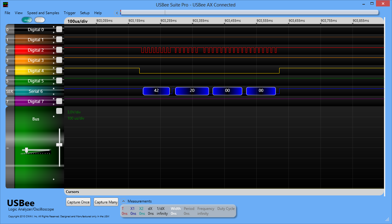
Immediately after the byte 0x42, the non-zero byte appeared, but before it was 0! Thus, 0x42 is a keyboard polling command that is sent by the mainboard controller to the display controller and, in response to this command, the display controller responds with the key code (or 0 if none is pressed).
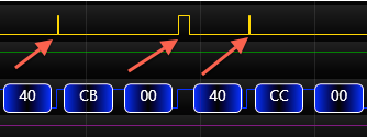
The next in line was a team with code 0x40, it appeared only when information was displayed on the screen. After it, there are always two bytes, the first byte always starts with 0xCX, where X is a changing value. The third byte has arbitrary values, but the main thing is that when it is first turned on it is always 0
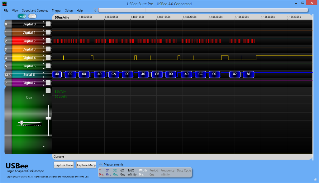
This screenshot shows that the second byte grows with each sending of the 0x40 group, most likely it sets the address of the character and the value of the character is written in the third byte. In this case, 0 clears the character. Always after sending all groups with code 0x40, two bytes 0x02 0x8F will follow.

Well, the last group of data is the command starting with the code 0x41 and the subsequent zero byte after it. The command appears only when the video player is first turned on.
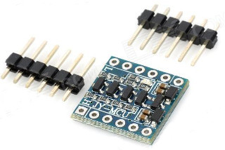
Data analysis has drawn a more or less clear picture of the controller, it remains only to check everything in practice. I used the LPCXpresso debug handkerchief, which I received in a free-fall manner as part of some kind of competition from NXP. The shawl is equipped with a simple 32-bit LPC1114 controller. Since Since the controller is powered by 3.3V, and the display controller D16312 is from 5 volts, I did not decide to connect their outputs directly. The microcontroller pins may be tolerant to 5V, but I had a 3.3-5V matching handkerchief and I used it.
So, from the connector going to the main board, we extract 3 wires responsible for the Data, Cs and Clk pins, 1, 2 and 3, respectively. GND and + 5V VCC. For the first time, I attached three contacts extracted from the main board with the logic analyzer in order to debug the transmitted information.

This is how I look like with a debugging

All the iron part is ready, it's time to start the software. To begin with, we will write a program that will repeat the data obtained during the analysis. For LPCXpresso, the Eclipse-based LPCXpresso IDE is used. We start, specify the path to our new workspace and import 2 standard libraries CMSIS_CORE_LPC11xx and LPC11xx_cmsis2_Lib into it, we will need them for development. Next, create a new project File-> New-> C / C ++ -> LPCXpresso C Project, then LPC11 / LPC12 -> LPC11xx / ... -> C Project. Set the project name and in the next window select the target controller, in my case it is LPC1114 / 302. At the next step, the library CMSIS_CORE_LPC11xx should appear in the list, since we imported it earlier. In the DSP library job window, we change nothing and in the next step we leave everything by default, click Finish.
Add the following code to the generated file <project name> .c
#ifdef __USE_CMSIS #include "LPC11xx.h" #include "clkconfig.h" #include "gpio.h" #endif #include <cr_section_macros.h> void Delay(int32_t ticks); void BeginCommand(uint8_t cmd, uint8_t isSingle); void EndCommand(); void Clock(); void WriteData(uint8_t data); #define PORT 3 #define DATA_BIT 2 #define CLK_BIT 0 #define CS_BIT 1 int main(void) { GPIOInit(); // Set pins to output GPIOSetDir(PORT, CLK_BIT, 1); GPIOSetDir(PORT, CS_BIT, 1); GPIOSetDir(PORT, DATA_BIT, 1); while(1) { BeginCommand(0x40, 1); BeginCommand(0xC0, 0); WriteData(0xFF); EndCommand(); BeginCommand(0x02, 1); BeginCommand(0x8F, 1); Delay(3000000); } return 0 ; } void Delay(int32_t ticks) { volatile int32_t i = ticks; while(i--); } void BeginCommand(uint8_t cmd, uint8_t isSingle) { GPIOSetValue(PORT, CLK_BIT, 1); GPIOSetValue(PORT, CS_BIT, 0); Delay(10); WriteData(cmd); if (isSingle) { EndCommand(); } } void EndCommand() { GPIOSetValue(PORT, CLK_BIT, 1); GPIOSetValue(PORT, CS_BIT, 1); Delay(10); } void Clock() { Delay(10); GPIOSetValue(PORT, CLK_BIT, 0); Delay(10); GPIOSetValue(PORT, CLK_BIT, 1); } void WriteData(uint8_t data) { GPIOSetDir(PORT, DATA_BIT, 1); uint8_t i = 0; for (i = 0; i < 8; ++i) { uint8_t isSet = (data & 0x01); GPIOSetValue(PORT, DATA_BIT, isSet); Clock(); data = data >> 1; } } Here we see several functions for working with a serial port. At the very top of the file, the port and pin settings for data, synchronization and strobe are specified. In my case, everything hangs on port 3, pin 2 is responsible for the Data signal, 0 is synchronization and 1 is gating.
The fc BeginCommand sends a command to the port, this f-c has a second interesting parameter. If you look at the graphs of signals above, you can see that the gating signal is set to the active (low) level, before sending data, and changes between two independent commands. But it does not switch if data should be transmitted after sending the command
So, the second parameter says that the command is atomic if isSingle == 1. For the case of non-atomic commands, the EndCommand function is intended, which should be called after sending the data.
Sending the data is done in the WriteData function, in turn, bit-for-bit, starting with the youngest, we pass the information to the Data pin. Each data entry is accompanied by a synchronization signal, the Clock function generates it.
In the f-main function, we first initialize the work with the I / O inputs, then expose the Data, Clk and Cs pins for output. In an infinite loop, we imitate the commands that were obtained earlier in the data analysis stage. So we sent a 0x40 0xC0 0xFF 0x02 0x8F data sequence to the display controller, and the controller responded with the output _8

So it was found that the command:
- 0x42 - is responsible for handling the keyboard. After it is sent to the display controller, you need to set the Data port to the input and read data from it, previously synchronized with the signal Clk
- 0x40 - a command to write data to the display, after it a command should be written to specify the address of the symbol, and after the address is specified, data is written
- 0x41 is a command to control the LED, after it comes a data byte which LED should be on or not
You can find more detailed information in the manual for this display controller D16312, where they describe how commands should be formed. Well, I designed all the work in a small library that lies on the githaba . The library allows you to display text, manage special characters, fill in the drive symbol as a percentage, read the keyboard, change the display brightness and control the LED. That's all, I hope someone this reading matter will be useful and interesting. And I'll leave a video for a snack, with a demonstration of the library
Source: https://habr.com/ru/post/231735/
All Articles