Experience another engineering investigation
We had the opportunity to hold another small but extremely instructive tactical exercise.
The subject of this post was inspired by a mailing from Sherlock Oms - periodically there are stories about nontrivial engineering problems that have arisen when diagnosing various electronic devices. So I thought, why not? Although I understand perfectly well that the subject matter is quite specific, it requires very specific highly specialized knowledge and is unlikely to be interesting to a wide circle of readers, but a narrow circle of connoisseurs of hardware puzzles is able to deliver. So for those who know what a data bus is and how it works, there is a story in which and ships, and shoes, and sealing wax, and cabbage palms.
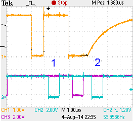
In the process of designing a device on the MK 1986VE1T, about which I already wrote, it became necessary to interact with external FLASH memory chips through a fairly fast interface, preferably parallel. Fortunately, this capability is present in the considered MK, and for organizing access to devices mapped to memory, but not included in the MK itself, you can use the full (32 address bits, 32 data bits, 2 control signals, 4 tracking signals) external bus, and the exchange for the user program looks absolutely transparent. As always, thanks to the developers for including such an option, and, as always, expressing displeasure at the obviously insufficient documentation, although the post is not about that. Due to a number of design and controller features, not the entire width of the data bus was used, but only 8 bits, starting from the 3rd, which is absolutely irrelevant to describe the detected problem. The MC, together with all the output buffers, is powered by +3.3, in addition, to ensure the operation of other devices, the pull-up resistors were connected to the +5 voltage on the data bus. After assembling the prototype of the device, debugging began and the first test examples (of course, or, as they say, of course) did not work, and then they took (hereafter, the plural is used, since we did this work with a young colleague who for some reason does not want to write posts on Habré) oscilloscope and climbed to look tinkers. And it was here that an interesting phenomenon was discovered. The expected waveform of the signals on the data bus should look like this (red and green - it was not I who invented it, it just happened when flooding on Habr):
')
The fragment of the oscillogram marked with the number 2 is the expected behavior of the bus in the absence of an addressed external device (achieved by moving the sample input to an inactive state). MK removes data from the bus (black line in the upper diagram) and the voltage on it begins to pull up to the power through the make-up resistor. After some time, the MC gives the active level (zero) of the read signal (green signal in the lower diagram) and at this moment the external device should transmit data (since it is inactive, the pull-up continues), then after a certain time the active level of the read signal is removed, the external device frees the tire, the further state on the tire is indefinite, in our case the lift continues. Everything is logical and understandable, but the fact is that the diagrams shown at section 1 were initially discovered. In this case, before giving the read signal, the MC gave a high level to the bus and continued to hold it for the duration of the reading and even further, only after a significant time (on the order of milliseconds) the data bus went into a disabled state. Somewhat unexpectedly, but at first I took the situation without proper attention - I decided that somewhere in the settings of the pins there was a mistake to look for (since the program was written by a young colleague, it was easy for me to assume that there were possible errors in it, so if I wrote then the situation would not be so unambiguous :)). Firm confidence in the presence of an error in the settings disappeared after it was ascertained that ALL 16 data lines (out of 32) are configured the same, and only 4 of them are faulty, moreover, these are bits 4.5, 8 and 11.
We think further and experiment. The idea appears that it is impossible to read immediately after writing (this is not reflected in the documentation, but we’ve got used to thinking about something when working with Milander), so we do 2 consecutive readings, in the hope that the second will pass correctly.
data=*buffaddr; data=*buffaddr; And here the most interesting begins - the second reading really goes right, BUT the first one also becomes correct - a very interesting phenomenon - I absolutely can’t imagine its mechanism - that is, I can’t imagine a reasonable mechanism for a subsequent team to influence the previous one. A quick look at the generated assembly code gives a hint - the address of the location of the first reading command has changed due to the peculiarities of the linker operation - is better, the mechanism of address influence on the execution of the command is easier to come up with. In order to investigate the behavior of the MC, we select the fragment relating to the exchange with the external bus from the general program, by removing everything that is unnecessary. And we get another surprise - incorrect reading is not observed even with a single call, although the address of the command remains unchanged. By inserting the deleted fragments back, we find out that when the CRC16 calculation function is connected, incorrect reading is observed, and if it is not available, it is not, and this function obviously doesn’t interact with the external bus and cannot influence reading in reasonable ways. Further experiments have shown that it is not the counting function of the CRC16 as such that is important, but the presence of a block of intermediate amounts in it, moreover, the size of this block, that is, with code:
static CRC16Buff[256]; static CRC16Buff[215]; ( 215) - How can this fragment affect the executable code in a completely different place? We find out that the only change is in the value of the stack, since the required place for global variables has changed. That is, it turns out that incorrect handling occurs when a command is executed from certain places at certain values of the stack, and the number of erroneous bits in a word is small? It's time to remember the first rule of the engineer - "There are no miracles in the world." It can be assumed that this is the remainder of some debugging function VHDL, which signaled certain situations and was not removed from the release. It looks like the thought of a heavily smoked developer, but so far there is no other hypothesis, since we reject divine intervention. Another thought - “here you are, reindeer” - we found the BOOTMARK, although rather meaningless, but who can understand them, the guys from the NSA.
We continue research and are surprised to find that moving a command to different addresses (by adding NOP) does not lead to anything - the error does not appear, or, accordingly, does not disappear for different values of the stack, that is, the address hypothesis should be rejected. But how then does the addition of the second command affect the first? We look at the assembler code more attentively and detect more changes, namely, with single reading, the compiler generates
mov r0, sp ldrh r1,[r4] strh r1,[r0] And with two readings in a row he spent otpimizatsii:
mov r2, sp ldrh r1,[r4] strh r1,{r2] ldrh r1,[r4] strh r1,[r2] It was hard to believe in this, but it is indeed further established that incorrect reading takes place if and only if the register r0 contains a very specific value, and it does not matter whether this register will be used in the future. Compared to the previous completely crazy hypothesis about the relationship of the stack pointer and the command counter, we see clear progress. Further experiments establish that a forced erroneous high level is observed at the data bits for which the units were recorded in the last cycle, and in which in the register r0 units are written moreover, the phenomenon is clearly triggered - occurs when reading for the first time after writing and is held for a certain time, and this time has nothing to do with the frequency of the MC (within the error of the observation Ia), but has a connection with a pronounced crystal temperature (the temperature increases the retention time increases). It can be assumed that the control signal of the output buffer of the upper stage of the data bus has an unforced inactive level, and the signal from the corresponding register bit is induced on it until the capacitance of the leakage currents is recharged. The hypothesis is good, but the trigger point, unfortunately, does not explain if anyone comes up with a more suitable explanation - I ask in the comments. Well, in the practical part, so to speak in the dry residue, before reading the data in the register r0 we write the zero and the bus behaves as it should, which is confirmed by the above oscillogram obtained with the following code
mov r0, #0xFFFFFFFF ; ldrh r1,[r4] ; - 1 strh r1,[r4] ; , - mov r0,#0x00000000 ldrh r1,[r4] ; - 2 By the way, like O'Henry, there were no kings or cabbages.
Source: https://habr.com/ru/post/231373/
All Articles