Home-made bike computer, or how the Arduino hit the street

Hello, Habr! I would like to share my own story about creating a cycle computer. After buying the bike, I decided to somehow fix my progress, but the mobile trackers were not the most convenient solution, and from China I was already flown by the BOGEER 823, which I had ordered in advance, which made a purchase on the spot meaningless. Therefore, I decided to try to make a bike computer with my own hands, at the same time laying the foundation for the expansion: controlling the body kit of the bicycle (front and rear light, bell).
Little preparation
At the heart of any bike computer is a reed switch that captures a wheel turn, and everything else is elementary mathematics ... Of course, I searched the Internet for ready implementations and formulas that I need.
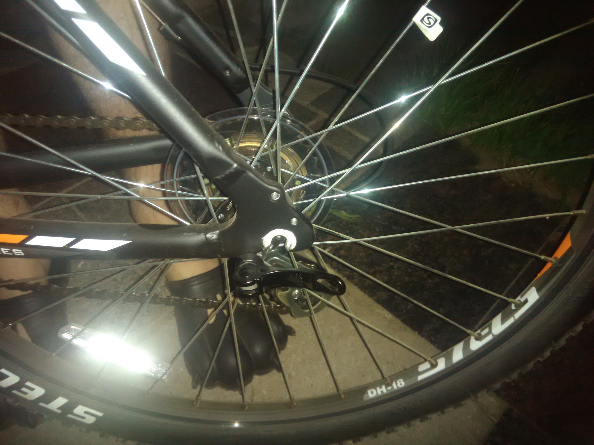
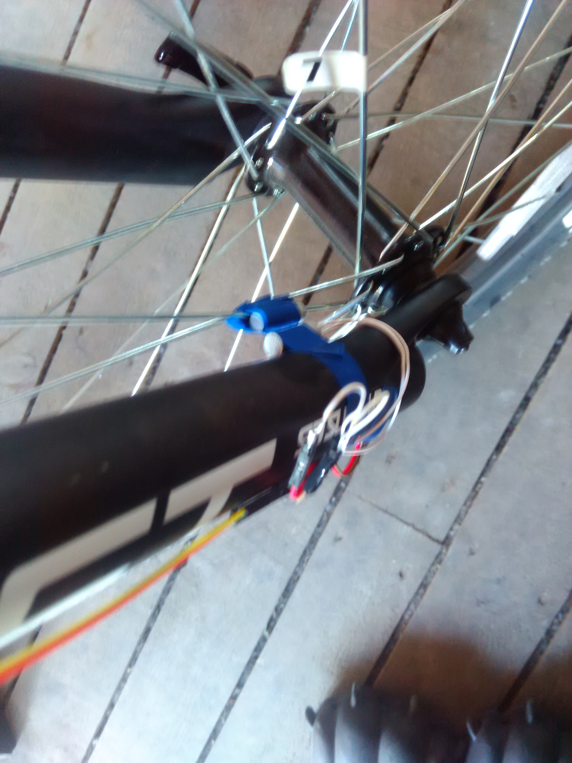
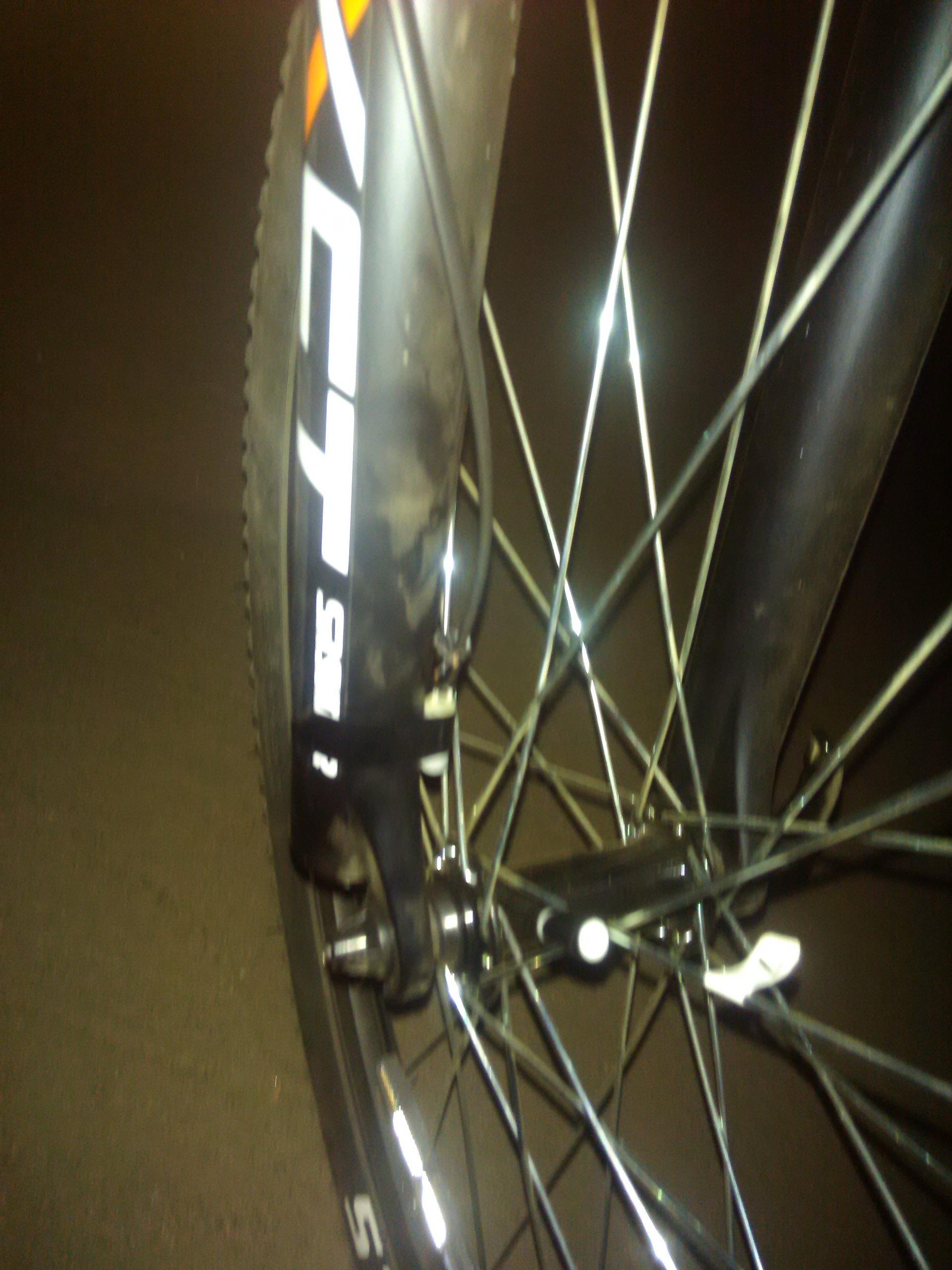
As I already wrote, everything is tied to the reed switch : the magnet is fixed on the spoke, and the reed switch itself is on the "fork". When the magnet on the fork closes the reed switch - this means that the wheel has made a full turn and the bike has traveled a distance equal to:
2 * Pi * R tires
First version
First of all, I made a list of what I needed from the cycle computer:
- Current speed
- The distance of the current trip
- Distance of all trips
- Travel time
- Current time
- Backlight
- The ability to exchange data with a computer via a memory card
Fortunately, all the necessary modules were at hand:
')
- Arduino nano
- Nokia 5110 LCD (blue backlight, via GND)
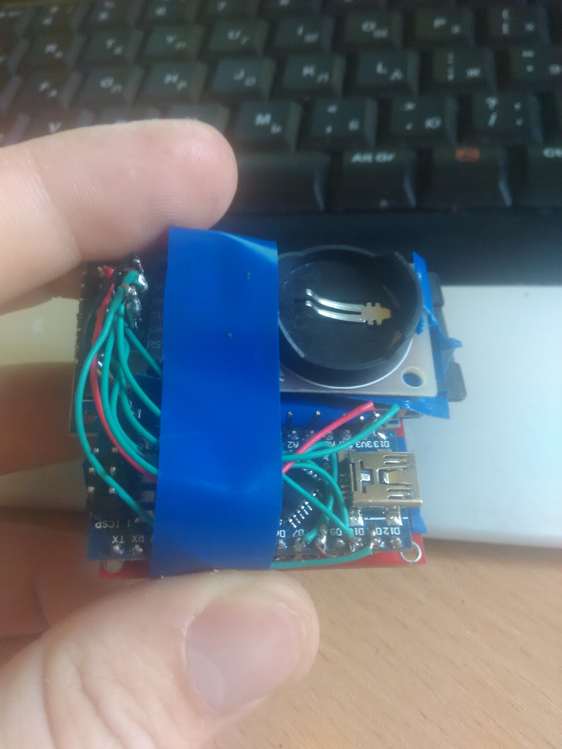
- Soldered clock DS1302
- SD card module
I quickly assembled a sandwich: on top of the screen, the second layer of the SD module and the Arduinka itself, and the clock under it all. It turned out pretty compact. Of course, if I didn’t use ready-made modules, but “crush” and poison boards, I could have won a lot of space.
Result photo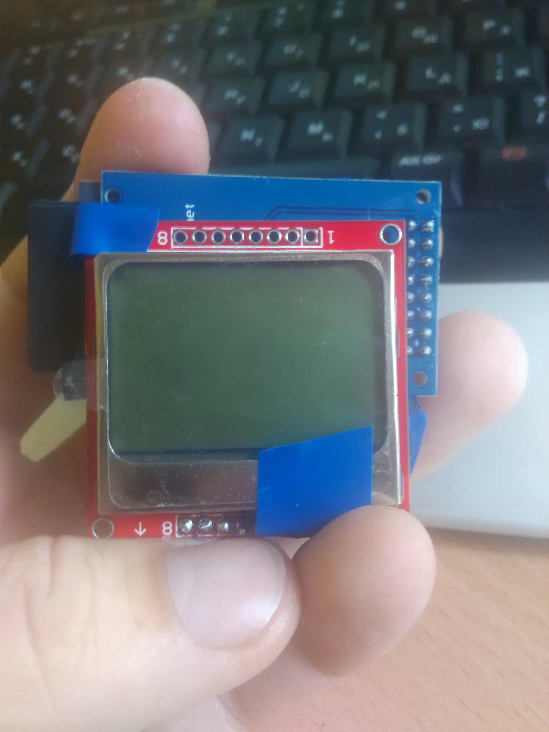

Having connected the reed switch, I started testing the first version of the sketch, which was based on the sketch obtained from the network for working with the display and the English-speaking speedometer .
And how much can you squeeze out of your chair?
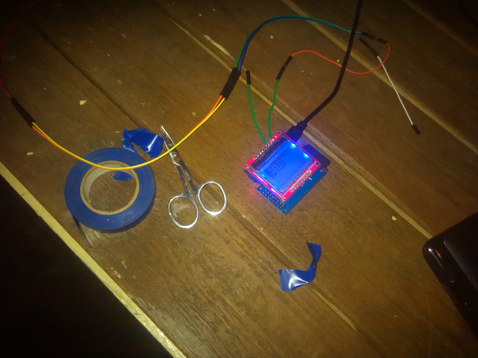
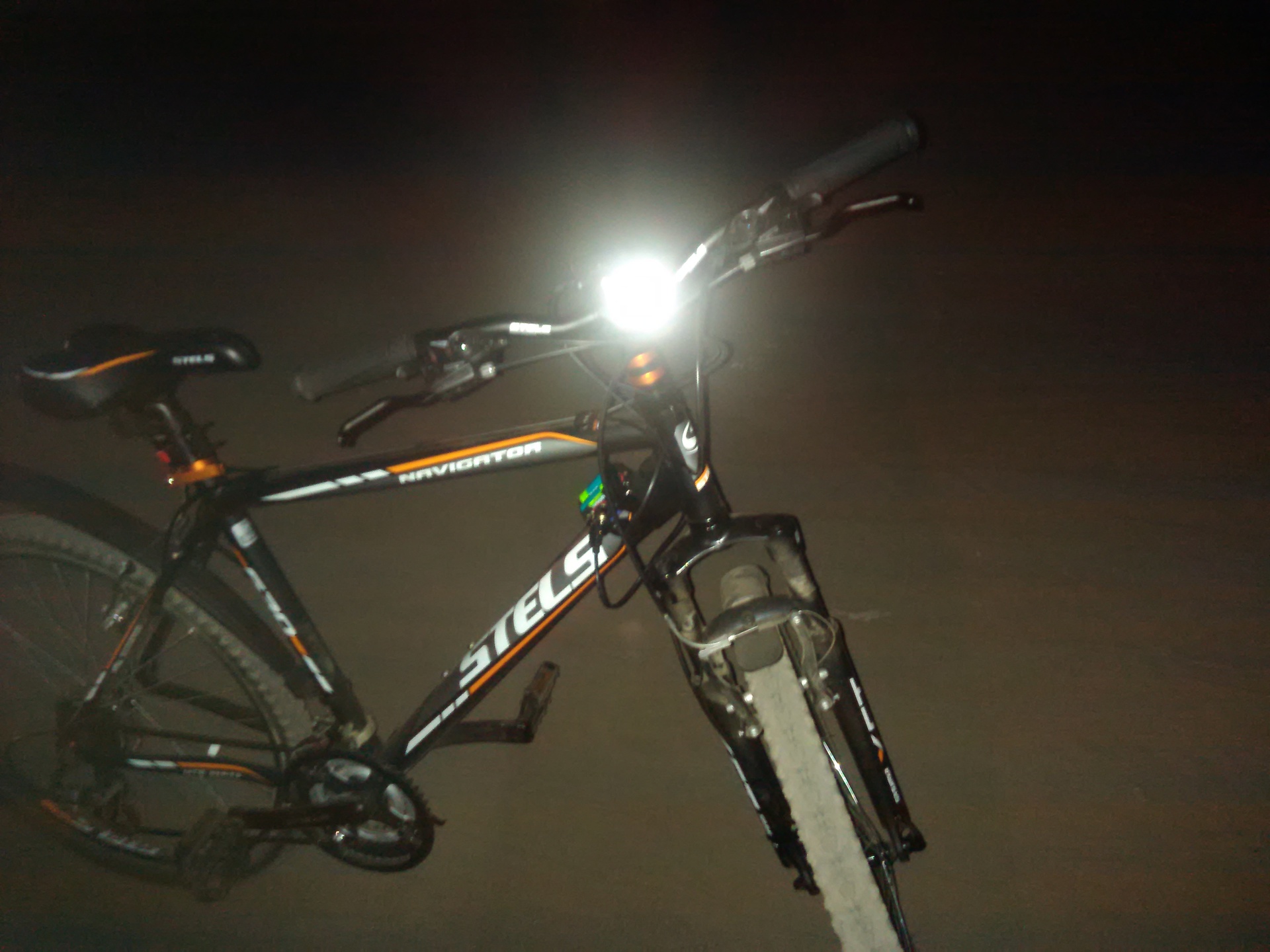
Convinced of the performance of the design, I decided to conduct the first test. I planned power from several AA batteries or a battery, but at that moment they were not at hand ... Believe me, riding a bicycle with a laptop under my arm is still a pleasure.
Photo from the first test
Guess why not the bike does not go back?
Guess why not the bike does not go back?
Testing has borne fruit. I found an error in logic: the signal from the reed switch was always equal to the revolution of the wheel (if the minimum time for a revolution has passed). It seems that everything is correct, but if you stop by fixing the magnet opposite the reed switch, the program thought that you were going very fast.
Second version
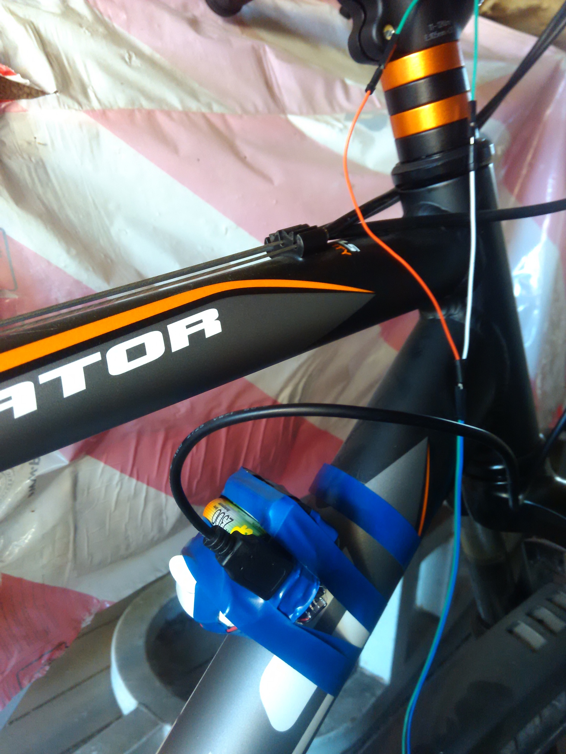
Having slightly modified the program, I assembled a “power unit”: a set of five AA batteries. Before that, I tried to use the crown, but it was not enough for Arduinka with a body kit.
Since my 5110th was on a red substrate, which means that the backlight in it was controlled by a logical zero, and not one, program management through the analog port had to be abandoned and a simple button added.
In addition, the analog port without data gave random values, but this was decided by a simple resistor. But another surprise from the analog port made me break my head: the value of the reed switch when powered by batteries was not the same as when using the USB port.
Photo from the second test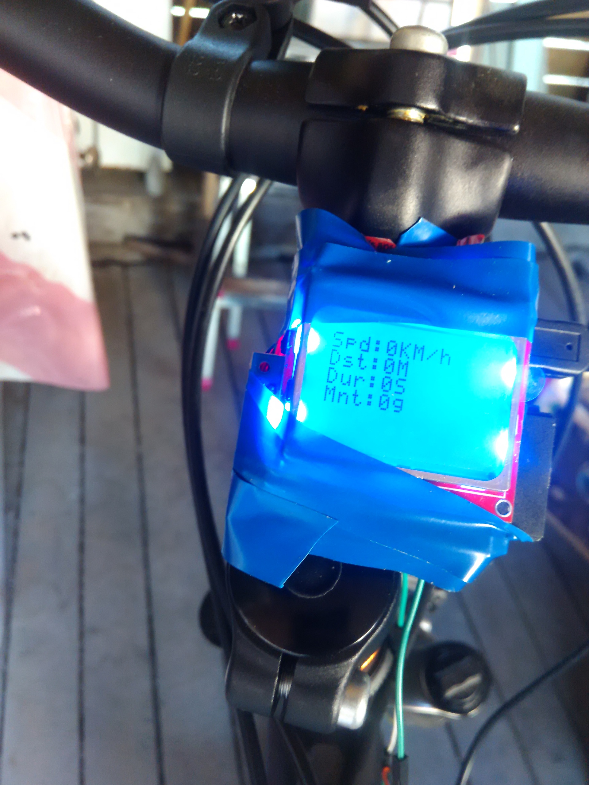
The second test showed the complete system performance. The only problem was an error in the calculations: the radius of the "26 inch wheel" was "13.5" inches. As a result, the odometer lied a bit (thanks to Yandex.Maps for a handy tool for calculating distances).
Third version
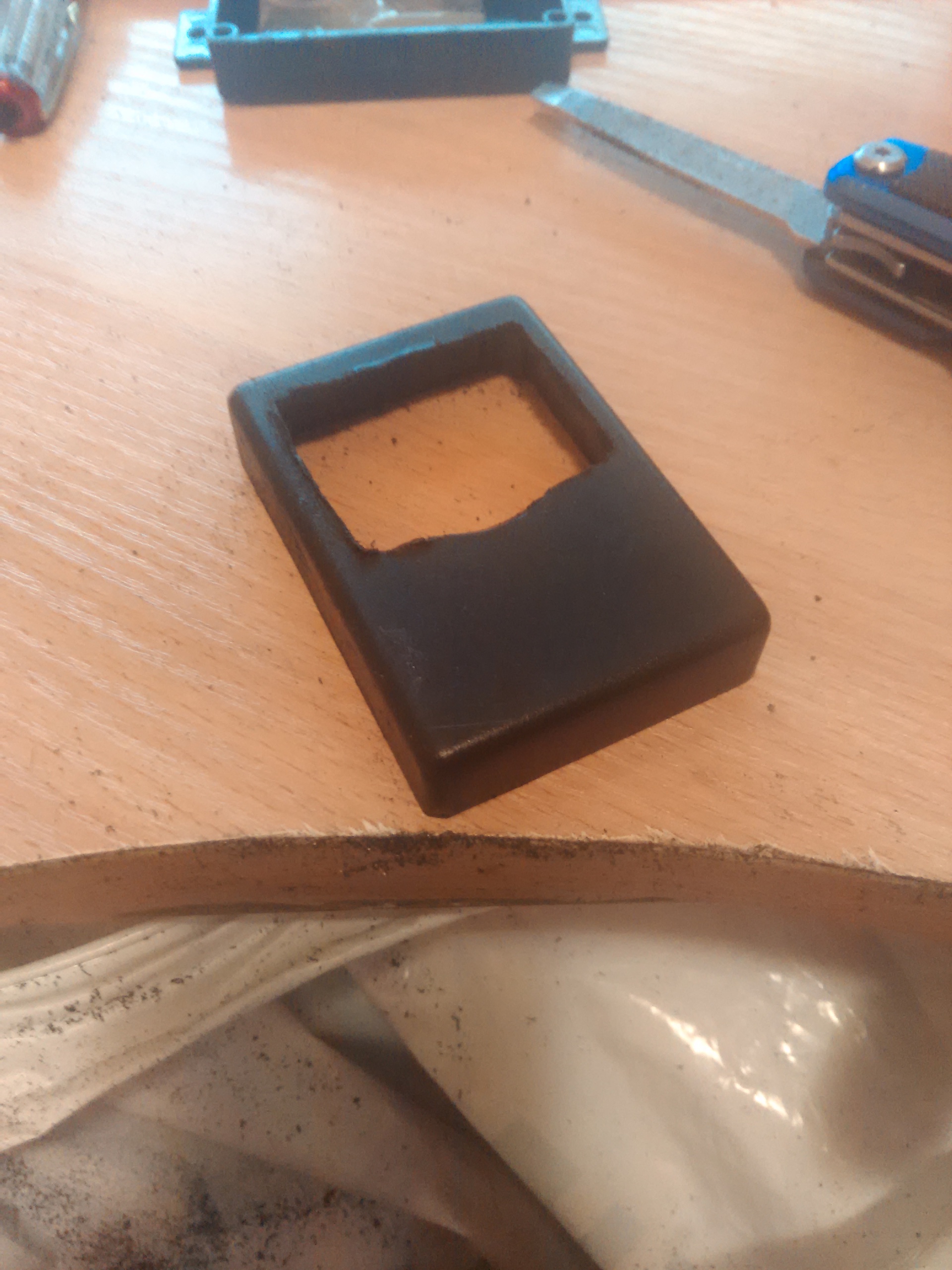
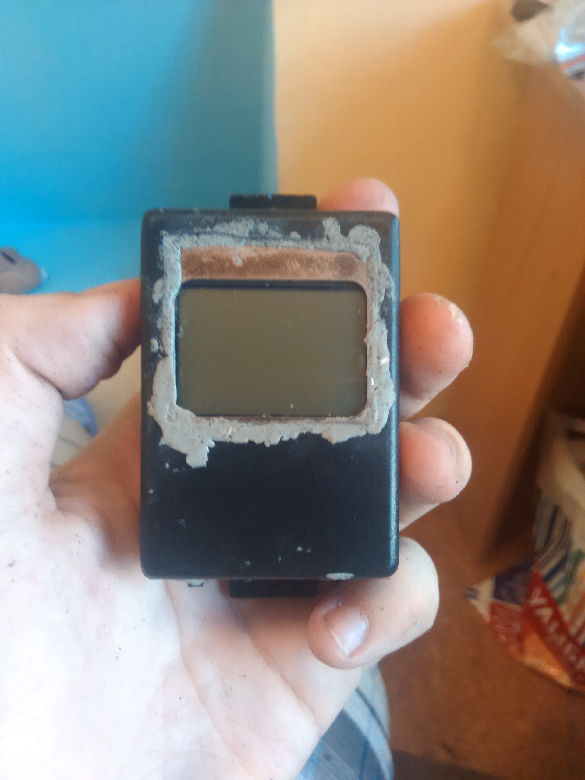
The device worked, but of course I wanted to give a complete look. It just so happened that all I could find was just one building, and it turned out to be “narrow.”
A couple of millimeters
I had to change the location of the components: everything got into the case, but the final size became larger. In the process of re-soldering, I had to replace the Arduino Nano and the SD module: I own the soldering iron so-so, and part of the conclusions simply made it unusable.
Dimensions: 72x50x28mm
The file also had to work ...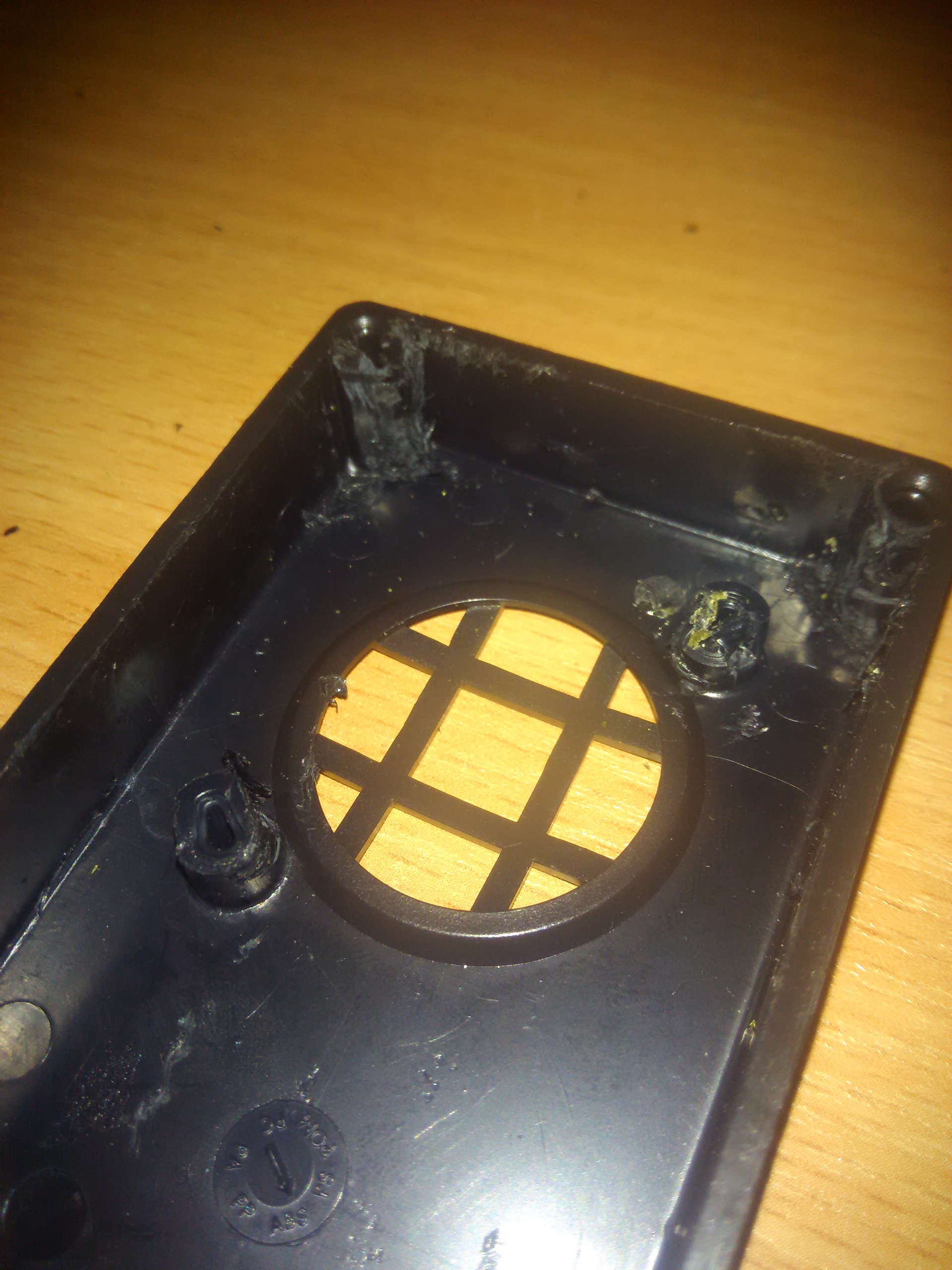

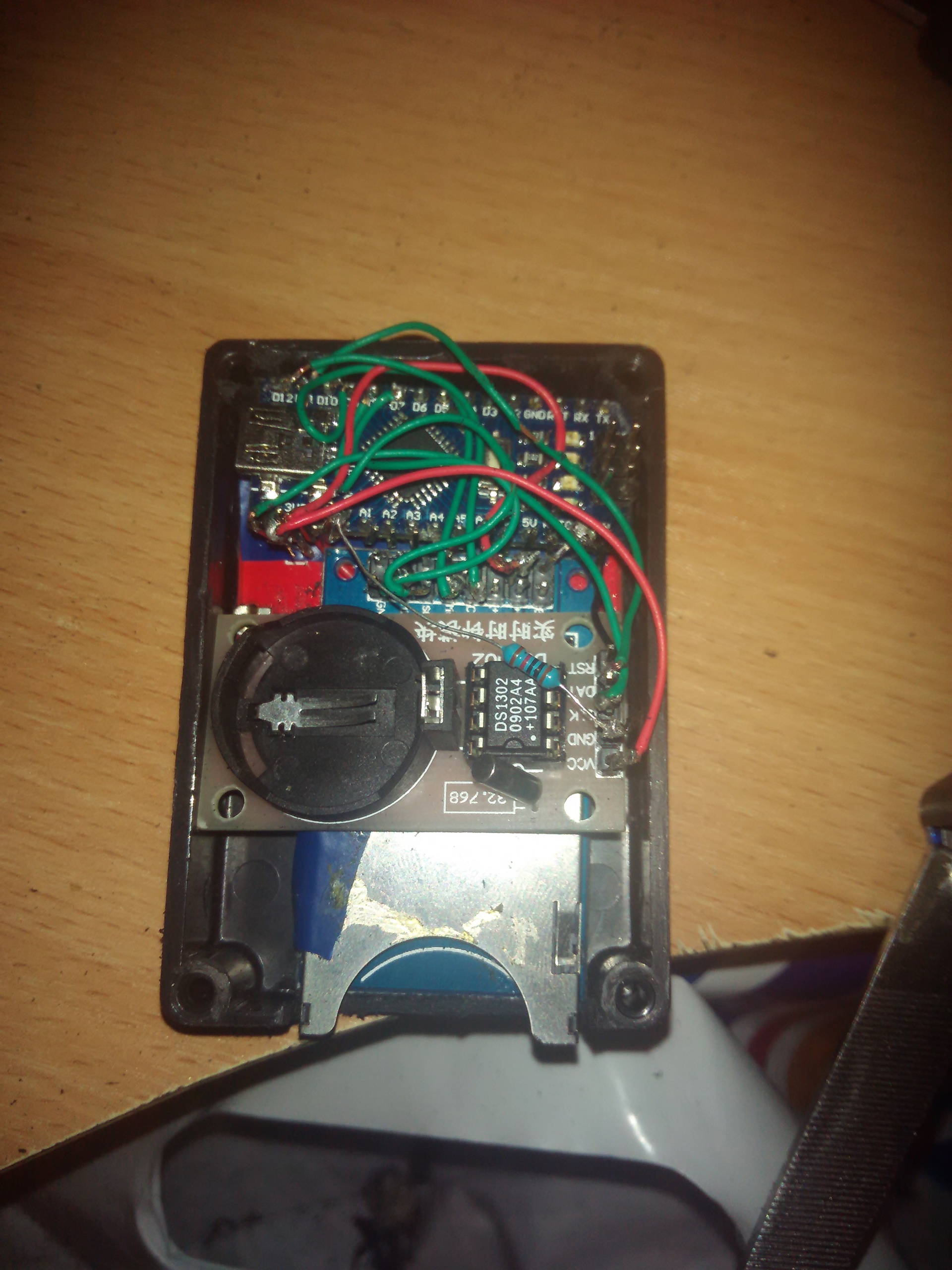

After I checked the performance of all modules, I decided to fix them with epoxy glue for greater resistance to shaking.
In this form, I will not leave the computer. Grinding and painting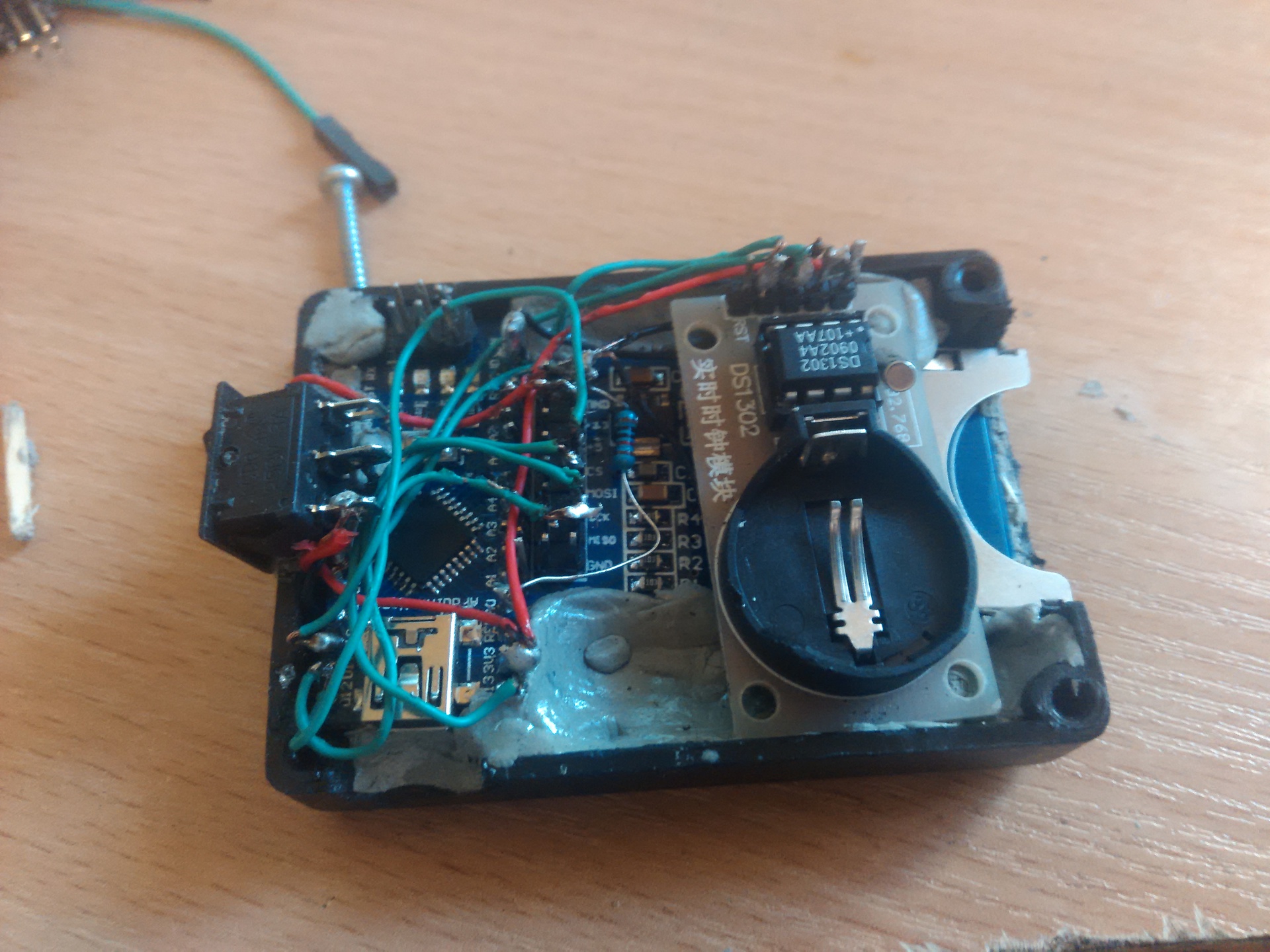

My haste played a cruel joke: I didn’t fix the wires under the screen well enough and one of them started to interfere (in fact, this affects the “contrast” parameter).
It is treated by simple tapping, as in old TVs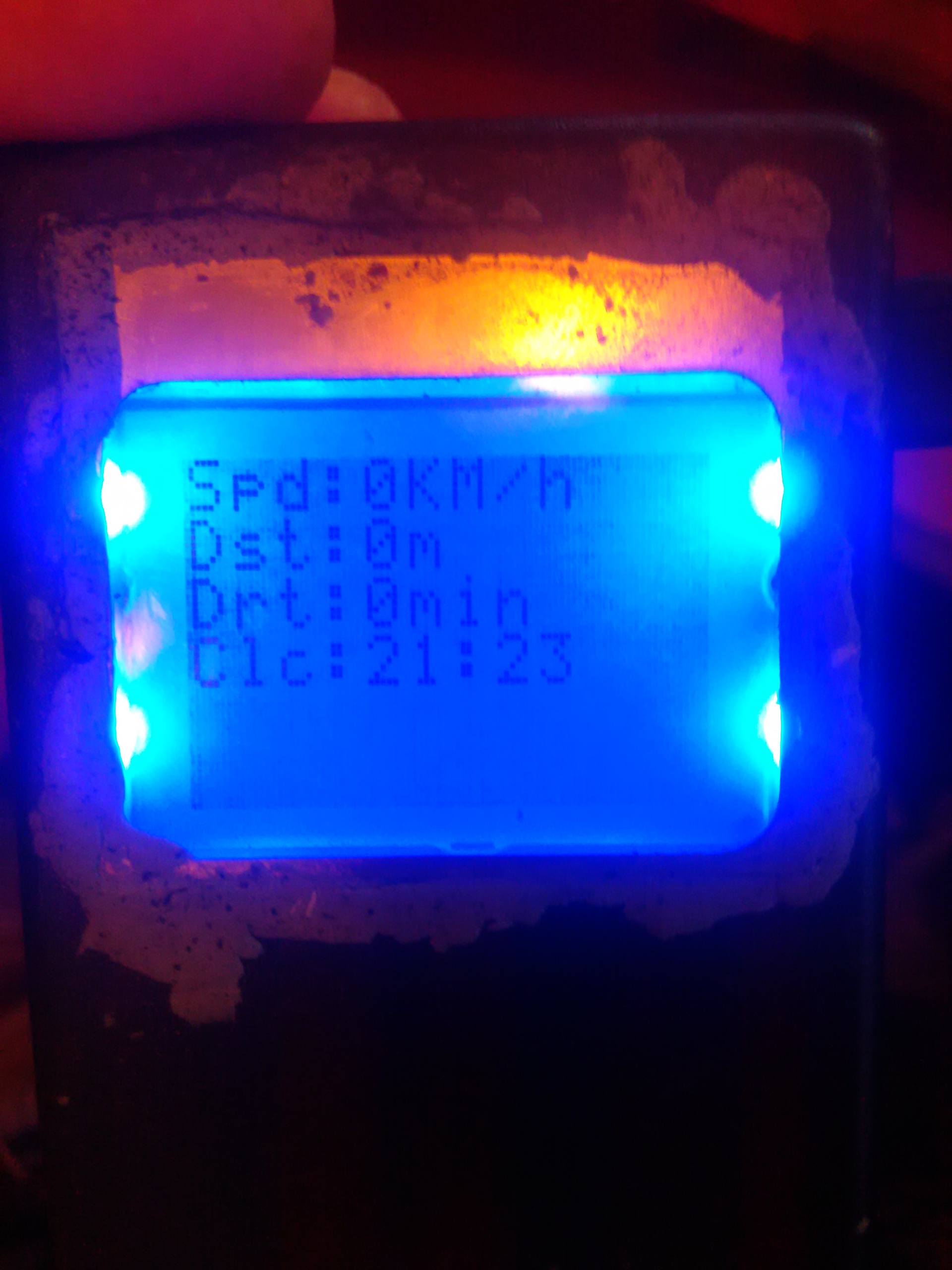

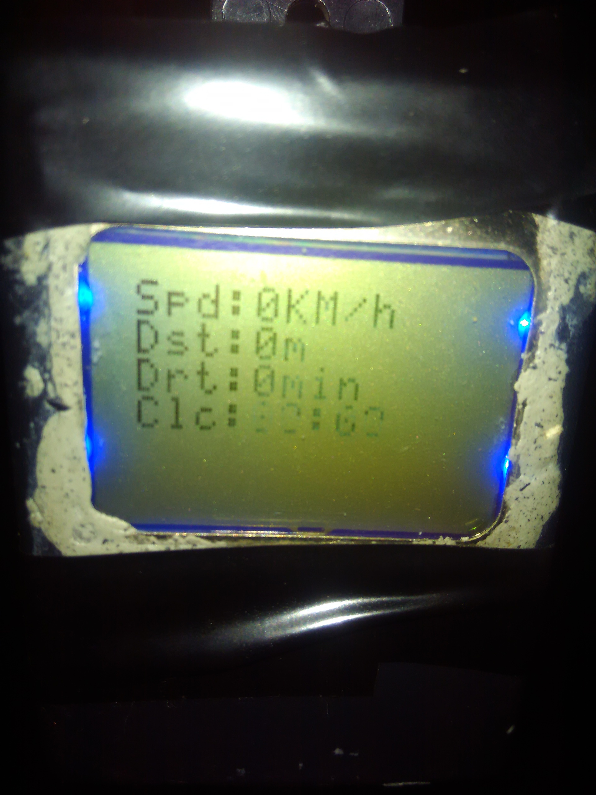
A couple more corrections in the code, and the interface was reduced to the final (for the time being) view.
Device Assembly
- Speed (km / h)
- Odometer (Distance in meters)
- Travel time (In minutes)
- Current time (Moscow time)
The trouble was presented by the clock: one of the contacts went away, and time began to ride (as if I had confused RST and CLK). But what is most interesting - after the trip the clock returned to normal.
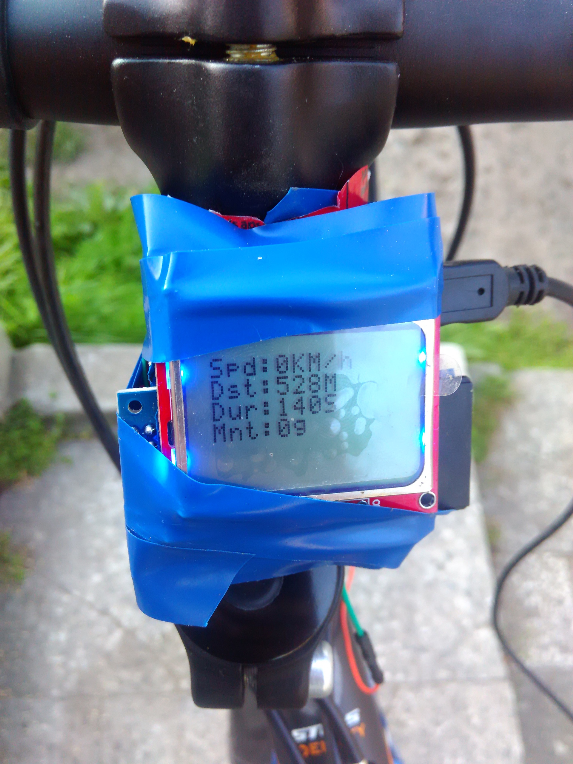
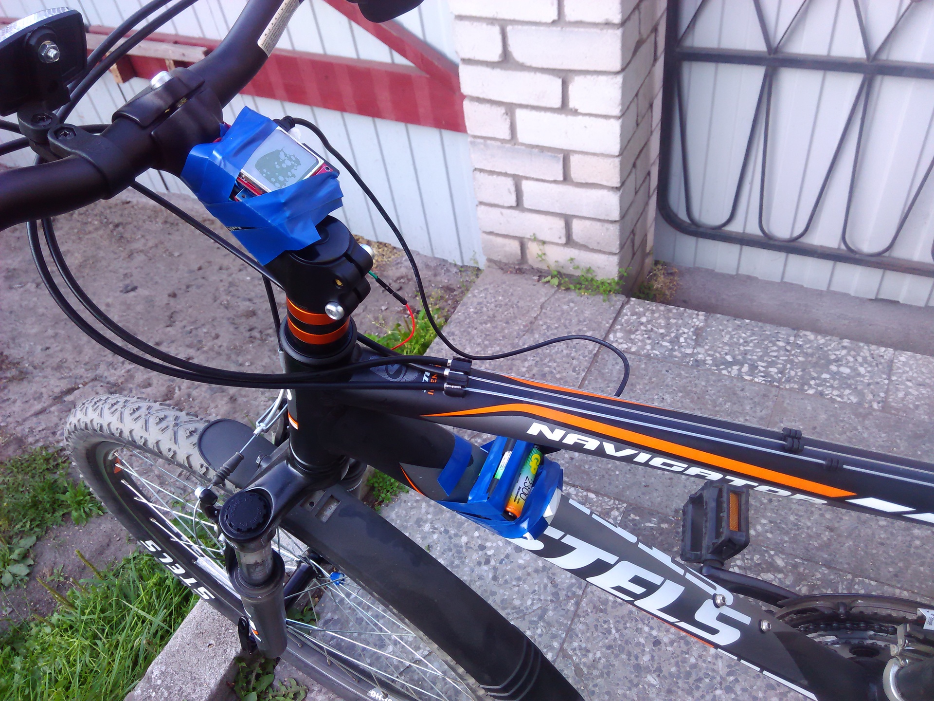
Perhaps the claim can be made to the angle of attachment: during the trip it is inconvenient to look.
Almost vertical fasteners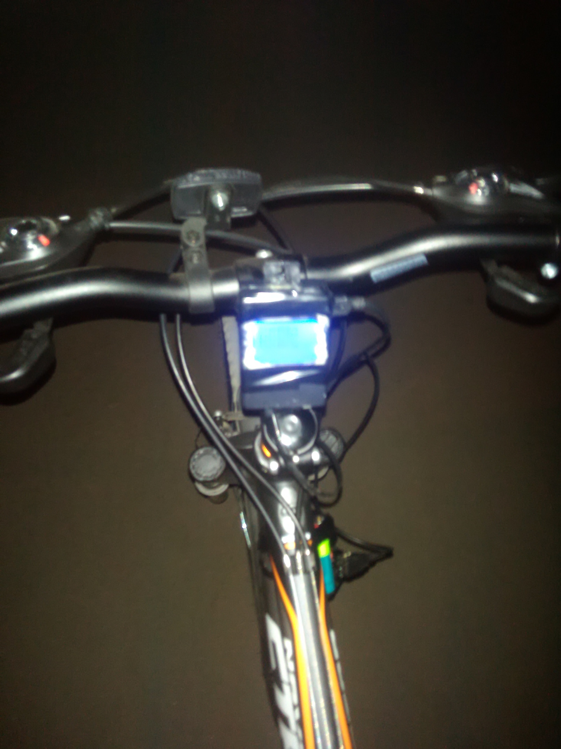
Yes, and the method of fastening with electrical tape is not ideal, but I could not find a separate bracket for bicycle gadgets. Although, from China, a spider is coming to me. I think that it is quite suitable for solving this problem.
Final option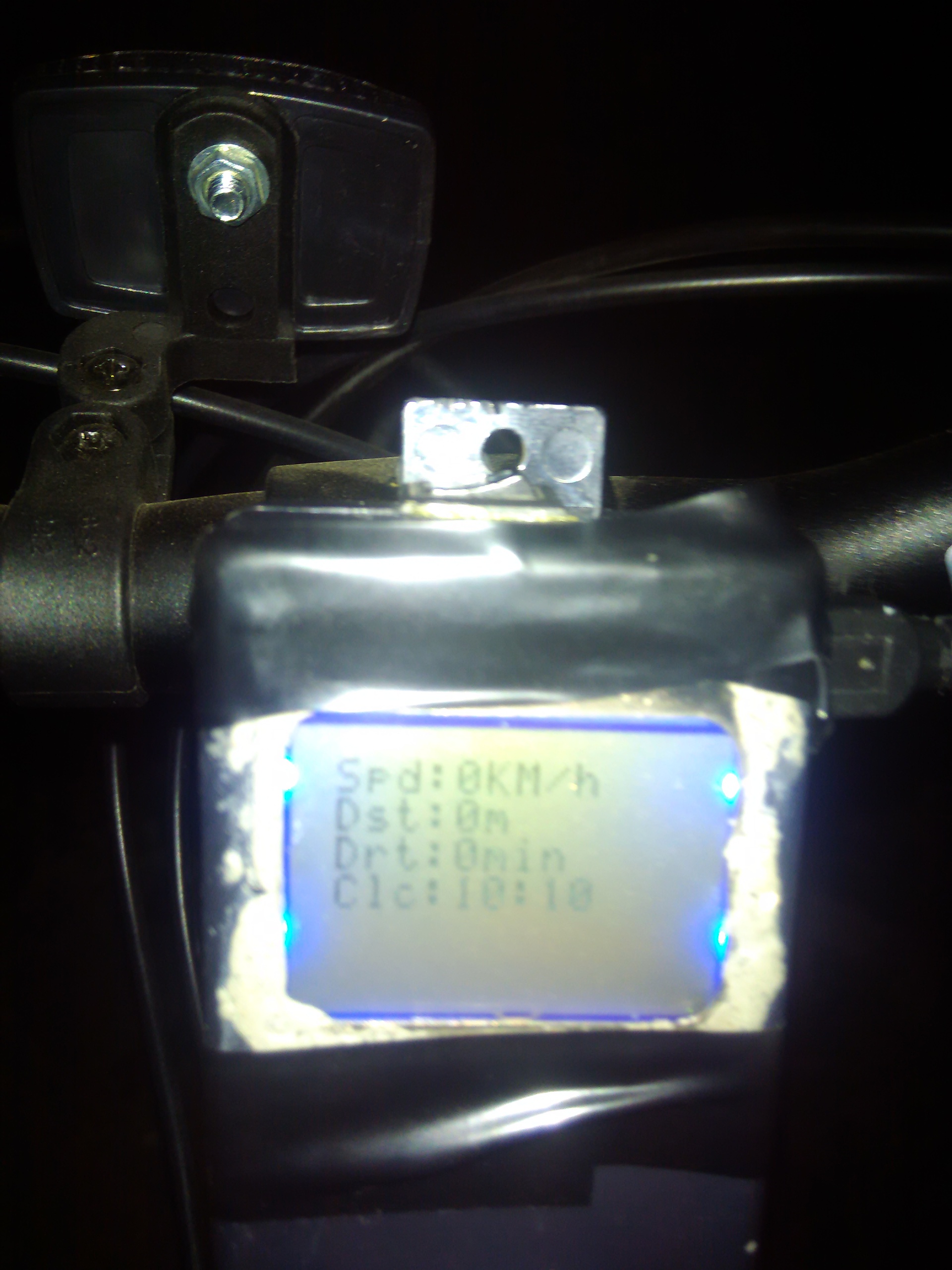


Cost of
- Housing BOX-G020 - 115r
- Epoxyline - 95r
- Batteries - 60r
- Arduino Nano - 120r
- Nokia LCD 5110 - 102r
- Black electrical tape - 40r
- SD module - 187r
- DS1302 - 70r
- Cases for batteries - 120r
- Wires and Resistors - 80p
- Reed switch + magnet - 82r
Total: ~ 1100r
Related Links
Results
I got a little more experience with Arduino and assembling small working devices. I spent a few hours of fun, but most importantly, I now have a working bike computer. There are plans to write normal saving / loading of “global” data onto a memory card and add a button to display “global” statistics. To control external devices, I have six analog ports (three buttons & three thyristors) and somewhere I lost one digital, for example, for a rangefinder (parking sensors) or a thermometer. I would very much like to solve the power problem, because five AA batteries on the bicycle frame do not look very good.
The cat who helped test the bike
Sketch code
#include <SD.h> #include <DS1302.h> //Function: This procedure applies to the Arduino driver NOKIA 5110 LCD. //Time:September 4,2012 #define PIN_SCE 3 #define PIN_RESET 2 #define PIN_DC 4 #define PIN_SDIN 5 #define PIN_SCLK 6 #define reed A0// #define LCD_C LOW #define LCD_D HIGH int count=0; char dat[4]; char disp_tab[]={ '0','1','2','3','4','5','6','7','8','9'}; #define LCD_X 84 #define LCD_Y 48 const int chipSelect = 10; static const byte ASCII[][5] = { { 0x00, 0x00, 0x00, 0x00, 0x00 } // 20 ,{ 0x00, 0x00, 0x5f, 0x00, 0x00 } // 21 ! ,{ 0x00, 0x07, 0x00, 0x07, 0x00 } // 22 " ,{ 0x14, 0x7f, 0x14, 0x7f, 0x14 } // 23 # ,{ 0x24, 0x2a, 0x7f, 0x2a, 0x12 } // 24 $ ,{ 0x23, 0x13, 0x08, 0x64, 0x62 } // 25 % ,{ 0x36, 0x49, 0x55, 0x22, 0x50 } // 26 & ,{ 0x00, 0x05, 0x03, 0x00, 0x00 } // 27 ' ,{ 0x00, 0x1c, 0x22, 0x41, 0x00 } // 28 ( ,{ 0x00, 0x41, 0x22, 0x1c, 0x00 } // 29 ) ,{ 0x14, 0x08, 0x3e, 0x08, 0x14 } // 2a * ,{ 0x08, 0x08, 0x3e, 0x08, 0x08 } // 2b + ,{ 0x00, 0x50, 0x30, 0x00, 0x00 } // 2c , ,{ 0x08, 0x08, 0x08, 0x08, 0x08 } // 2d - ,{ 0x00, 0x60, 0x60, 0x00, 0x00 } // 2e . ,{ 0x20, 0x10, 0x08, 0x04, 0x02 } // 2f / ,{ 0x3e, 0x51, 0x49, 0x45, 0x3e } // 30 0 ,{ 0x00, 0x42, 0x7f, 0x40, 0x00 } // 31 1 ,{ 0x42, 0x61, 0x51, 0x49, 0x46 } // 32 2 ,{ 0x21, 0x41, 0x45, 0x4b, 0x31 } // 33 3 ,{ 0x18, 0x14, 0x12, 0x7f, 0x10 } // 34 4 ,{ 0x27, 0x45, 0x45, 0x45, 0x39 } // 35 5 ,{ 0x3c, 0x4a, 0x49, 0x49, 0x30 } // 36 6 ,{ 0x01, 0x71, 0x09, 0x05, 0x03 } // 37 7 ,{ 0x36, 0x49, 0x49, 0x49, 0x36 } // 38 8 ,{ 0x06, 0x49, 0x49, 0x29, 0x1e } // 39 9 ,{ 0x00, 0x36, 0x36, 0x00, 0x00 } // 3a : ,{ 0x00, 0x56, 0x36, 0x00, 0x00 } // 3b ; ,{ 0x08, 0x14, 0x22, 0x41, 0x00 } // 3c < ,{ 0x14, 0x14, 0x14, 0x14, 0x14 } // 3d = ,{ 0x00, 0x41, 0x22, 0x14, 0x08 } // 3e > ,{ 0x02, 0x01, 0x51, 0x09, 0x06 } // 3f ? ,{ 0x32, 0x49, 0x79, 0x41, 0x3e } // 40 @ ,{ 0x7e, 0x11, 0x11, 0x11, 0x7e } // 41 A ,{ 0x7f, 0x49, 0x49, 0x49, 0x36 } // 42 B ,{ 0x3e, 0x41, 0x41, 0x41, 0x22 } // 43 C ,{ 0x7f, 0x41, 0x41, 0x22, 0x1c } // 44 D ,{ 0x7f, 0x49, 0x49, 0x49, 0x41 } // 45 E ,{ 0x7f, 0x09, 0x09, 0x09, 0x01 } // 46 F ,{ 0x3e, 0x41, 0x49, 0x49, 0x7a } // 47 G ,{ 0x7f, 0x08, 0x08, 0x08, 0x7f } // 48 H ,{ 0x00, 0x41, 0x7f, 0x41, 0x00 } // 49 I ,{ 0x20, 0x40, 0x41, 0x3f, 0x01 } // 4a J ,{ 0x7f, 0x08, 0x14, 0x22, 0x41 } // 4b K ,{ 0x7f, 0x40, 0x40, 0x40, 0x40 } // 4c L ,{ 0x7f, 0x02, 0x0c, 0x02, 0x7f } // 4d M ,{ 0x7f, 0x04, 0x08, 0x10, 0x7f } // 4e N ,{ 0x3e, 0x41, 0x41, 0x41, 0x3e } // 4f O ,{ 0x7f, 0x09, 0x09, 0x09, 0x06 } // 50 P ,{ 0x3e, 0x41, 0x51, 0x21, 0x5e } // 51 Q ,{ 0x7f, 0x09, 0x19, 0x29, 0x46 } // 52 R ,{ 0x46, 0x49, 0x49, 0x49, 0x31 } // 53 S ,{ 0x01, 0x01, 0x7f, 0x01, 0x01 } // 54 T ,{ 0x3f, 0x40, 0x40, 0x40, 0x3f } // 55 U ,{ 0x1f, 0x20, 0x40, 0x20, 0x1f } // 56 V ,{ 0x3f, 0x40, 0x38, 0x40, 0x3f } // 57 W ,{ 0x63, 0x14, 0x08, 0x14, 0x63 } // 58 X ,{ 0x07, 0x08, 0x70, 0x08, 0x07 } // 59 Y ,{ 0x61, 0x51, 0x49, 0x45, 0x43 } // 5a Z ,{ 0x00, 0x7f, 0x41, 0x41, 0x00 } // 5b [ ,{ 0x02, 0x04, 0x08, 0x10, 0x20 } // 5c ¥ ,{ 0x00, 0x41, 0x41, 0x7f, 0x00 } // 5d ] ,{ 0x04, 0x02, 0x01, 0x02, 0x04 } // 5e ^ ,{ 0x40, 0x40, 0x40, 0x40, 0x40 } // 5f _ ,{ 0x00, 0x01, 0x02, 0x04, 0x00 } // 60 ` ,{ 0x20, 0x54, 0x54, 0x54, 0x78 } // 61 a ,{ 0x7f, 0x48, 0x44, 0x44, 0x38 } // 62 b ,{ 0x38, 0x44, 0x44, 0x44, 0x20 } // 63 c ,{ 0x38, 0x44, 0x44, 0x48, 0x7f } // 64 d ,{ 0x38, 0x54, 0x54, 0x54, 0x18 } // 65 e ,{ 0x08, 0x7e, 0x09, 0x01, 0x02 } // 66 f ,{ 0x0c, 0x52, 0x52, 0x52, 0x3e } // 67 g ,{ 0x7f, 0x08, 0x04, 0x04, 0x78 } // 68 h ,{ 0x00, 0x44, 0x7d, 0x40, 0x00 } // 69 i ,{ 0x20, 0x40, 0x44, 0x3d, 0x00 } // 6a j ,{ 0x7f, 0x10, 0x28, 0x44, 0x00 } // 6b k ,{ 0x00, 0x41, 0x7f, 0x40, 0x00 } // 6c l ,{ 0x7c, 0x04, 0x18, 0x04, 0x78 } // 6d m ,{ 0x7c, 0x08, 0x04, 0x04, 0x78 } // 6e n ,{ 0x38, 0x44, 0x44, 0x44, 0x38 } // 6f o ,{ 0x7c, 0x14, 0x14, 0x14, 0x08 } // 70 p ,{ 0x08, 0x14, 0x14, 0x18, 0x7c } // 71 q ,{ 0x7c, 0x08, 0x04, 0x04, 0x08 } // 72 r ,{ 0x48, 0x54, 0x54, 0x54, 0x20 } // 73 s ,{ 0x04, 0x3f, 0x44, 0x40, 0x20 } // 74 t ,{ 0x3c, 0x40, 0x40, 0x20, 0x7c } // 75 u ,{ 0x1c, 0x20, 0x40, 0x20, 0x1c } // 76 v ,{ 0x3c, 0x40, 0x30, 0x40, 0x3c } // 77 w ,{ 0x44, 0x28, 0x10, 0x28, 0x44 } // 78 x ,{ 0x0c, 0x50, 0x50, 0x50, 0x3c } // 79 y ,{ 0x44, 0x64, 0x54, 0x4c, 0x44 } // 7a z ,{ 0x00, 0x08, 0x36, 0x41, 0x00 } // 7b { ,{ 0x00, 0x00, 0x7f, 0x00, 0x00 } // 7c | ,{ 0x00, 0x41, 0x36, 0x08, 0x00 } // 7d } ,{ 0x10, 0x08, 0x08, 0x10, 0x08 } // 7e ← ,{ 0x78, 0x46, 0x41, 0x46, 0x78 } // 7f → }; void LcdCharacter(char character) { LcdWrite(LCD_D, 0x00); for (int index = 0; index < 5; index++) { LcdWrite(LCD_D, ASCII[character - 0x20][index]); } LcdWrite(LCD_D, 0x00); } void LcdClear(void) { for (int index = 0; index < LCD_X * LCD_Y / 8; index++) { LcdWrite(LCD_D, 0x00); } } void LcdInitialise(void) { pinMode(PIN_SCE, OUTPUT); pinMode(PIN_RESET, OUTPUT); pinMode(PIN_DC, OUTPUT); pinMode(PIN_SDIN, OUTPUT); pinMode(PIN_SCLK, OUTPUT); digitalWrite(PIN_RESET, LOW); digitalWrite(PIN_RESET, HIGH); LcdWrite(LCD_C, 0x21 ); // LCD Extended Commands. LcdWrite(LCD_C, 0xB1 ); // Set LCD Vop (Contrast). LcdWrite(LCD_C, 0x04 ); // Set Temp coefficent. //0x04 LcdWrite(LCD_C, 0x14 ); // LCD bias mode 1:48. //0x13 LcdWrite(LCD_C, 0x0C ); // LCD in normal mode. LcdWrite(LCD_C, 0x20 ); LcdWrite(LCD_C, 0x0C ); } void LcdString(char *characters) { while (*characters) { LcdCharacter(*characters++); } } void LcdWrite(byte dc, byte data) { digitalWrite(PIN_DC, dc); digitalWrite(PIN_SCE, LOW); shiftOut(PIN_SDIN, PIN_SCLK, MSBFIRST, data); digitalWrite(PIN_SCE, HIGH); } void gotoXY(int x, int y) { LcdWrite( 0, 0x80 | x); // Column. LcdWrite( 0, 0x40 | y); // Row. } void dispcountt(int count) { LcdCharacter(disp_tab[count/10000]); LcdCharacter(disp_tab[count/1000%10]); LcdCharacter(disp_tab[count/100%10]); LcdCharacter(disp_tab[count%100/10]); LcdCharacter(disp_tab[count%10]); } //storage variables float radius = 13.5;// . 26 , 13.5 () boolean reedVal; long timer = 0;// float kmh = 0.00;// / float circumference; float distance = 0;// long totalDistance = 0;// long totalTime = 0;// float distanceBuffer = 0;// long timeBuffer = 0;// float deltaD;// boolean moving = false; // - long time = 0;// long lastTime = millis(); long duration = 0; DS1302 rtc(9, 8, 7); int maxReedCounter = 100;// int reedCounter; void setup(void) { rtc.halt(false); rtc.writeProtect(false); pinMode(10, OUTPUT);// reedCounter = maxReedCounter; deltaD = 2*3.415926535*radius*0.025;// circumference = 2*3.14*radius;// , ( ) pinMode(A0, INPUT); // TIMER SETUP- the timer interrupt allows preceise timed measurements of the reed switch //for mor info about configuration of arduino timers see http://arduino.cc/playground/Code/Timer1 cli();//stop interrupts //set timer1 interrupt at 1kHz TCCR1A = 0;// set entire TCCR1A register to 0 TCCR1B = 0;// same for TCCR1B TCNT1 = 0; // set timer count for 1khz increments OCR1A = 1999;// = (1/1000) / ((1/(16*10^6))*8) - 1 // turn on CTC mode TCCR1B |= (1 << WGM12); // Set CS11 bit for 8 prescaler TCCR1B |= (1 << CS11); // enable timer compare interrupt TIMSK1 |= (1 << OCIE1A); sei();//allow interrupts //END TIMER SETUP LcdInitialise(); LcdClear(); LcdString("Initializing SD card..."); pinMode(10, OUTPUT); gotoXY(0, 1); if (!SD.begin(chipSelect)) { LcdString("Card failed, or not present"); }else{ LcdString("Card initialized."); File logFile = SD.open("logfile.txt"); if (logFile) { gotoXY(0, 2); LcdString("reading file"); while (logFile.available()) { totalDistance = logFile.parseInt(); totalTime = logFile.parseInt(); } } else { gotoXY(0, 2); LcdString("error read file"); } } LcdClear(); gotoXY(0, 0); LcdString("Spd:");// / gotoXY(0, 1); LcdString("Dst:");// gotoXY(0, 2); LcdString("Drt:");// gotoXY(0, 3); LcdString("Clc:");// } ISR(TIMER1_COMPA_vect) {// 1 if(analogRead(reed) >= 680 && analogRead(reed) <= 742){// reedVal = true; }else{ reedVal = false; } if (reedVal){// if (timer > 110){ moving = true; } if (reedCounter == 0){// if(moving){ kmh = (56.8*float(circumference))/float(timer)*1.61;// distance += deltaD; distanceBuffer } reedCounter = maxReedCounter;// reedCounter timer = 0;// } else{ if (reedCounter > 0){// reedCounter -= 1;// reedCounter } } }else{// if (reedCounter > 0){// reedCounter -= 1;// reedCounter } } if (timer > 2000){ kmh = 0;// , . moving = false; }else{ timer += 1;// } } void updateDisplay(){ for(int i = 0; i<=3; i++){ gotoXY(28, i); LcdString(" "); } char Sensor1CharMsg[8]; gotoXY(28, 0); if(moving){ String Sensor1String((int)(kmh), DEC); Sensor1String.toCharArray(Sensor1CharMsg,(Sensor1String.length()+1)); LcdString(Sensor1CharMsg); }else{ LcdString("0"); } LcdString("KM/h"); gotoXY(28, 1); String Sensor1String2((int)(distance), DEC); Sensor1String2.toCharArray(Sensor1CharMsg,(Sensor1String2.length()+1)); LcdString(Sensor1CharMsg); LcdString("m"); gotoXY(28, 2); String Sensor1String3((int)(duration/60), DEC); Sensor1String3.toCharArray(Sensor1CharMsg,(Sensor1String3.length()+1)); LcdString(Sensor1CharMsg); LcdString("min"); gotoXY(28, 3); String Sensor1String4(rtc.getTimeStr(FORMAT_SHORT)); Sensor1String4.toCharArray(Sensor1CharMsg,(Sensor1String4.length()+1)); LcdString(Sensor1CharMsg); } void loop(void) { if (reedVal){// if (timer <= 110){ moving = false;// , }else{ moving = true; } } updateDisplay(); saveData(); if (moving){ int d = (int)((millis()-lastTime)/1000) timeBuffer += d; duration += d; } lastTime = millis(); delay(1000); } void saveData(){ while(timeBuffer>=60){ timeBuffer-=60; totalTime++; } while(distanceBuffer>=11){ distanceBuffer-=11; totalDistance+=11; } } Source: https://habr.com/ru/post/231113/
All Articles