We make a desktop device for the manufacture of printed circuit boards in one click
Once again, washing the shell of red ferric chloride stains, after etching the board, I thought it was time to automate this process. So I began to make a device for the manufacture of boards, which can now be used to create the simplest electronics.

Below I will talk about how to make this device.
The basic process of manufacturing a printed circuit board by the subtractive method is that unnecessary foil areas are removed on the foil material.
')
Today, most electronics engineers use technology such as laser-iron for home-made circuit boards. This method involves removing unnecessary parts of the foil using a chemical solution that eats away the foil in unwanted places. The first experiments with LUT several years ago showed me that this technology is full of little things, sometimes completely interfering with the achievement of an acceptable result. There is both the preparation of the board surface, and the choice of paper or other material for printing, and the temperature combined with the heating time, as well as the peculiarities of washing the remnants of the glossy layer. You also have to work with chemistry, and this is not always convenient and useful at home.
I wanted to put on the table some device into which you can send the board's source code to the printer, press a button, and after some time get the finished board.
A little googling you can see that people, starting from the 70s of the last century, began to develop desktop devices for the manufacture of printed circuit boards. First of all, there were milling machines for printed circuit boards, which cut out the tracks on the foil textolyte with a special cutter. The essence of the technology lies in the fact that at high revolutions a mill mounted on a rigid and precise coordinate table with CNC cuts a layer of foil in the right places.
The desire to immediately buy a specialized machine passed after studying the prices from the supplier. I, like most hobbyists, are not ready to lay out such money for the device. Therefore, it was decided to make the machine yourself.
It is clear that the device should consist of a coordinate table that moves the cutting tool to the desired point and the cutting device itself.
On the Internet, there are enough examples of how to make a coordinate table for every taste. For example, the same RepRap cope with this task (with corrections for accuracy).
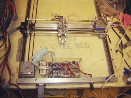
From one of my previous hobby projects to create a plotter, I still had a homemade coordinate table. Therefore, the main task was to create a cutting tool.
A logical step could be to equip the plotter with a miniature engraver like Dremel. But the problem is that the plotter, which can be cheaply assembled at home, is difficult to do with the necessary rigidity, parallelism of its plane to the textolite plane (even the textolite itself can be curved). As a result, it would not have been possible to cut a board with less good quality. In addition, the fact that the cutter becomes dull with time and loses its cutting properties is not in favor of the use of milling. It would be great if copper could be removed from the PCB surface in a non-contact manner.
Already there are laser machines of the German manufacturer LPKF, in which the foil is simply evaporated by a powerful semiconductor laser in the infrared range. Machines are distinguished by accuracy and processing speed, but their price is even higher than that of milling, and it is not yet an easy task to assemble such a material from materials accessible to everyone and somehow cheapen it.
From the above, I have formed some requirements for the desired device:
So I began to think about a possible alternative to a laser in the field of contactless removal of copper from a PCB. And I came across an electric spark treatment method , which has long been used in metal processing for the manufacture of precision metal parts.
With this method, the metal is removed by electrical discharges, which evaporate and spray it from the surface of the workpiece. Thus, craters are formed, the size of which depends on the discharge energy, its duration and, of course, the type of material of the workpiece. In the simplest form, electric erosion began to be used in the 40s of the 20th century for punching holes in metal parts. Unlike traditional machining, holes could be made of almost any shape. Currently, this method is actively used in metalworking and has spawned a whole series of types of machine tools.
An obligatory part of such machines is the current pulse generator, the system for feeding and moving the electrode — namely, an electrode (usually copper, brass, or graphite) is a working tool of such a machine. The simplest current pulse generator is a simple capacitor of the desired rating, connected to a constant voltage source through a current-limiting resistor. In this case, the capacitance and voltage determine the discharge energy, which in turn determines the size of the craters, and hence the processing purity. However, there is one significant nuance - the voltage on the capacitor in the operating mode is determined by the breakdown voltage. The latter almost linearly depends on the gap between the electrode and the workpiece.
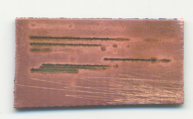
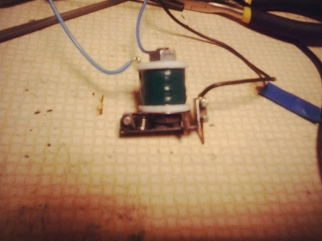
During the evening, a prototype erosion tool was made, which is a solenoid, to the anchor of which a copper wire is attached. The solenoid provided wire vibration and contact interruption. The LATR was used as a power source: the rectified current charged the capacitor, and the alternating one fed the solenoid. This design was also fixed in the plotter pen holder. In general, the result met the expectations, and the head left solid stripes on the foil with torn edges.
The method clearly had the right to life, but it was necessary to solve one problem - to compensate for the consumption of wire, which is spent during operation. To do this, it was necessary to create a feed mechanism and a control unit for it.
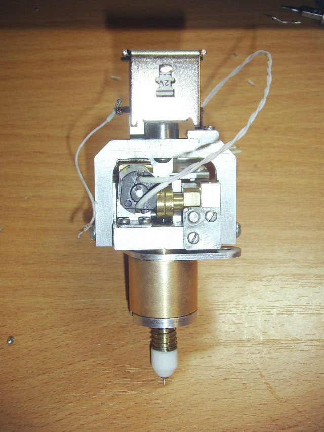
After that, I began to spend all my free time in one of the hackspaces of our city, where there are metalworking machines. Continued attempts to make an acceptable cutting device began. The erosion head consisted of a pair of stem-bushing, providing vertical vibration, a return spring and a broaching mechanism. To control the solenoid, it was necessary to manufacture a simple circuit consisting of a pulse generator of a given length on the NE555, a MOSFET transistor and an inductive current sensor. Initially it was supposed to use self-oscillation mode, that is, to give a pulse to the key immediately after the current pulse. The oscillation frequency depends on the size of the gap and the drive is controlled according to the measurement of the period of self-oscillations. However, a stable self-oscillation mode was possible in the range of amplitudes of oscillations of the head, which was less than half of the maximum. Therefore, I decided to use a fixed frequency of oscillations generated by hardware PWM. In this case, the state of the gap between the wire and the board can be judged by the time between the end of the opening pulse and the first current pulse. For greater stability during operation and improvement of frequency characteristics, the solenoid was fixed above the wire pulling mechanism, and the anchor was placed on the duralumin bracket. After these improvements, it was possible to achieve stable operation at frequencies up to 35 Hz.
Having fixed the cutting head on the plotter, I began experiments on cutting through the insulating tracks on the printed circuit boards. The first result is achieved and the head more or less steadily provides a continuous cut. Here is a video showing what happened:
The fundamental possibility of making boards using electric spark machining is confirmed. In the near future, we are going to improve accuracy, increase processing speed and cleanliness of the cut, as well as lay out part of the developments in open access. I also plan to adapt the module for use with RepRap. I will welcome ideas and comments in the comments.
Below I will talk about how to make this device.
The basic process of manufacturing a printed circuit board by the subtractive method is that unnecessary foil areas are removed on the foil material.
')
Today, most electronics engineers use technology such as laser-iron for home-made circuit boards. This method involves removing unnecessary parts of the foil using a chemical solution that eats away the foil in unwanted places. The first experiments with LUT several years ago showed me that this technology is full of little things, sometimes completely interfering with the achievement of an acceptable result. There is both the preparation of the board surface, and the choice of paper or other material for printing, and the temperature combined with the heating time, as well as the peculiarities of washing the remnants of the glossy layer. You also have to work with chemistry, and this is not always convenient and useful at home.
I wanted to put on the table some device into which you can send the board's source code to the printer, press a button, and after some time get the finished board.
A little googling you can see that people, starting from the 70s of the last century, began to develop desktop devices for the manufacture of printed circuit boards. First of all, there were milling machines for printed circuit boards, which cut out the tracks on the foil textolyte with a special cutter. The essence of the technology lies in the fact that at high revolutions a mill mounted on a rigid and precise coordinate table with CNC cuts a layer of foil in the right places.
The desire to immediately buy a specialized machine passed after studying the prices from the supplier. I, like most hobbyists, are not ready to lay out such money for the device. Therefore, it was decided to make the machine yourself.
It is clear that the device should consist of a coordinate table that moves the cutting tool to the desired point and the cutting device itself.
On the Internet, there are enough examples of how to make a coordinate table for every taste. For example, the same RepRap cope with this task (with corrections for accuracy).
From one of my previous hobby projects to create a plotter, I still had a homemade coordinate table. Therefore, the main task was to create a cutting tool.
A logical step could be to equip the plotter with a miniature engraver like Dremel. But the problem is that the plotter, which can be cheaply assembled at home, is difficult to do with the necessary rigidity, parallelism of its plane to the textolite plane (even the textolite itself can be curved). As a result, it would not have been possible to cut a board with less good quality. In addition, the fact that the cutter becomes dull with time and loses its cutting properties is not in favor of the use of milling. It would be great if copper could be removed from the PCB surface in a non-contact manner.
Already there are laser machines of the German manufacturer LPKF, in which the foil is simply evaporated by a powerful semiconductor laser in the infrared range. Machines are distinguished by accuracy and processing speed, but their price is even higher than that of milling, and it is not yet an easy task to assemble such a material from materials accessible to everyone and somehow cheapen it.
From the above, I have formed some requirements for the desired device:
- The price is comparable to the cost of an average home 3D printer
- Contactless copper removal
- Ability to assemble the device from the available components yourself at home
So I began to think about a possible alternative to a laser in the field of contactless removal of copper from a PCB. And I came across an electric spark treatment method , which has long been used in metal processing for the manufacture of precision metal parts.
With this method, the metal is removed by electrical discharges, which evaporate and spray it from the surface of the workpiece. Thus, craters are formed, the size of which depends on the discharge energy, its duration and, of course, the type of material of the workpiece. In the simplest form, electric erosion began to be used in the 40s of the 20th century for punching holes in metal parts. Unlike traditional machining, holes could be made of almost any shape. Currently, this method is actively used in metalworking and has spawned a whole series of types of machine tools.
An obligatory part of such machines is the current pulse generator, the system for feeding and moving the electrode — namely, an electrode (usually copper, brass, or graphite) is a working tool of such a machine. The simplest current pulse generator is a simple capacitor of the desired rating, connected to a constant voltage source through a current-limiting resistor. In this case, the capacitance and voltage determine the discharge energy, which in turn determines the size of the craters, and hence the processing purity. However, there is one significant nuance - the voltage on the capacitor in the operating mode is determined by the breakdown voltage. The latter almost linearly depends on the gap between the electrode and the workpiece.
During the evening, a prototype erosion tool was made, which is a solenoid, to the anchor of which a copper wire is attached. The solenoid provided wire vibration and contact interruption. The LATR was used as a power source: the rectified current charged the capacitor, and the alternating one fed the solenoid. This design was also fixed in the plotter pen holder. In general, the result met the expectations, and the head left solid stripes on the foil with torn edges.
The method clearly had the right to life, but it was necessary to solve one problem - to compensate for the consumption of wire, which is spent during operation. To do this, it was necessary to create a feed mechanism and a control unit for it.
After that, I began to spend all my free time in one of the hackspaces of our city, where there are metalworking machines. Continued attempts to make an acceptable cutting device began. The erosion head consisted of a pair of stem-bushing, providing vertical vibration, a return spring and a broaching mechanism. To control the solenoid, it was necessary to manufacture a simple circuit consisting of a pulse generator of a given length on the NE555, a MOSFET transistor and an inductive current sensor. Initially it was supposed to use self-oscillation mode, that is, to give a pulse to the key immediately after the current pulse. The oscillation frequency depends on the size of the gap and the drive is controlled according to the measurement of the period of self-oscillations. However, a stable self-oscillation mode was possible in the range of amplitudes of oscillations of the head, which was less than half of the maximum. Therefore, I decided to use a fixed frequency of oscillations generated by hardware PWM. In this case, the state of the gap between the wire and the board can be judged by the time between the end of the opening pulse and the first current pulse. For greater stability during operation and improvement of frequency characteristics, the solenoid was fixed above the wire pulling mechanism, and the anchor was placed on the duralumin bracket. After these improvements, it was possible to achieve stable operation at frequencies up to 35 Hz.
Having fixed the cutting head on the plotter, I began experiments on cutting through the insulating tracks on the printed circuit boards. The first result is achieved and the head more or less steadily provides a continuous cut. Here is a video showing what happened:
The fundamental possibility of making boards using electric spark machining is confirmed. In the near future, we are going to improve accuracy, increase processing speed and cleanliness of the cut, as well as lay out part of the developments in open access. I also plan to adapt the module for use with RepRap. I will welcome ideas and comments in the comments.
Source: https://habr.com/ru/post/230711/
All Articles