How to create clear logical (L3) network diagrams
The biggest problem I encounter when working with enterprise networks is the lack of clear and understandable logical network diagrams. In most cases, I am faced with situations where the customer cannot provide any logic diagrams or diagrams. Network diagrams (hereinafter referred to as L3 diagrams) are extremely important when solving problems or planning changes in the enterprise network. Logic circuits are in many cases more valuable than physical circuit diagrams. Sometimes I find “logical-physical-hybrid” schemes that are practically useless. If you do not know the logical topology of your network, you are blind . Typically, the ability to portray network logic is not a common skill. It is for this reason that I am writing this article about creating clear and understandable logical network diagrams.
In order to create a network diagram, you need to have an accurate idea of what information should be present and on which particular schemes. Otherwise, you will mix the information and as a result you will get another useless “hybrid” scheme. Good L3 schemes contain the following information:
The information listed below should not be on network circuits, since it refers to other levels [ OSI models, approx. per. ] and, accordingly, should be reflected in other schemes :
As a rule, logical symbols are used on logic circuits. Most of them require no explanation, but because I have already seen the errors of their application, then I will allow myself to stop and give a few examples:
')
In order to create a logical network diagram, you need the following information:
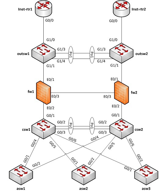
In this example, we will use a simple network. There will be Cisco switches and ITU Juniper Netscreen. We are provided with the L2 scheme, as well as the configuration files of most of the devices presented. ISP border routers configuration files are not provided, because ISP does not transmit such information in real life. Below is the L2 network topology:
And here are the device configuration files. Only the necessary information was left:
Good. Now that we have all the necessary information, we can proceed to visualization.
At this stage, we get a scheme like this:

Repeat this process step by step for each network device . Collect all the information related to IP, and display on the same scheme: every ip-address, every interface and every static route. In the process, your circuit will become very accurate. Make sure that devices that are mentioned but not yet known are displayed in the diagram. Just as we did earlier with the address 192.168.10.1 . Once you have completed all of the above for all known network devices, you can begin to ascertain unknown information. You can use MAC and ARP tables for this (I wonder if you should write the next post telling in detail about this stage?).
Ultimately, we will have a scheme like this:

It is very easy to draw a logical network diagram if you have the relevant knowledge. This is a long manual process, but it’s not magic. Once you have an L3 network diagram, it is easy enough to keep it up to date. The benefits are worth the effort:
What information should be presented on L3-schemes?
In order to create a network diagram, you need to have an accurate idea of what information should be present and on which particular schemes. Otherwise, you will mix the information and as a result you will get another useless “hybrid” scheme. Good L3 schemes contain the following information:
- subnet
- VLAN ID (all)
- VLAN names
- network addresses and masks (prefixes)
- L3 devices
- routers, firewalls (ITU) and VPN gateways (at a minimum)
- the most significant servers (for example, DNS, etc.)
- ip-addresses of these servers
- logical interfaces
- routing protocol information
What information should NOT be on L3-schemes?
The information listed below should not be on network circuits, since it refers to other levels [ OSI models, approx. per. ] and, accordingly, should be reflected in other schemes :
- all information L2 and L1 (in general)
- L2 switches (only management interface can be presented)
- physical connections between devices
Used notation
As a rule, logical symbols are used on logic circuits. Most of them require no explanation, but because I have already seen the errors of their application, then I will allow myself to stop and give a few examples:
')
- Subnet represented as a tube or line:

- A VRF or other not exactly known zone appears as a cloud:

What information is needed to create an L3 scheme?
In order to create a logical network diagram, you need the following information:
- L2 (or L1) diagram - representing the physical connections between L3 devices and switches
- L3 device configurations - text files or GUI access, etc.
- L2 device configurations - text files or GUI access, etc.
Example
In this example, we will use a simple network. There will be Cisco switches and ITU Juniper Netscreen. We are provided with the L2 scheme, as well as the configuration files of most of the devices presented. ISP border routers configuration files are not provided, because ISP does not transmit such information in real life. Below is the L2 network topology:
And here are the device configuration files. Only the necessary information was left:
asw1
!vlan 210name Servers1!vlan 220name Servers2!vlan 230name Servers3!vlan 240name Servers4!vlan 250name In-mgmt!interface GigabitEthernet0/1switchport mode trunkswitchport trunk encapsulation dot1q!interface GigabitEthernet0/2switchport mode trunkswitchport trunk encapsulation dot1q!interface vlan 250ip address 192.168.10.11 255.255.255.128!ip default-gateway 192.168.10.1asw2
!vlan 210name Servers1!vlan 220name Servers2!vlan 230name Servers3!vlan 240name Servers4!vlan 250name In-mgmt!interface GigabitEthernet0/1switchport mode trunkswitchport trunk encapsulation dot1q!interface GigabitEthernet0/2switchport mode trunkswitchport trunk encapsulation dot1q!interface vlan 250ip address 192.168.10.12 255.255.255.128!ip default-gateway 192.168.10.1asw3
!vlan 210name Servers1!vlan 220name Servers2!vlan 230name Servers3!vlan 240name Servers4!vlan 250name In-mgmt!interface GigabitEthernet0/1switchport mode trunkswitchport trunk encapsulation dot1q!interface GigabitEthernet0/2switchport mode trunkswitchport trunk encapsulation dot1q!interface vlan 250ip address 192.168.10.13 255.255.255.128!ip default-gateway 192.168.10.1csw1
!vlan 200name in-transit!vlan 210name Servers1!vlan 220name Servers2!vlan 230name Servers3!vlan 240name Servers4!vlan 250name In-mgmt!interface GigabitEthernet0/1switchport mode trunkswitchport trunk encapsulation dot1q!interface GigabitEthernet0/2switchport mode trunkswitchport trunk encapsulation dot1qchannel-group 1 mode active!interface GigabitEthernet0/3switchport mode trunkswitchport trunk encapsulation dot1qchannel-group 1 mode active!interface GigabitEthernet0/4switchport mode trunkswitchport trunk encapsulation dot1q!interface GigabitEthernet0/5switchport mode trunkswitchport trunk encapsulation dot1q!interface GigabitEthernet0/6switchport mode trunkswitchport trunk encapsulation dot1q!interface Port-channel 1switchport mode trunkswitchport trunk encapsulation dot1q!interface vlan 200ip address 10.0.0.29 255.255.255.240standby 1 ip 10.0.0.28!interface vlan 210ip address 192.168.0.2 255.255.255.128standby 2 ip 192.168.0.1!interface vlan 220ip address 192.168.0.130 255.255.255.128standby 3 ip 192.168.0.129!interface vlan 230ip address 192.168.1.2 255.255.255.128standby 4 ip 192.168.1.1!interface vlan 240ip address 192.168.1.130 255.255.255.128standby 5 ip 192.168.1.129!interface vlan 250ip address 192.168.10.2 255.255.255.128standby 6 ip 192.168.10.1!ip route 0.0.0.0 0.0.0.0 10.0.0.17csw2
!vlan 200name in-transit!vlan 210name Servers1!vlan 220name Servers2!vlan 230name Servers3!vlan 240name Servers4!vlan 250name In-mgmt!interface GigabitEthernet0/1switchport mode trunkswitchport trunk encapsulation dot1q!interface GigabitEthernet0/2switchport mode trunkswitchport trunk encapsulation dot1qchannel-group 1 mode active!interface GigabitEthernet0/3switchport mode trunkswitchport trunk encapsulation dot1qchannel-group 1 mode active!interface GigabitEthernet0/4switchport mode trunkswitchport trunk encapsulation dot1q!interface GigabitEthernet0/5switchport mode trunkswitchport trunk encapsulation dot1q!interface GigabitEthernet0/6switchport mode trunkswitchport trunk encapsulation dot1q!interface Port-channel 1switchport mode trunkswitchport trunk encapsulation dot1q!interface vlan 200ip address 10.0.0.30 255.255.255.240standby 1 ip 10.0.0.28!interface vlan 210ip address 192.168.0.3 255.255.255.128standby 2 ip 192.168.0.1!interface vlan 220ip address 192.168.0.131 255.255.255.128standby 3 ip 192.168.0.129!interface vlan 230ip address 192.168.1.3 255.255.255.128standby 4 ip 192.168.1.1!interface vlan 240ip address 192.168.1.131 255.255.255.128standby 5 ip 192.168.1.129!interface vlan 250ip address 192.168.10.3 255.255.255.128standby 6 ip 192.168.10.1!ip route 0.0.0.0 0.0.0.0 10.0.0.17fw1
set interface ethernet0/1 zone untrustset interface ethernet0/1.101 tag 101 zone dmzset interface ethernet0/1.102 tag 102 zone mgmtset interface ethernet0/2 zone trustset interface ethernet0/1 ip 10.0.0.1/28set interface ethernet0/1 manage-ip 10.0.0.2set interface ethernet0/1.101 ip 10.0.0.33/28set interface ethernet0/1.102 ip 10.0.0.49/28set interface ethernet0/2 ip 10.0.0.17/28set interface ethernet0/2 manage-ip 10.0.0.18set vrouter trust-vr route 0.0.0.0/0 interface ethernet0/1 gateway 10.0.0.12fw2
set interface ethernet0/1 zone untrustset interface ethernet0/1.101 tag 101 zone dmzset interface ethernet0/1.102 tag 102 zone mgmtset interface ethernet0/2 zone trustset interface ethernet0/1 ip 10.0.0.1/28set interface ethernet0/1 manage-ip 10.0.0.3set interface ethernet0/1.101 ip 10.0.0.33/28set interface ethernet0/1.102 ip 10.0.0.49/28set interface ethernet0/2 ip 10.0.0.17/28set interface ethernet0/2 manage-ip 10.0.0.19set vrouter trust-vr route 0.0.0.0/0 interface ethernet0/1 gateway 10.0.0.12outsw1
!vlan 100name Outside!vlan 101name DMZ!vlan 102name Mgmt!interface GigabitEthernet1/0description To-Inet-rtr1switchport mode accessswitchport access vlan 100!interface GigabitEthernet1/1switchport mode trunkswitchport trunk encapsulation dot1q!interface GigabitEthernet1/3switchport mode trunkswitchport trunk encapsulation dot1qchannel-group 1 mode active!interface GigabitEthernet1/4switchport mode trunkswitchport trunk encapsulation dot1qchannel-group 1 mode active!interface Port-channel 1switchport mode trunkswitchport trunk encapsulation dot1q!interface vlan 102ip address 10.0.0.50 255.255.255.240!ip default-gateway 10.0.0.49outsw2
!vlan 100name Outside!vlan 101name DMZ!vlan 102name Mgmt!interface GigabitEthernet1/0description To-Inet-rtr2switchport mode accessswitchport access vlan 100!interface GigabitEthernet1/1switchport mode trunkswitchport trunk encapsulation dot1q!interface GigabitEthernet1/3switchport mode trunkswitchport trunk encapsulation dot1qchannel-group 1 mode active!interface GigabitEthernet1/4switchport mode trunkswitchport trunk encapsulation dot1qchannel-group 1 mode active!interface Port-channel 1switchport mode trunkswitchport trunk encapsulation dot1q!interface vlan 102ip address 10.0.0.51 255.255.255.240!ip default-gateway 10.0.0.49Collection of information and its visualization
Good. Now that we have all the necessary information, we can proceed to visualization.
Process mapping step by step
- Collection of information:
- First, open the configuration file (in this case, ASW1).
- Take from there each ip-address from the interface sections. In this case, there is only one address ( 192.168.10.11 ) with a mask of 255.255.255.128 . The interface name is vlan250 , and the name vlan 250 is In-mgmt .
- Take all static routes from configuration. In this case, there is only one (ip default-gateway), and it points to 192.168.10.1 .
- Display:
- Now let's display the information we collected. First, draw an ASW1 device. ASW1 is a switch, so we use the switch symbol.
- Draw a subnet (tube). Assign the name In-mgmt , VLAN-ID 250 and address 192.168.10.0/25 .
- Connect ASW1 and subnet.
- Insert the text box between the ASW1 and subnet symbols. Let's display in it the name of the logical interface and the ip-address. In this case, the interface name will be vlan250 , and the last octet of the ip-address is .11 (this is common practice — display only the last octet of the ip-address, since the ip-address of the network is already on the diagram).
- There is also another device on the In-mgmt network. Or, at least, should be. We still do not know the name of this device, but its IP address is 192.168.10.1 . We learned this because ASW1 points to this address as the default gateway. So let's display this device in the diagram and give it a temporary name "??". We also add its address to the scheme - .1 (by the way, I always highlight inaccurate / unknown information in red so that looking at the scheme you can immediately understand what needs clarification on it).
At this stage, we get a scheme like this:
Repeat this process step by step for each network device . Collect all the information related to IP, and display on the same scheme: every ip-address, every interface and every static route. In the process, your circuit will become very accurate. Make sure that devices that are mentioned but not yet known are displayed in the diagram. Just as we did earlier with the address 192.168.10.1 . Once you have completed all of the above for all known network devices, you can begin to ascertain unknown information. You can use MAC and ARP tables for this (I wonder if you should write the next post telling in detail about this stage?).
Ultimately, we will have a scheme like this:
Conclusion
It is very easy to draw a logical network diagram if you have the relevant knowledge. This is a long manual process, but it’s not magic. Once you have an L3 network diagram, it is easy enough to keep it up to date. The benefits are worth the effort:
- you can plan changes quickly and accurately;
- problem solving takes much less time than before. Imagine that someone needs to solve the problem of unavailability of service for 192.168.0.200 to 192.168.1.200. After reviewing the L3 scheme, it is safe to say that ITU is not the cause of this problem.
- You can easily follow the correctness of the rules of the ITU. I have seen situations where ITU contained rules for traffic that would never pass through this ITU. This example perfectly shows that the logical network topology is unknown.
- Usually, as soon as the L3 network diagram is created, you will immediately notice which parts of the network do not have redundancy, etc. In other words, the L3 topology (as well as redundancy) is just as important as redundancy at the physical layer.
Source: https://habr.com/ru/post/230439/
All Articles