How PolyITAN-1 was born in KPI laboratories
Design and manufacture
The satellite was conceived for a long time, although there was no well thought-out development plan as such, one could say there was a desire to start developing a satellite without official support from the Ukrainian Space Agency and the presence of a satellite at an early stage of development in the plans of our National Technical University of Ukraine "KPI" . The desire arose not out of the blue, at the Department of Nuclear Power Plants and Engineering Thermophysics at the Thermal Power Engineering Faculty of the KPI behind a long history of close cooperation with the space industry. So, for cooling and thermal stabilization of electronics on artificial satellites Sich and Okean, space probes Vega and Phobos, several German satellites and one Czech satellites used our heat pipes. But even with the help of the faculty, it was impossible to draw the whole range of work, because specialists from other departments were looking for - employees from the FEA, FEL, RTF were invited to work, information was collected, and various consultations were held at conferences, as this is the first satellite. Part of the work that could be done under the pretext of the relevant research studies of the faculty was done in advance. Naturally, most of them later had to be redone, but experience in this matter is not superfluous.
For example, the first version of the satellite hull, sheathed by centimeter cell panels, looked like this:
')
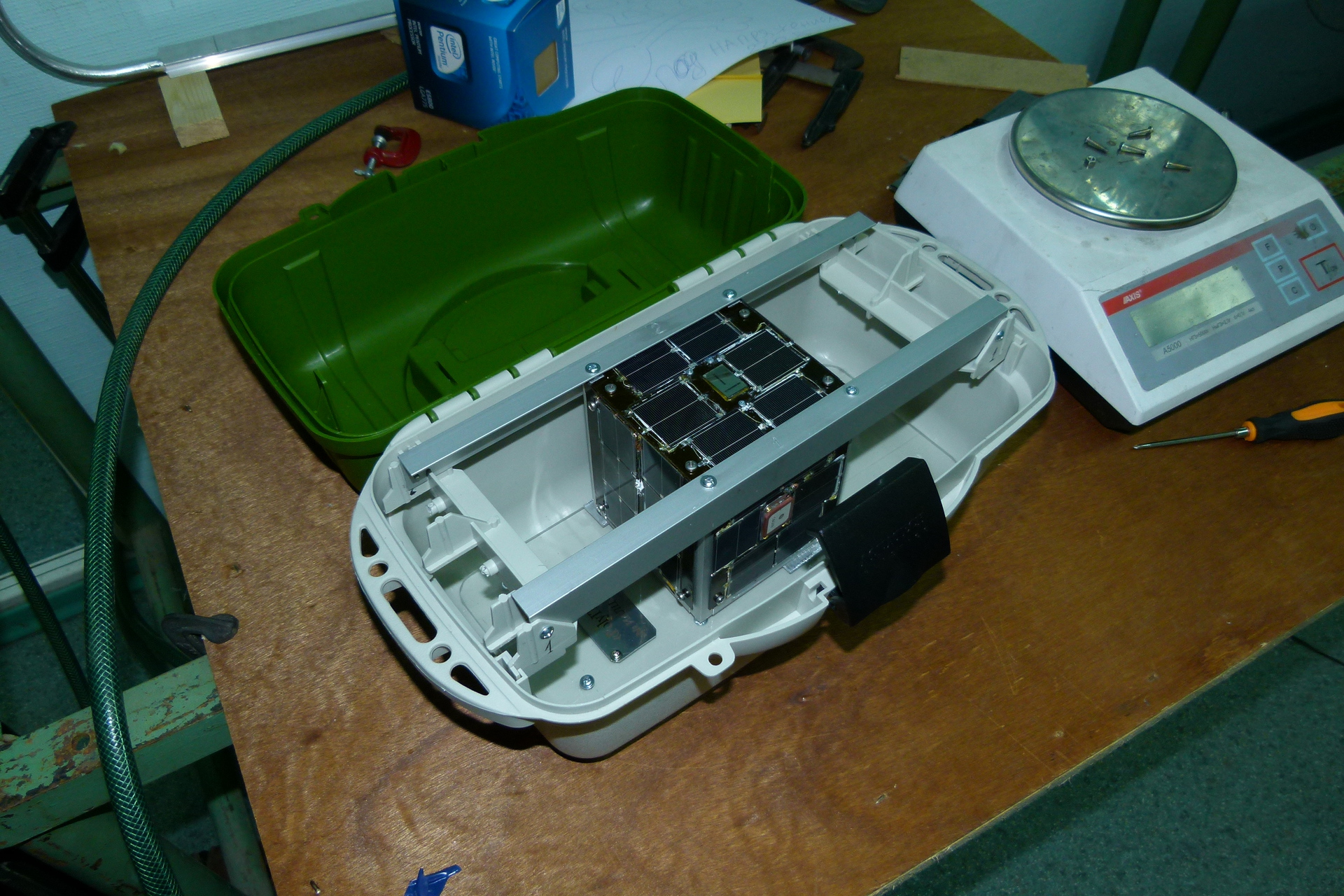
As information was gathered, it turned out that many problems could be avoided by bringing the satellite to the CubeSat format and paying for a place in a group launch with other satellites. The thickness of the cell panels decreased almost three times, the undocking mechanism was not needed, and the satellite itself should fit inside the test structure, which is called a canister, and was kindly offered to us at ISIS , Delft (Holland).
Test canister (we prefer to call it a platform) QuadPack to check the dimensions, the satellite inside should slide freely.
Work on a three-dimensional satellite model is not a problem; only cosmic specificity is added to the drawings with the obligatory indication of the design coordinate system, the associated coordinate system and the orbital coordinate system, and the orientation of the sensors in these coordinate systems is also indicated. Orientation algorithms need to correctly convert measurement results using transition matrices from one coordinate system to another. In addition, the three-dimensional model is the easiest way to calculate the center of mass and the moments of inertia of a satellite with open antennas.
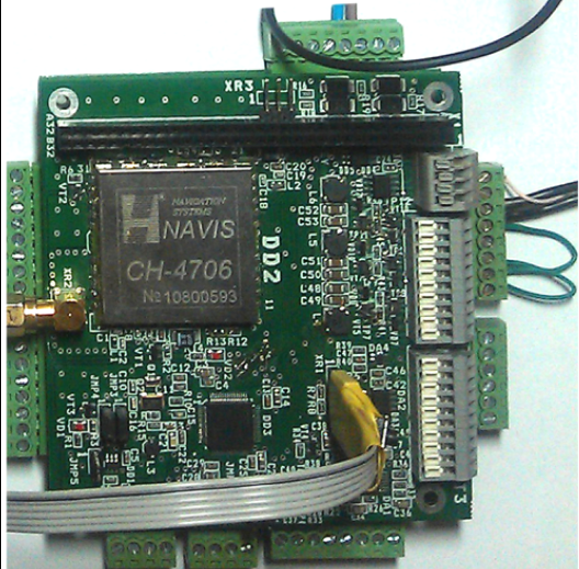
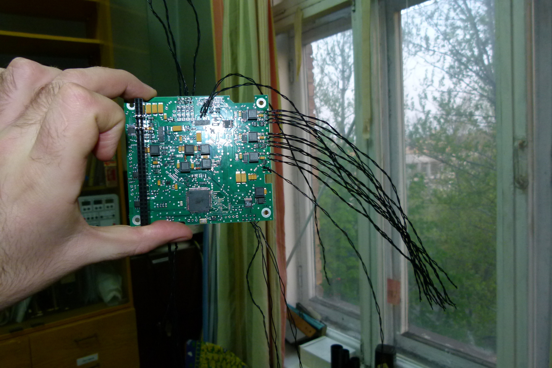
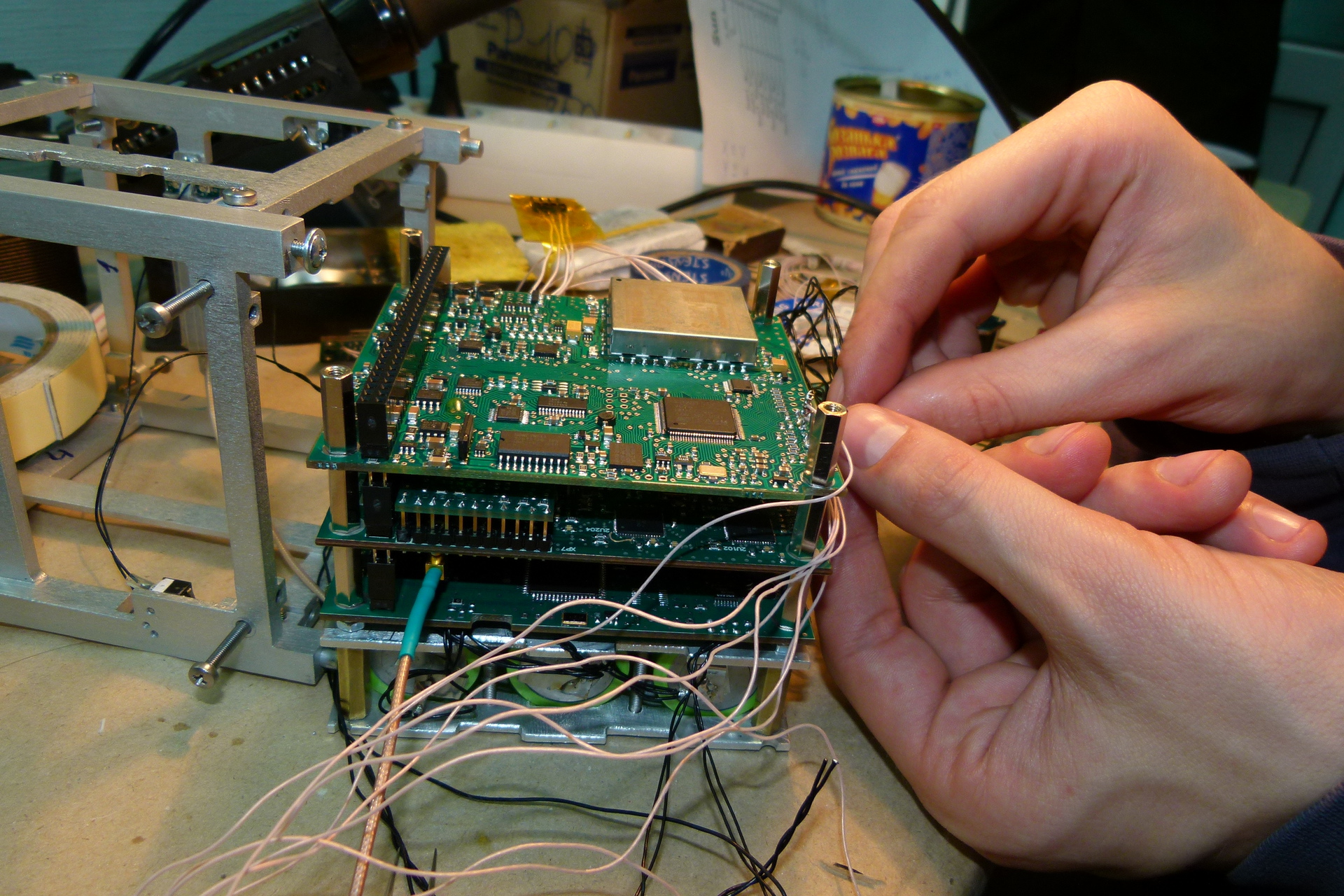
The board of the on-board computing complex (the BVK board in the photo with the installed GPS receiver from Navis-Ukraine ) was developed on our TEF by a specialist in embedded systems hired specifically for working with a satellite. In the process of testing, we managed to burn the COM port on the GPS receiver several times.
The first version of the board BVK:
The radio link was developed at the KPI Radiotechnical Faculty, two radio channels were laid: one works in the amateur radio VHF band at a frequency of 437.675 MHz (wavelength ~ 70 cm) and serves to transmit the beacon signal in the telegraph (CW) and telemetry at a speed of 9600 bps and the other for data transmission in the amateur radio range of 145 MHz.
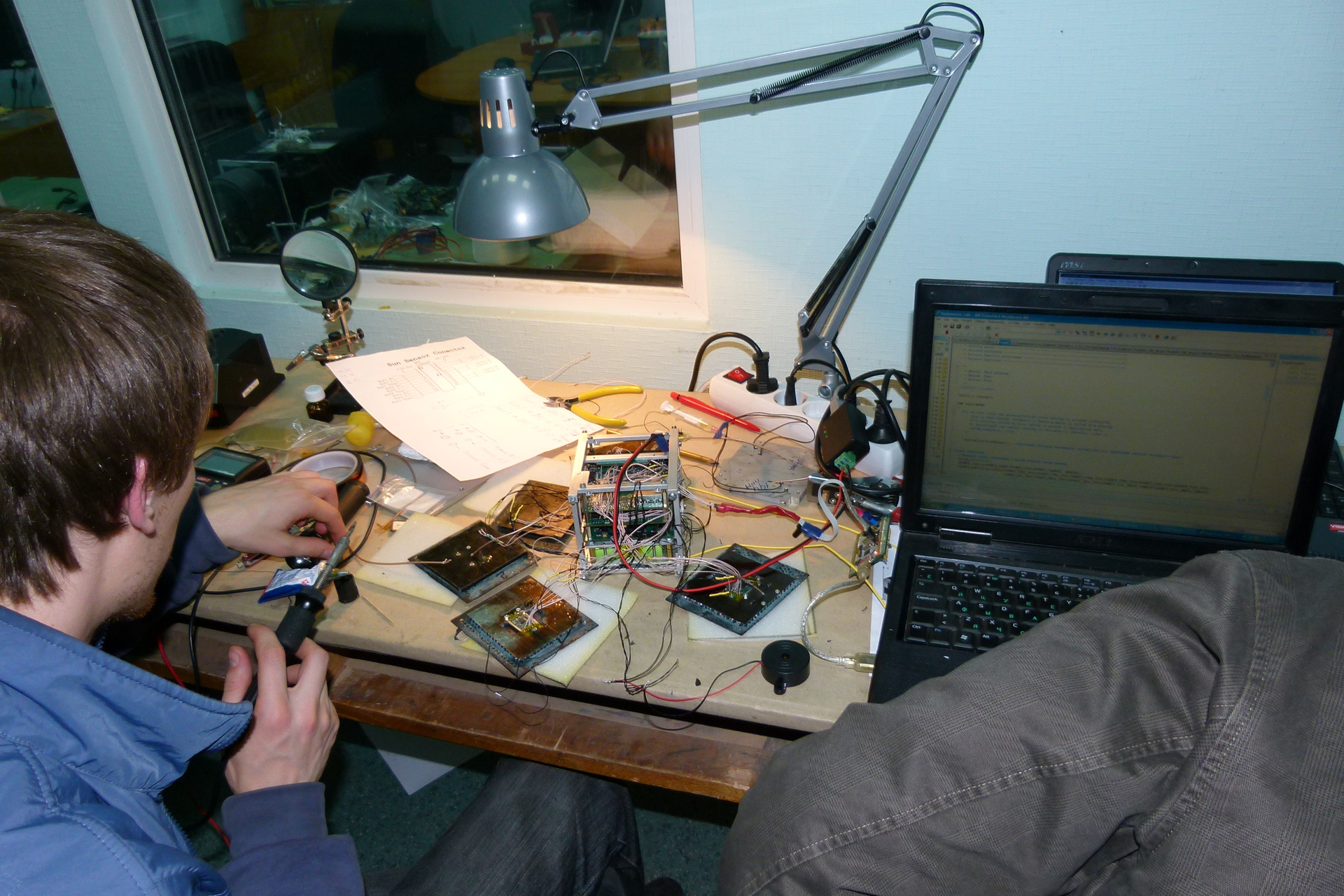
Photo during software development fee:
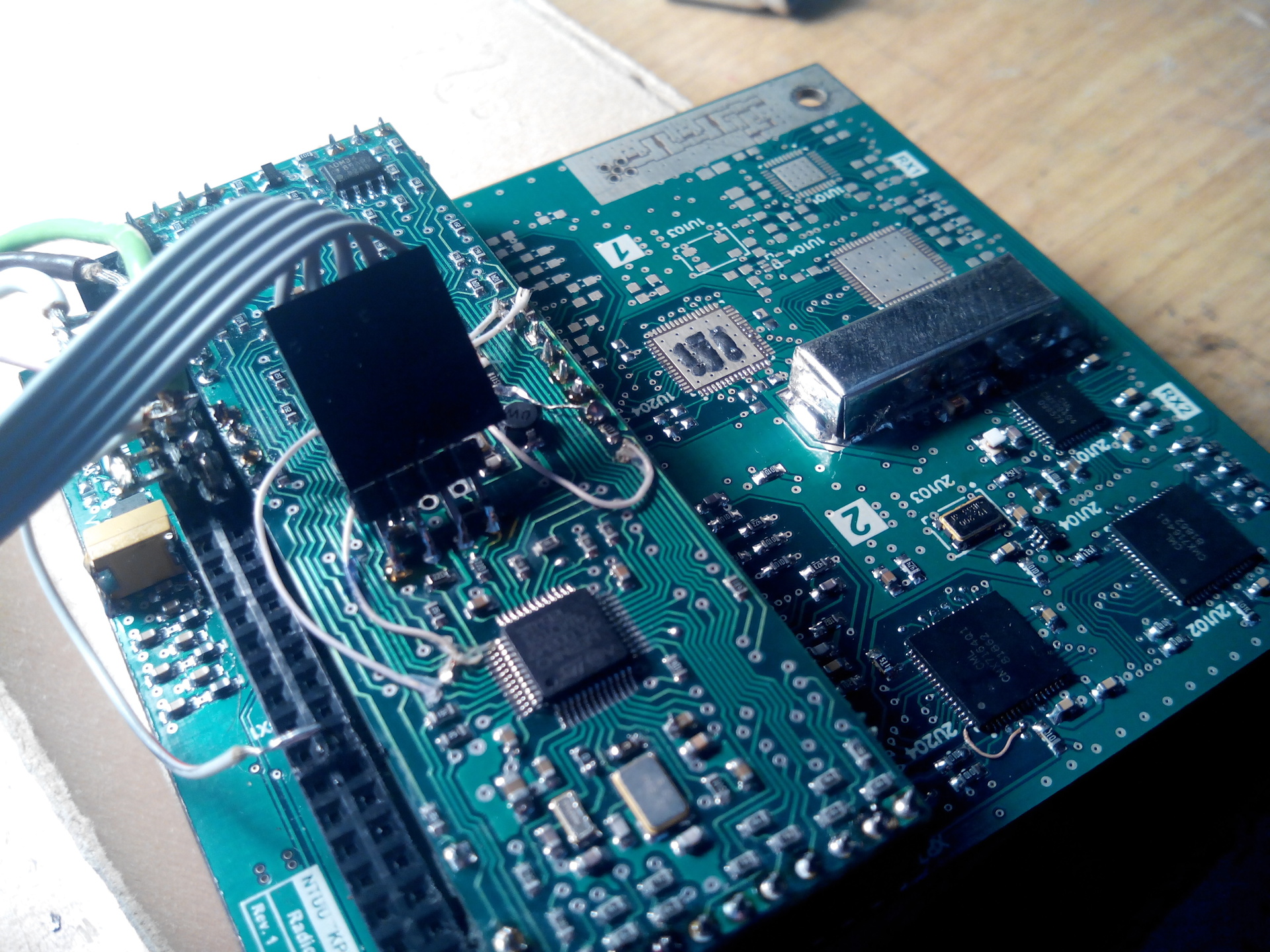
When she was already working, she was particularly pleased with the work of receiving / transmitting data together with the IOO board. For two months in the laboratory there was a “squeak” from the ground receiver. You can listen to the "melody" on the site of the radio amateur UY2RA .
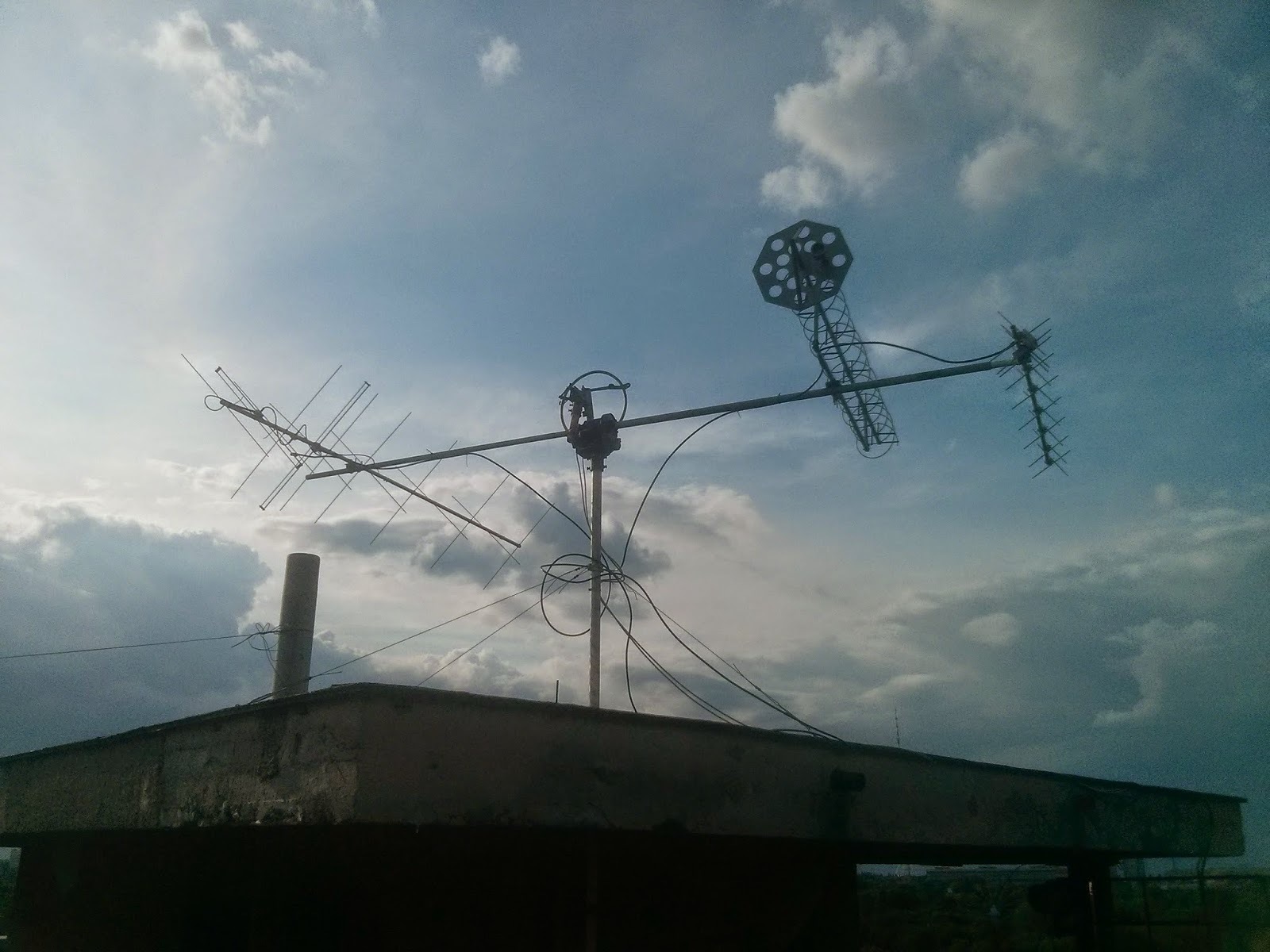
Students with RTF and TEF were engaged in installation of the KPI antenna equipment on the roof of the fifth building and cable laying from the roof to the seventh floor, where we have the control center.
Our antenna industry:
Fee subsystem power with notches for wires. It was developed by a postgraduate student at the KPI electronics department, he also chose LiFePO3 batteries and wrote software for his board:
All boards were manufactured at the “Kiev Radar Plant” .
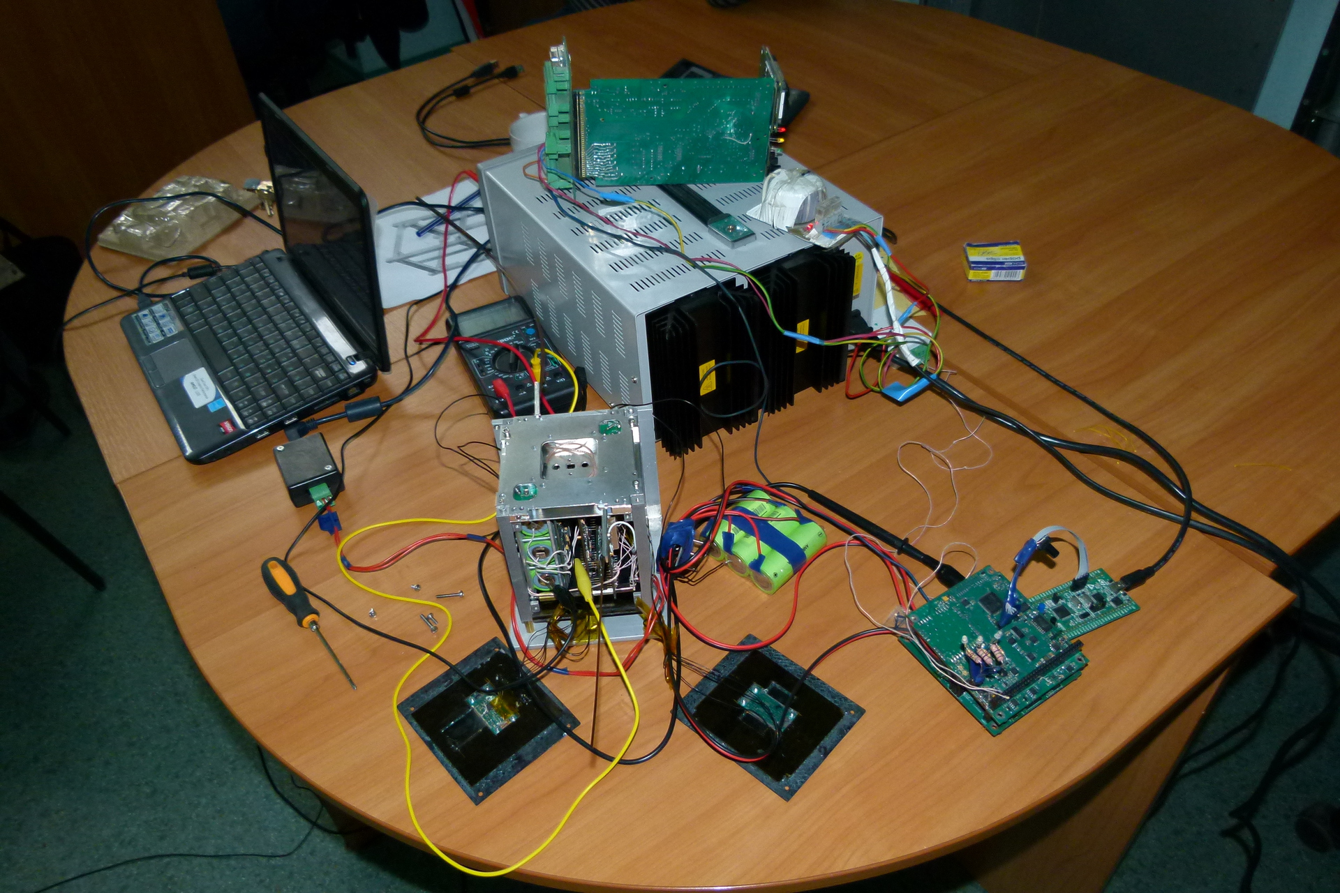
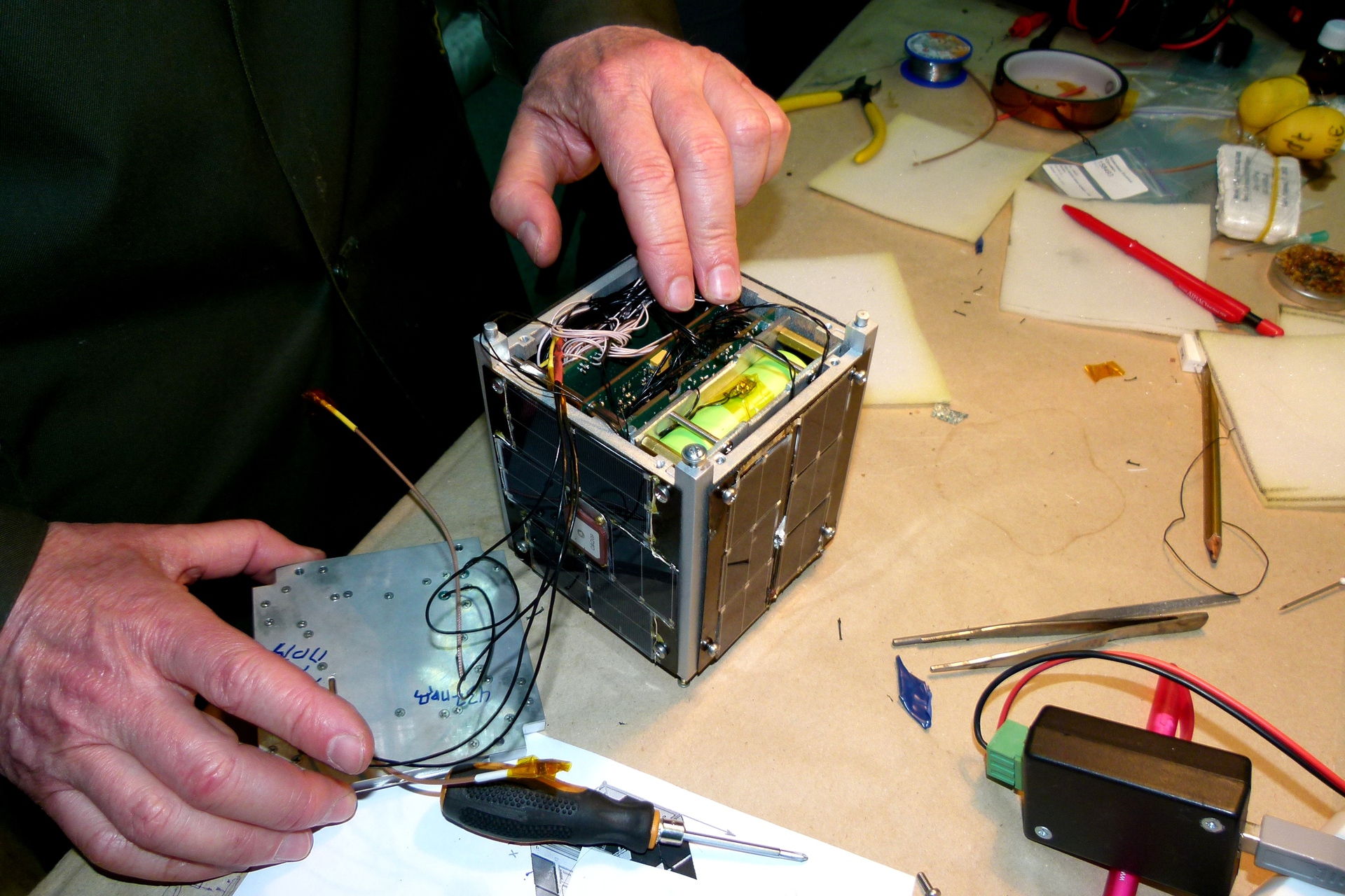
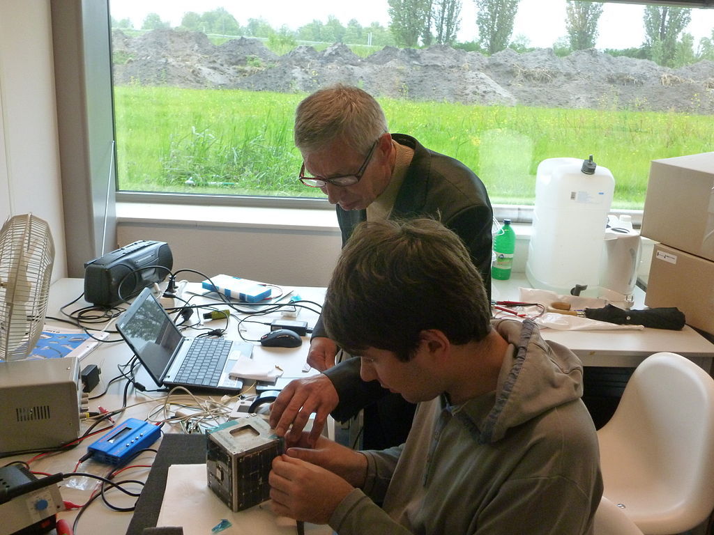
By bringing the boards together, they worked out various algorithms and modes of the satellite for quite a long time. The usual state of the workplace: the power supply using a semi-disassembled device that simulates solar panels with falling into the shadow of the Earth, feeds the satellite with batteries. They checked in which modes the batteries have time to charge, and in which not.
The photo immediately two satellites, in different versions of composure:
To control the orientation in such small satellites, magnetic coils are usually used that interact with the Earth’s magnetic field and rotate the satellite. Interestingly, an old book of more than 35 years old by Kovalenko AP was used to calculate them. Magnetic Spacecraft Control Systems 1975 At the debugging stage, resistors with two-color diodes, which can be found in the photo above, were soldered instead of coils.
If we talk about the complexity of software BVK, then it is easier to list the implemented tasks:
- onboard real time clock with GPS update;
- satellite modes and their switching on the basis of various data;
- module of work with cyclograms;
- work with GPS / GLONASS receiver using BINR protocol;
- MODBUS protocol;
- work with non-volatile flash memory for storing telemetry;
- the module for collecting and storing telemetry in the archive;
- navigation algorithms (calculation and refinement of the orbit using GPS data);
- orientation and stabilization algorithm;
- coil control module;
- work with sensors of magnetic field, angular velocity, direction to the Sun;
- interaction with power supply and radio links;
- a mechanism for putting the kernel into sleep mode to reduce power consumption when there are no executable tasks;
The necessary amount of software code for the needs of the satellite to program its three boards does not end. For practicing navigation, orientation and stabilization in the material lab, a satellite flight simulator in orbit was written with simulations of measurements of angular velocity sensors, magnetometers and sensors pointing to the Sun. The ground control center also requires software for parsing and storing the archives of the full satellite telemetry, for creating cyclograms and sending them to the satellite, for managing reconfigurable satellite parameters, and all this via the MODBUS protocol. It was not the best decision to charge the programming of the ground station to students 3-4 years before launch. The code subsequently once completely corresponded from scratch, and the graduating students, due to employment in their main job, could not find time to support the software they had created. In addition, for radio amateurs, a small telemetry parsing program from the beacon packets is required.
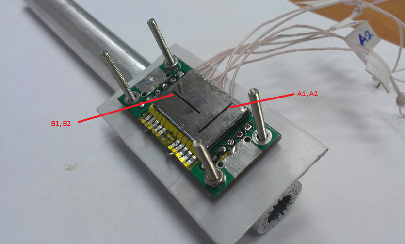
Sensor direction to the sun. We have been developing and manufacturing at KPI. If you briefly describe the device of the sensor, then this is a small solar battery with four sections of current pickup, covered with an opaque panel with two mutually perpendicular slots. The outputs from the photocell go to the microcircuit to amplify the signal, which can then be measured by the ADC on the BVK board. After processing the captured data, you can get a vector pointing to the sun.
Photocell of our sensor.

The sensor itself with the panel closed, on the reverse side is the signal amplifier chip:
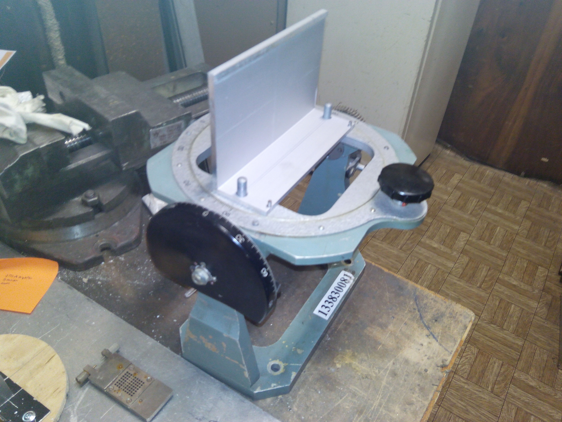
Oddly enough, the biggest problem in working out the sensor was to find for him a two-axis rotary stand with markings of the corners. The quality of lighting was answered by our simulator for the atmospheric solar radiation, the same as for the thermal vacuum tests of our satellite. What will be a little lower in the text.
Wanted stand:
During the calibration process, you should not forget that the planet Earth also successfully reflects the light and should be taken into account in the errors:
Sensors for continuous tracking of the vector of the direction to the Sun should be on each face of the satellite, but in our case they are smaller.
Tests
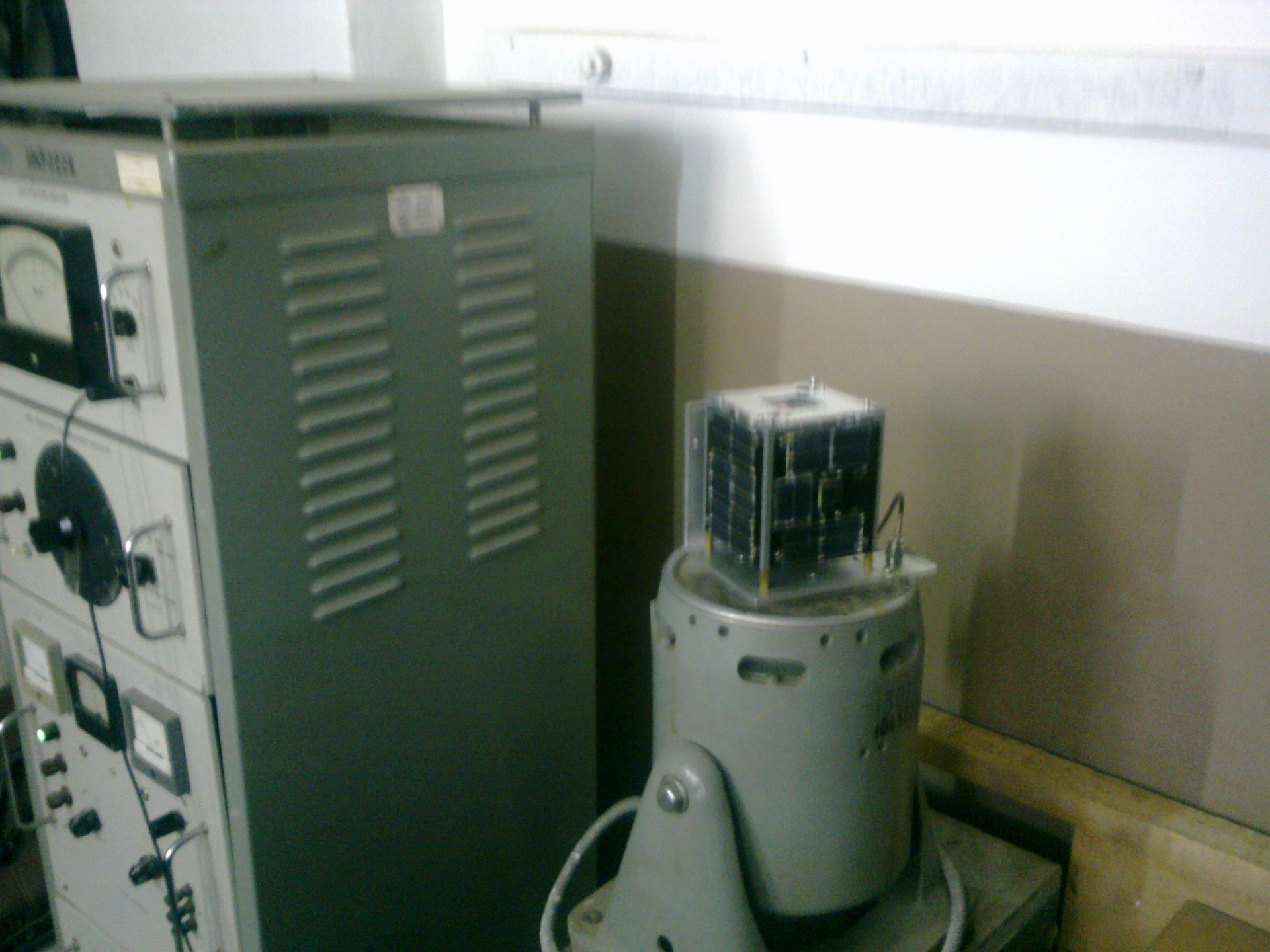
Vibration tests. Testing equipment still Soviet production. The satellite must withstand vibrations and not fall apart. Information on overloads depends on the launch vehicle and in our case had the following values: axial longitudinal overload - 7.5 g, transverse overload - 0.8 g, integrated acoustic load - 140 dB.
Photo of the shaker unfortunately only from mobile:
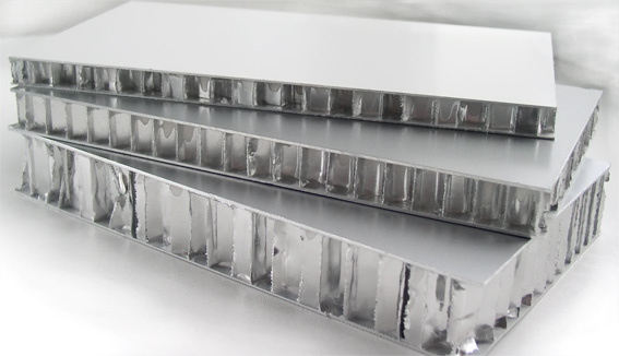
Thermo-vacuum tests. Conducted entirely with our own department in one of the divisions www.lab-hp.kiev.ua . During the tests, the conditions and the influence of space factors were simulated: low temperature, vacuum, solar and terrestrial radiation, blackness of space, which affect the temperature regime of electronic equipment and its reliability. Thermal Power Department just specializes in such, because the tests were carried out on their own with a detailed description of the programs, techniques and release of scientific articles. PolyITAN-1 is protected from the cold of outer space by our mobile panels, which are lightweight aluminum honeycomb cores (honeycombs 5 mm high made of foil 0.023 mm thick) pasted over from both sides with carbon-fiber cladding with a dielectric polyimide film.
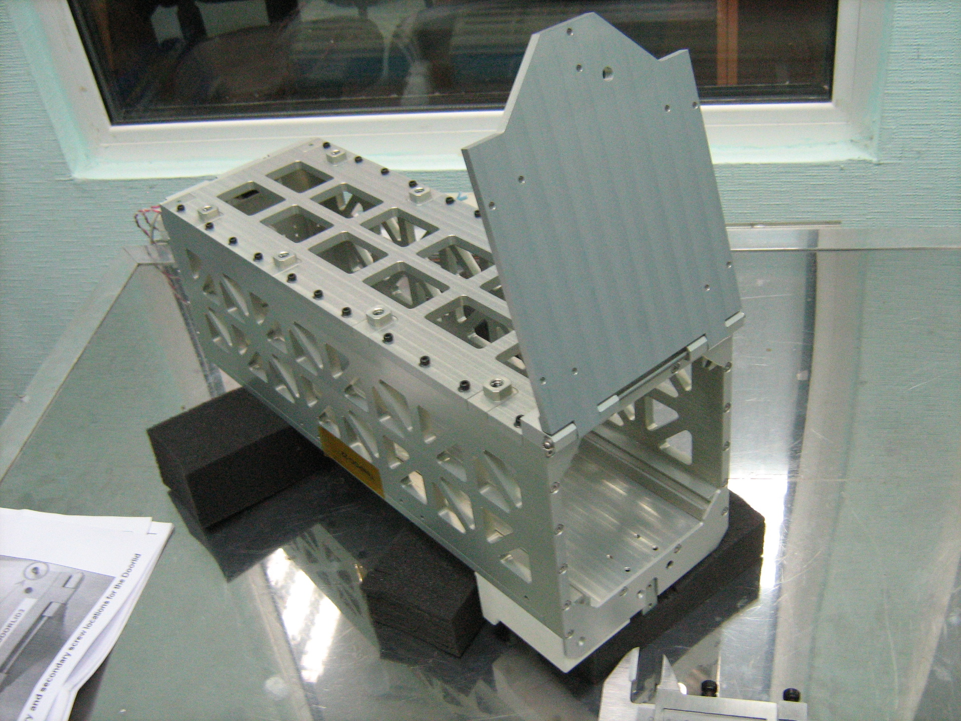
Aluminum panels with aluminum covers:
The solar simulator should provide 1400 W per square meter, for large objects it can sometimes look like a solarium panel and be placed in a vacuum chamber with the test object. In our case, the simulator is external. The light source penetrates the vacuum chamber through a small window and a window in a cryopanel, a nitrogen screen with a temperature of -193 ° C and a degree of blackness greater than 0.93.
White stickers are just thermocouples for temperature control:
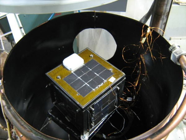
An open thermal vacuum chamber, an internal nitrogen screen with thermocouples is visible, an old satellite version looks out of the slot in the porthole.
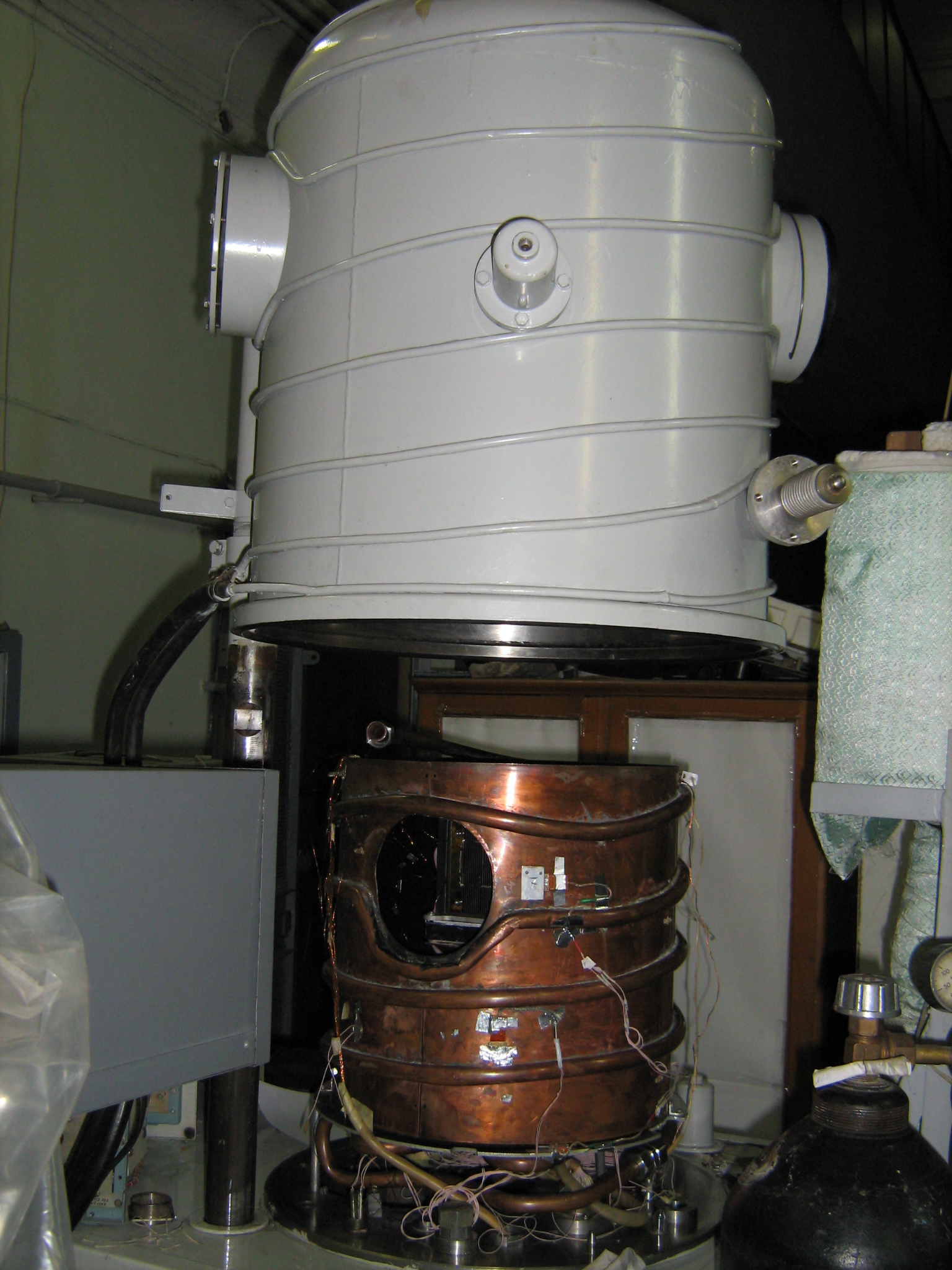
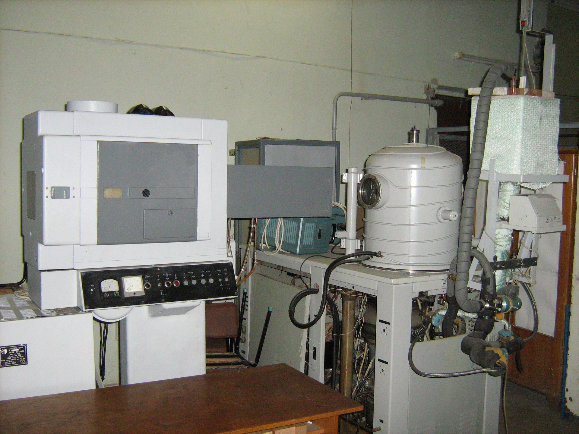
In the photo there is a general view of the equipment, on the left there is a solar radiation simulator gun, and it is difficult not to recognize the vacuum chamber with a porthole.
The test results showed temperature fluctuations on the faces of the nanosatellite solar cells from -32 ° C in the shade and up to 65 ° C under the Sun. The temperature inside the satellite was within the tolerance for the equipment. The batteries kept within the limits of +5 ... +9 ° , the microcontroller warmed up from +5 to +23 ° .
Radiation exposure. The tests were carried out on the M-30 microtron of the Institute of Electronic Physics of the National Academy of Sciences of Ukraine, Uzhgorod. The degree of degradation of electronic components and solar batteries of the nanosatellite was tested. From what they told me, the situation is as follows: electrons with an energy of 7 MeV eject from the microtron and knock out from the screen gamma radiation, which already falls on working boards and solar batteries. Irradiation with a duration of about three hours (two approaches 5578 s + 5578 s) simulates the effect of radiation for 18 months in near-Earth space. The boards began to fail by the end of the first 1.5 hours of testing. The degree of degradation of solar cells was only 3-5% and was calculated based on the current removed before and after testing with the same luminous flux.
Photo of the M-30 microtron from the IEF website:

Sensor calibration. Absolutely all sensors on the satellite must be calibrated. Some of them are most important because they are used in orientation and stabilization. These are magnetometers, angular velocity sensors (OLSs), and sun direction sensors. The rest are more related to the state of the satellite: temperature sensors, as well as conditional sensors on antennas opening, battery charge, solar current, consumed current of various subsystems. About the sensor of the direction to the Sun was described above, the calibration of the other sensors necessary for orientation was carried out outside the KPI. In our satellite, duplication is used, for a total of twelve CRS sensors and magnetometers. All of them are electronic components on the PCB. Among the shortcomings, we can mention the extreme inaccuracy of the DOS at low speeds, and the magnetometers should ideally be located outside and not inside the satellite, which adds to the error of the distortion from the satellite design.
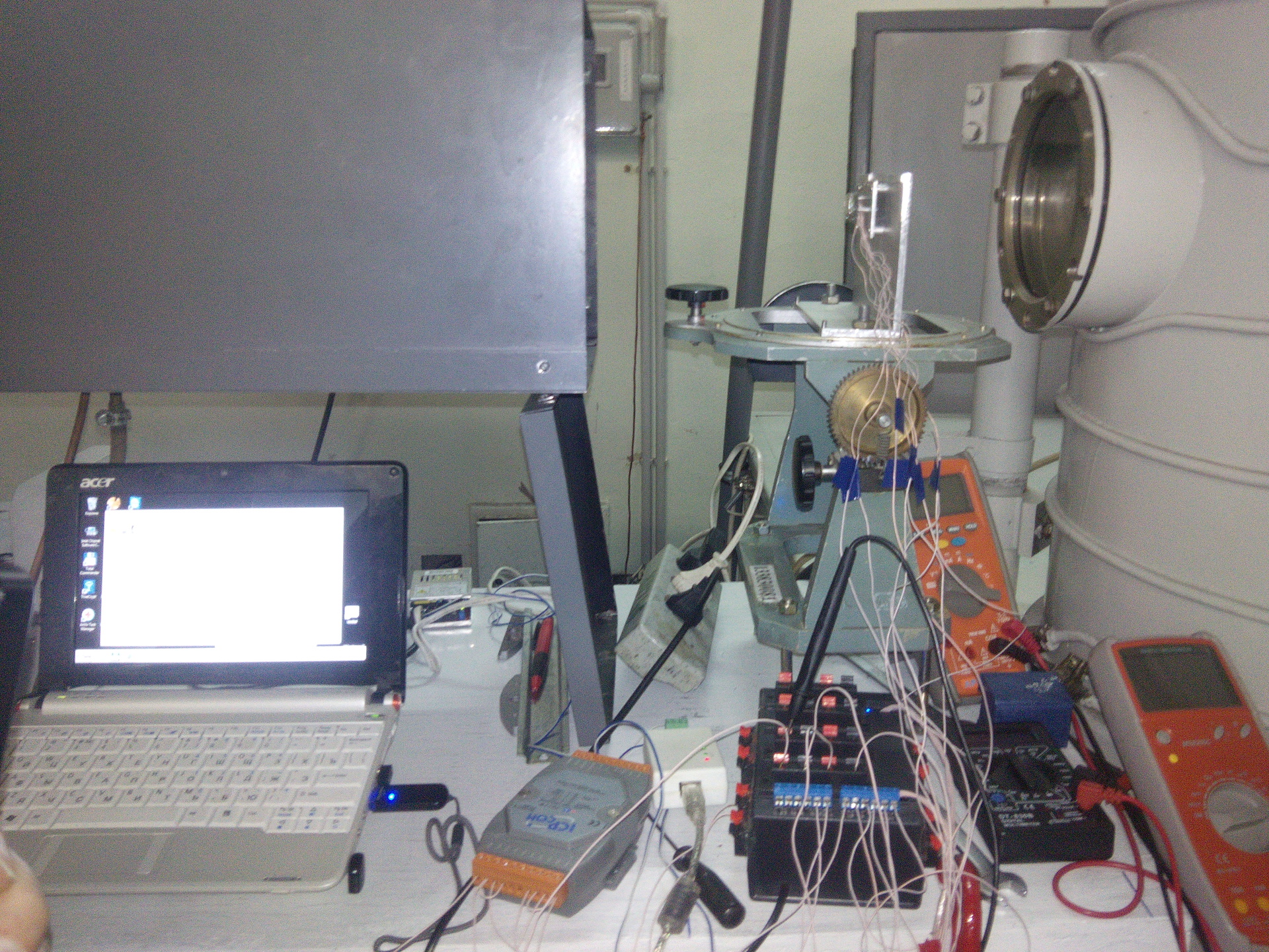
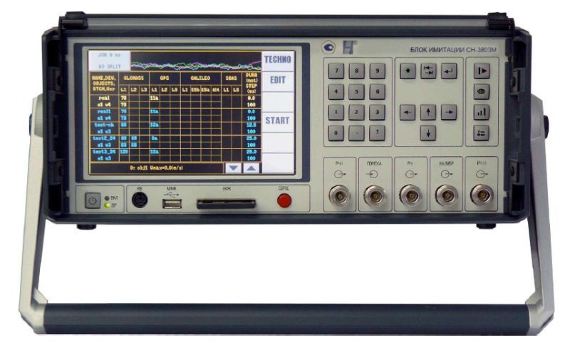
Testing the GPS / GLONASS receiver and our navigation algorithms. The Navis-Ukraine company in Smela provided us with the opportunity to test our navigation subsystem on their equipment. It was important for us to check the accuracy of the mathematical calculation and the orbit refinement on real data from the reception of the GPS / GLONASS signal at the antenna and before using the obtained calculation data for satellite orientation. The GPS / GLONASS simulator allows you to simulate a signal coming from navigation satellites, as if we were flying in a given orbit. Such a device is quite expensive and it should include software that translates the values of successive points of the orbit or points of the ground route into a data file for the simulator. For the specified time interval (orbit or route), the orbits of the selected navigation satellites are calculated, after which for each satellite the outgoing signals and the time of their arrival at the orbit points are calculated taking into account the STR. The obtained data for the simulation is recorded on a flash drive, which is already used in the GPS / GLONASS signal simulator. The simulator output is connected instead of the receiver antenna and launched for execution.
GPS / GLONASS simulator:
Check antenna combing. The only moving part in the entire structure of the satellite is the mechanism responsible for opening the antennas after launch into orbit. The satellite itself, located inside the launch canister, is in the off state. But already after being released into space, the contact of the battery supply is released, the switched on satellite with some delay should open the antennas. This is quite an important and crucial stage in the life of any spacecraft.
The antennas of our companion look like a tape of ordinary roulette, constantly striving to turn around and straighten up. In the collapsed state, the antennas are held by limiters, when current is applied, these limiters burn out and release the antennas.
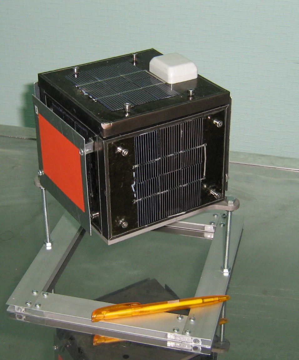
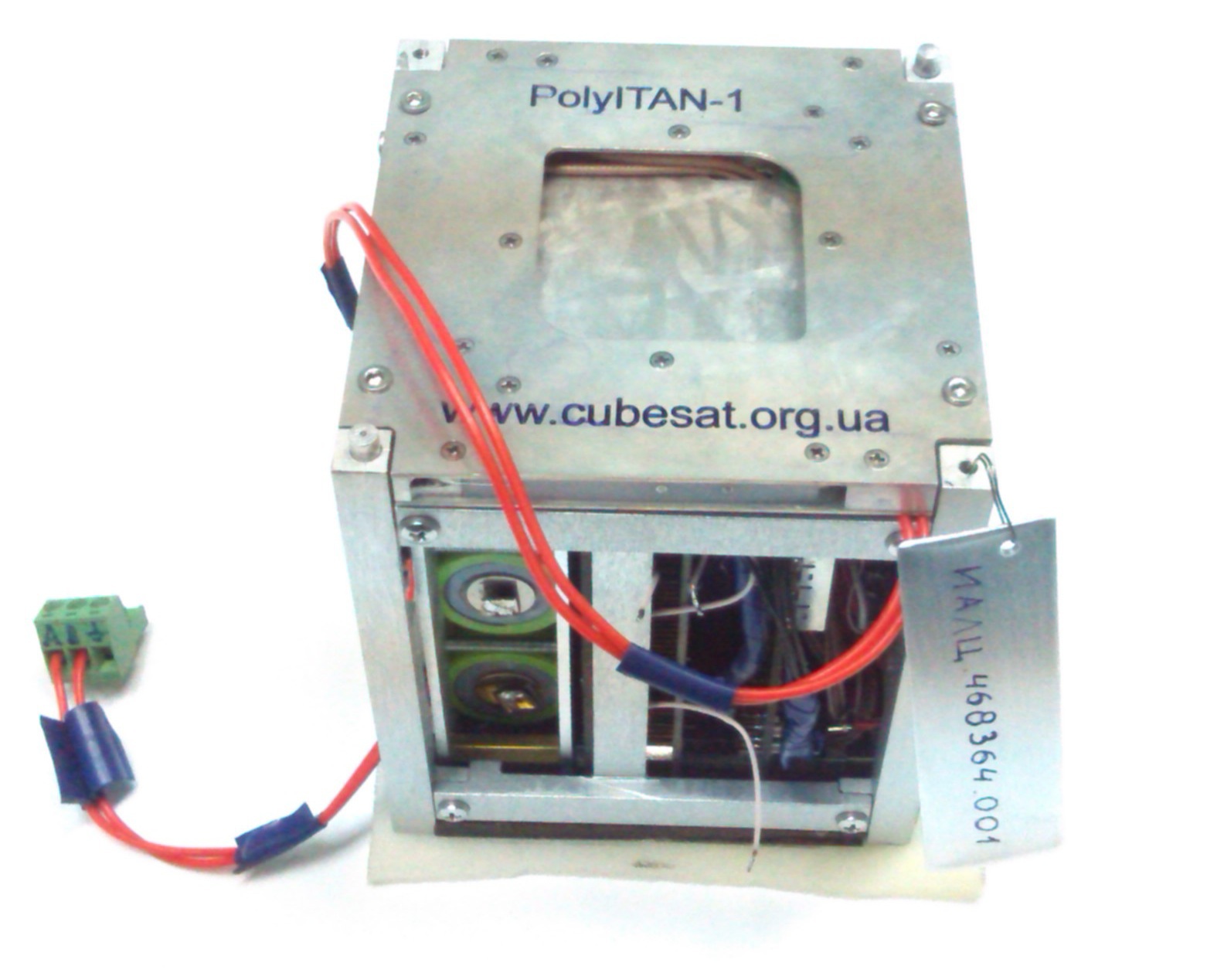
On the photo satellite with deployed antennas:
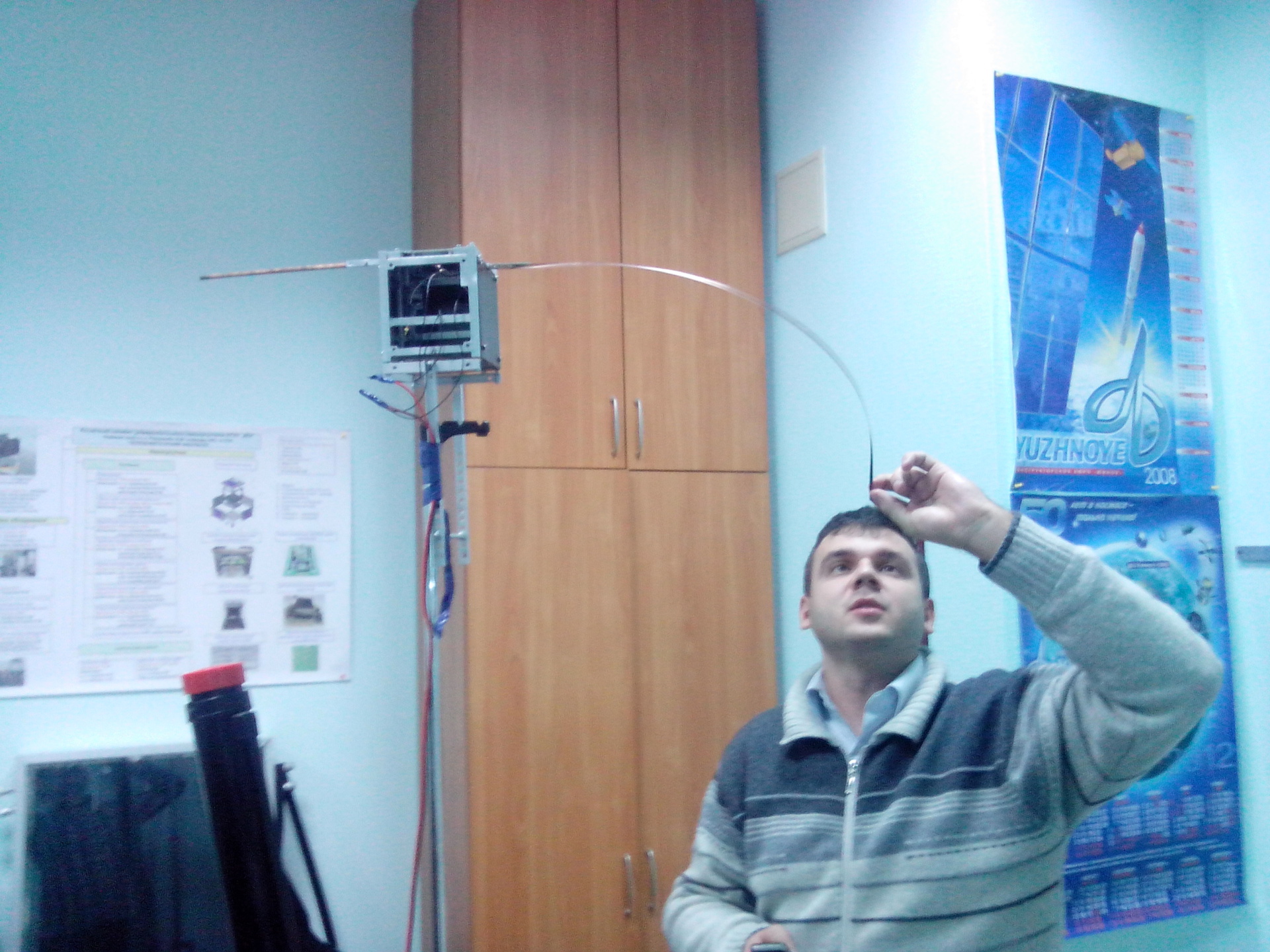
Antenna Patching Test:
Assembly and road to launch
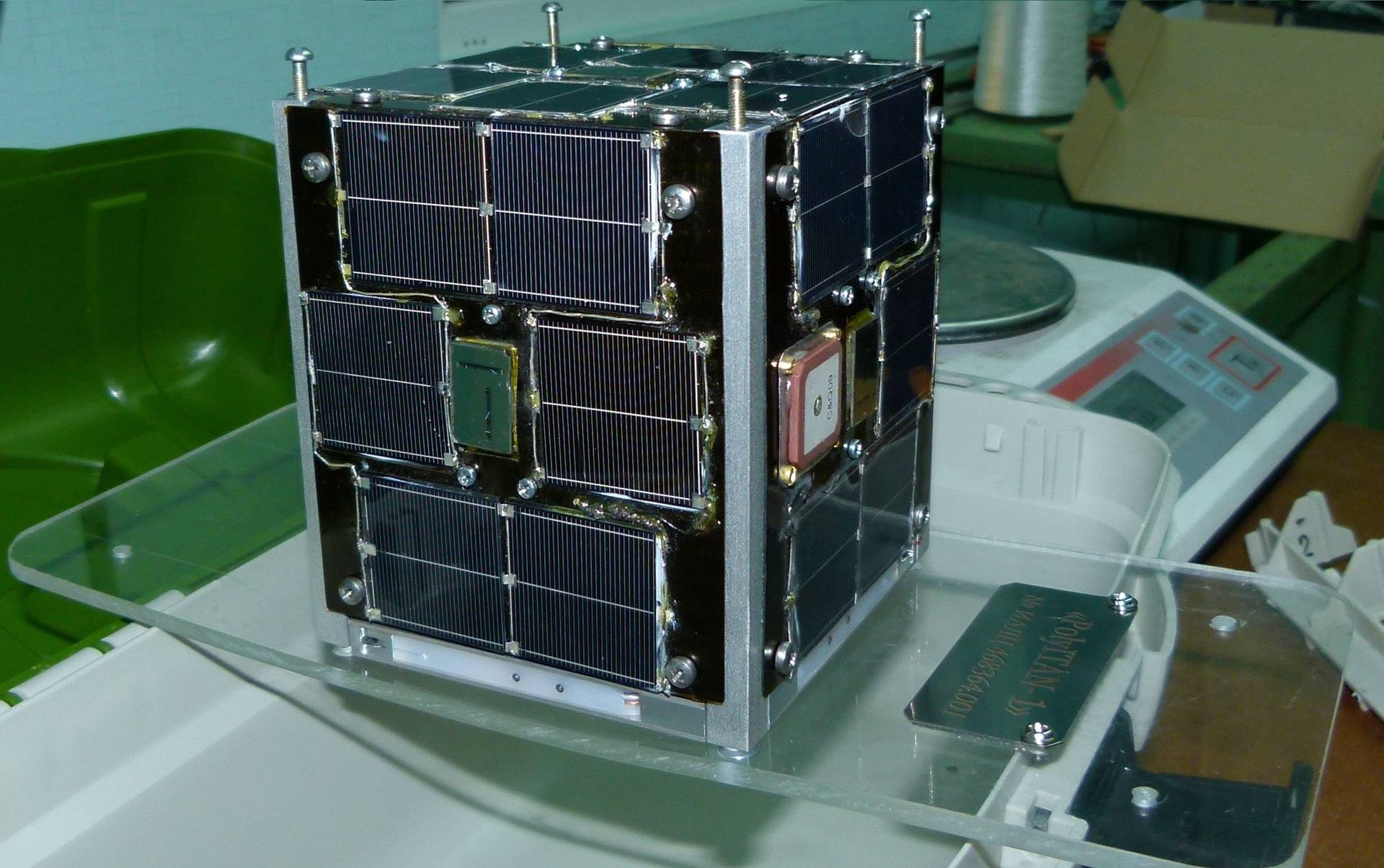
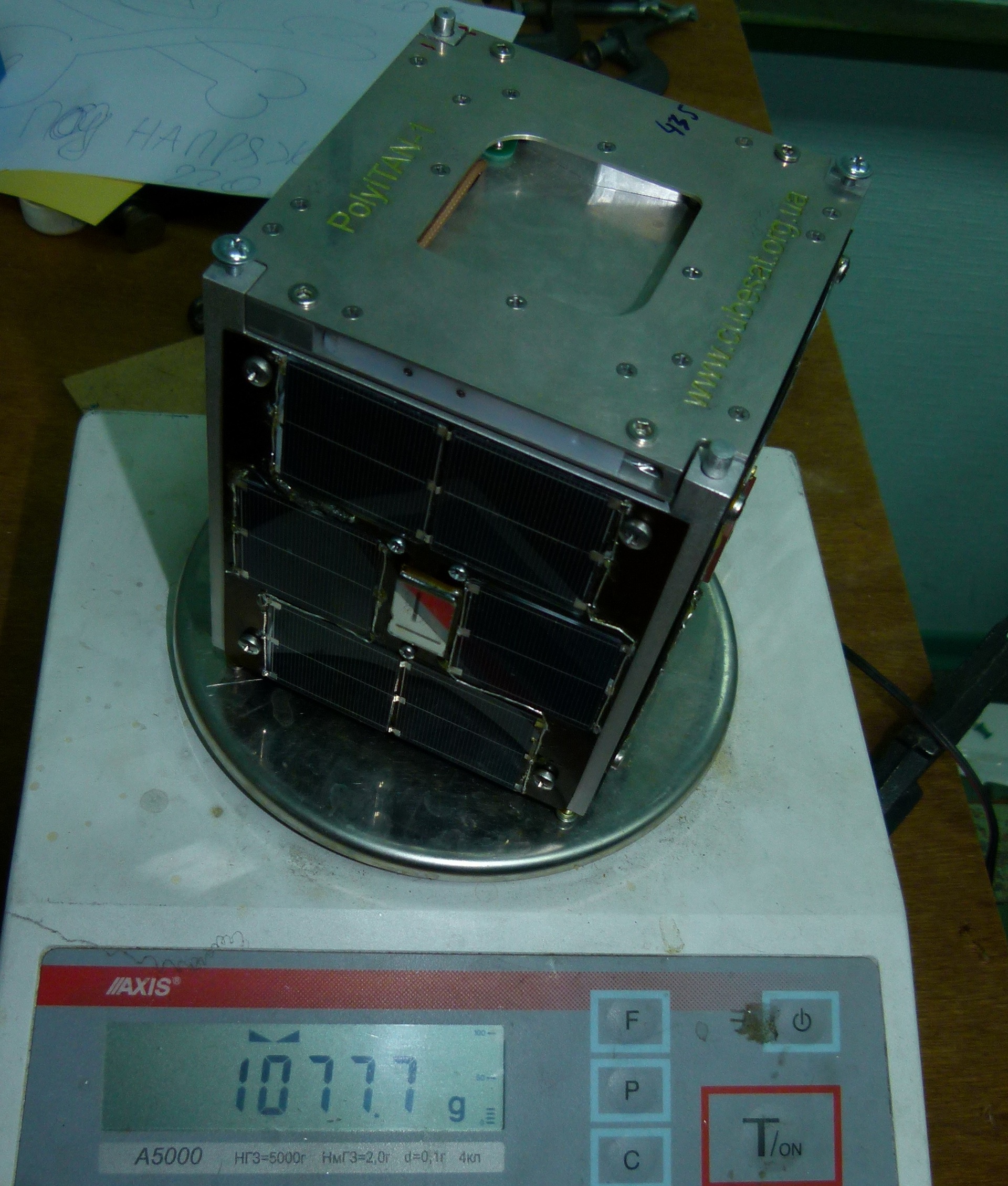
Assembly in the basement of the laboratory, together with checking all the connected elements took more than a day. A fairly demanding job, performing which you need to connect the boards according to the assembly drawings, wiring all the satellite elements into a single system (boards, external sensors, batteries, solar batteries, antenna pickup mechanism, control magnetic coils), connect the radio and GPS / GLONASS antennas, To install the direction sensors on the Sun correctly on the panels, fasten the panels themselves to the satellite. And at the end prepare the satellite for transportation:
Control weighing showed a beautiful number:
On the road:
In general, launching a satellite requires strong interaction with various government agencies and paperwork to obtain various permits. This is the most uninteresting and unpleasant part in its development, which unfortunately is impossible to get rid of. If the satellite was not created in the capital of Ukraine, then at least one employee would have lived on business trips. Receiving working frequencies at the state and international level, as well as paperwork for customs clearance can be extended for a long time. The procedure of international registration takes a lot of time, starting from “UkrDCradiofrequencies”, “UkrSpetszv'azku”, “Ukrkosmos” and up to ITU. In Ukraine, this procedure for university amateur satellites was carried out for the first time. In addition, the ITU requires starting the registration procedure two years before launch. Paperwork for customs is also a serious challenge associated with the need to prove the absence of state secrets. However, the presence of these documents does not exempt from looking at the insides of our satellite when crossing the border, one panel had to be unscrewed.
So the satellite appeared before the employees of the Border Service who were doing their duty:
A good moment can be called a repeated transfer start. From the initial planned date for December 2013 to the launch on June 19, 2014, half a year passed, which allowed us to fine-tune a couple of subsystems on the satellite, but we barely managed to do something anyway. The issue of skipping the start-up was quite acute.
The final adjustment is already in Holland before being loaded into the QuadPack platform:
Official and mandatory photo session for the satellite. Photo from blog.isilaunch.com
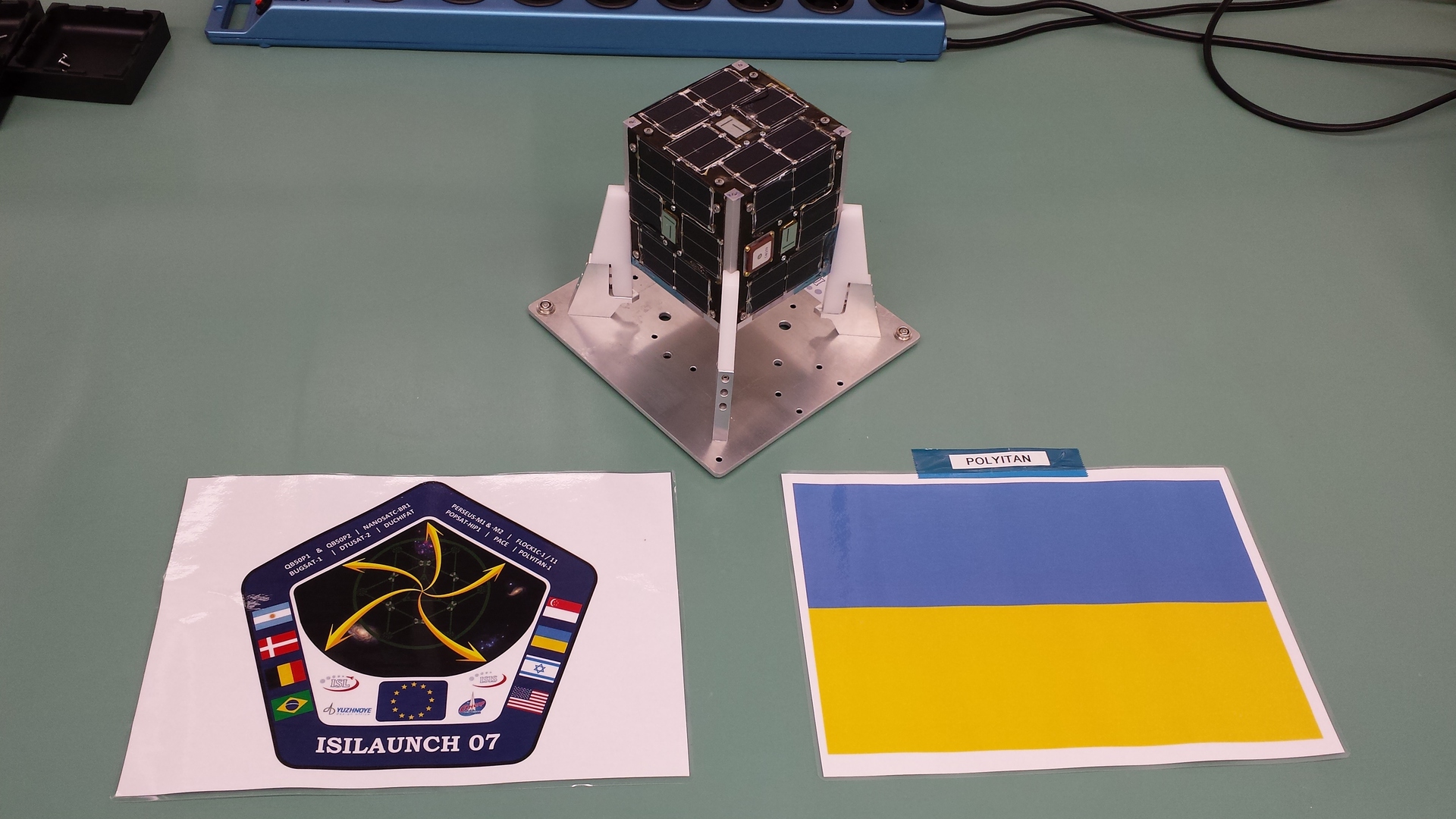
The CubeSat nanosatellite format implies loading into the standardized QuadPack platform for satellite undocking. In the photo place in the platform under our satellite.
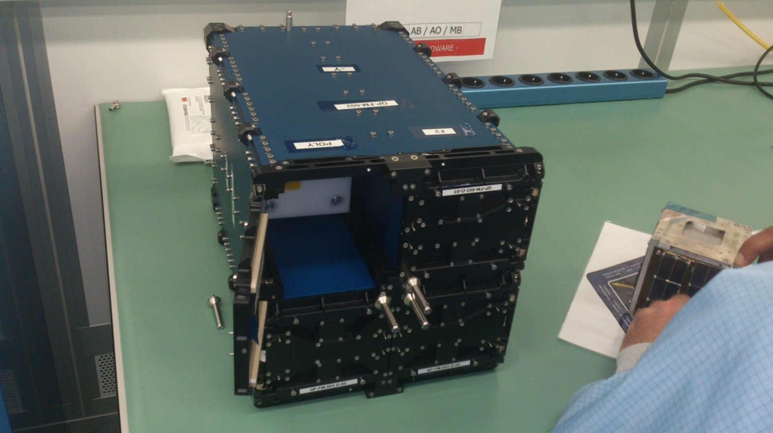
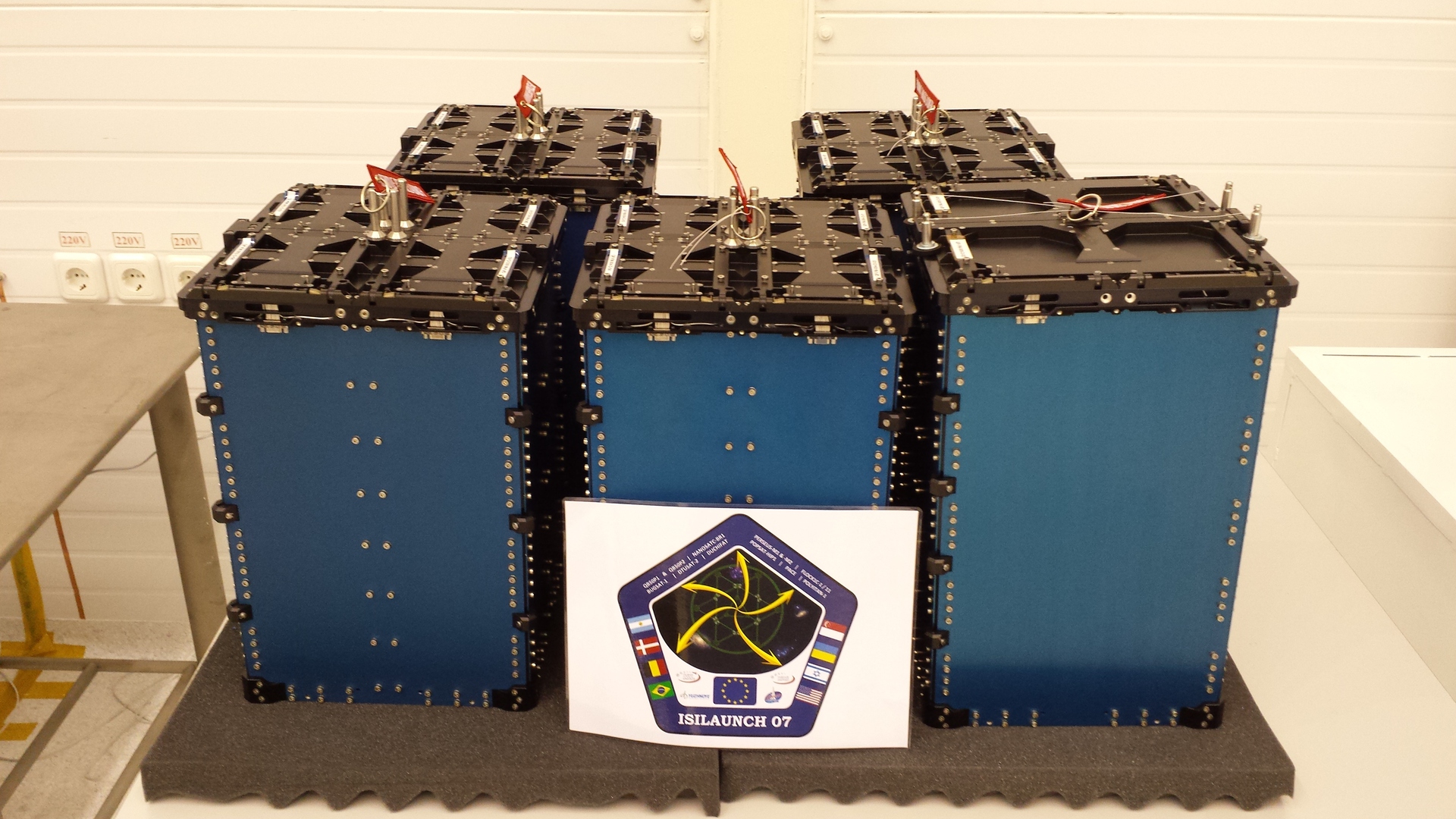
21 CubeSat satellites were loaded at the ISIS office in Delft, Holland.
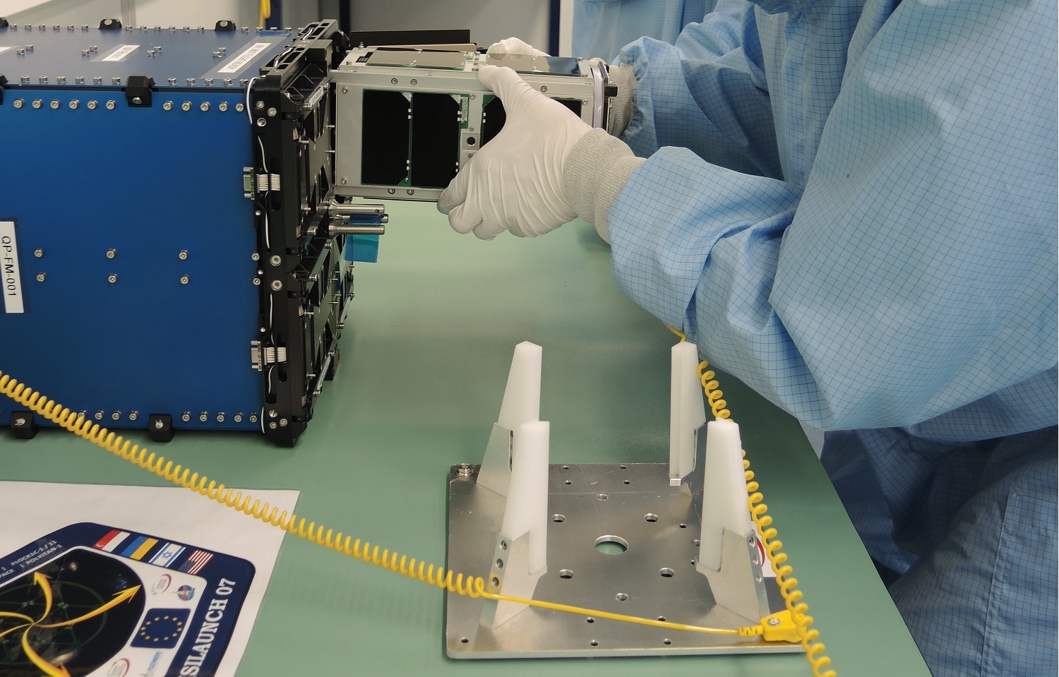
21 satellites of CubeSat format are packed here. After that, they went to Russia for installation on the upper stage of the RS-20 rocket ( Dnepr-1 ).
Installed QuadPack `and on the upper stage.
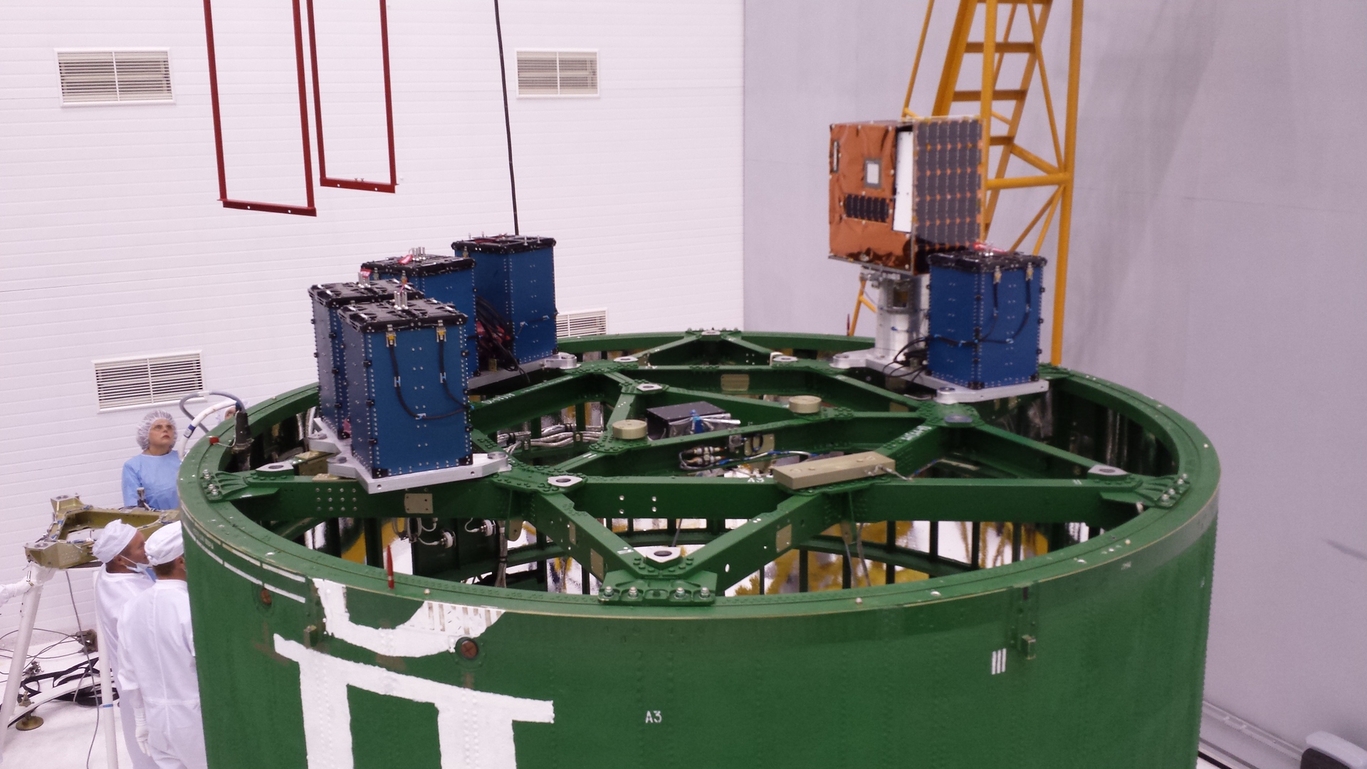
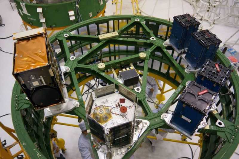
Top view, more satellites:
Flight
On Thursday, June 19, 2014, late at 19:11 UTC, the Dnepr-1 rocket was launched from the Yasny space center (Orenburg region, Russia), carrying 33 spacecraft. Below you can watch a video with the animation of the launch and launch of satellites into orbit for this type of rocket from the Koreans.
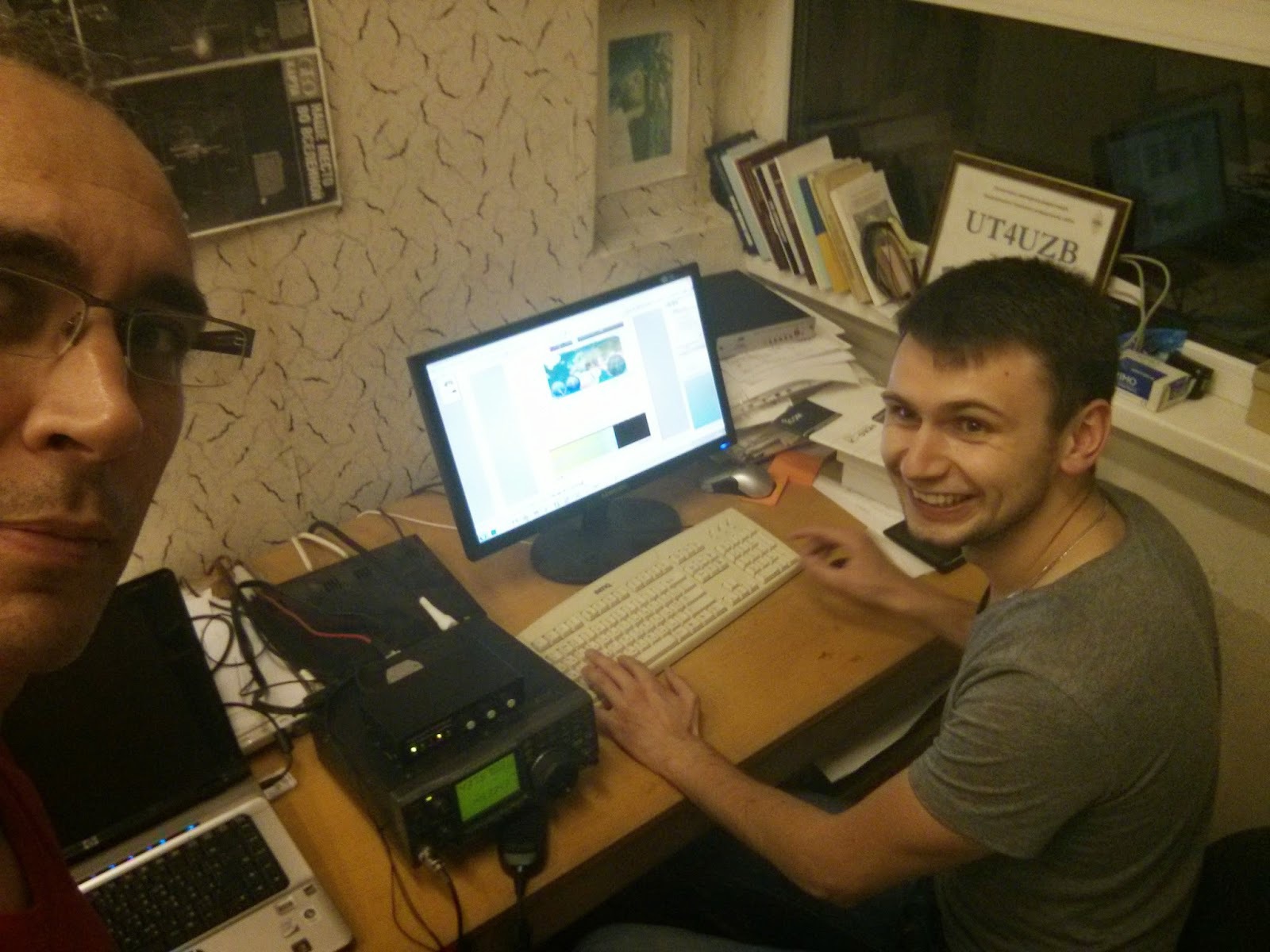
One of the 33 devices is the first Ukrainian university nanosatellite PolyITAN-1, fully developed by staff, KPI students and enthusiasts. The control center - UT4UZB is located at the Thermal Power Engineering Faculty. The main thing is that the satellite was successfully launched into orbit at 7:32 pm and was successfully adopted at a frequency of 437.675 (+ \ - Dopler). Now the CW beacon and telemetry format FSK 9k6. The first who received the signals was Yegor Kasminin UY2RA .
On the seventh floor of the fifth building of the KPI, in anticipation of the satellite flight:
Source: https://habr.com/ru/post/230347/
All Articles