Simple remote control from a robot computer
Preface or why pervert?
Hello, Habrahabr! I sat on the evening of June 11, watched a movie. Unexpectedly, I discovered that an unfamiliar woman had previously written to me with a proposal to make a robot for their new quest. The bottom line is that you need to solve puzzles, explore caches, correctly apply hints, use available things and eventually get keys and open doors ... I was required to make a robot controlled from a computer using a separate program. Furniture had doubts about some problems, for example: will I have time and exactly how to do wireless data transfer (I used to do wireless data transfer only on NXT before)? After weighing all the pros and cons, I agreed. After that, I started thinking about data transfer. Since it was required to make the robot quickly, there was no time to recall and learn, for example, Delphi, so the idea arose to make a module that would be engaged in sending commands. From the computer you just need to send data to the COM port. This method is strange, but the fastest. I want to describe it here. I will also attach 3 programs that will help make a radio-controlled machine.
Assembly of the transmitter and its program.
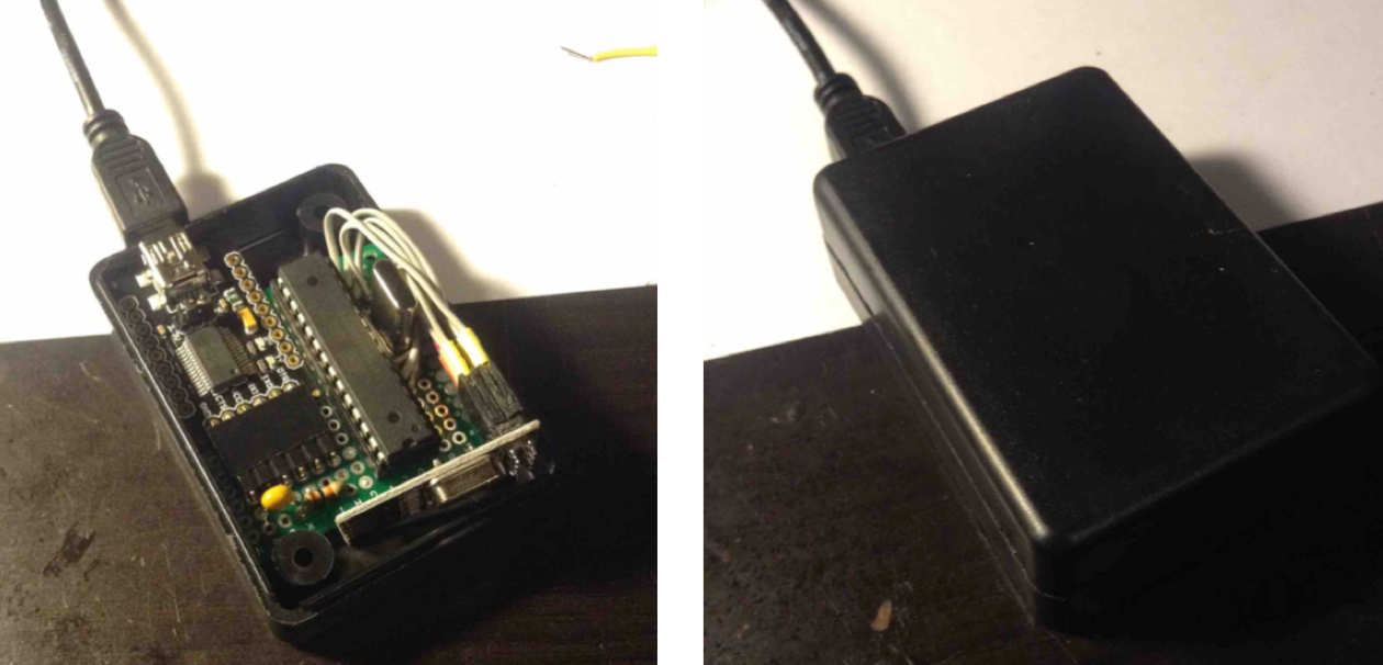
I made a module for a computer from FTDI Basic Breakout 5 / 3.3V from DFrobot, a fairly common ATMEGA 328P-PU microcontroller with an Arduino bootloader and a radio module based on the nRF24L01 chip. In fact, this is just an Arduino Uno with a radio module. It is what it is. The radio module has a feature that I did not immediately notice: the input voltage should be in the range from 3 to 3.6 volts (although supplying 5 volts to it will not kill it, but it will not work), the upper limit of the logical unit is 5V. This means that you do not need a level converter between 3.3V and 5V to connect the radio module to the mega, but you need to install a stabilizer on 3.3V. FTDI has a built-in stabilizer, and from it I fed the radio module.
This is the module itself (inside and in the assembly):
')
The program consists of initialization, start-up message and processing commands from the control program. So it was in my case. The main commands of the Mirf library:
#include <SPI.h>
#include <Mirf.h>
#include <MirfHardwareSpiDriver.h>
#include <MirfSpiDriver.h>
#include <nRF24L01.h>
These libraries are needed for the radio module to work.
Mirf.csnPin = 4 - sets the number of the pin responsible for the "permission to communicate" radio module and MK
Mirf.cePin = 6 - sets the number of the pin responsible for the operation mode of the radio module (receiver / transmitter)
Mirf.spi = & MirfHardwareSpi - customizes the SPI line
Mirf.init () - initializes the radio module
Mirf.payload = 1 - size in bytes of one message (default is 16, maximum 32)
Mirf.channel = 19 - sets the channel (0 - 127, the default is 0)
Mirf.config () - sets the transfer parameters
Mirf.setTADDR ((byte *) "serv1") - switches the radio module to transmitter mode
Mirf.setRADDR ((byte *) "serv1") - switches the radio module to receiver mode
Mirf.send (data) - sends an array of type byte
Mirf.dataReady () - reports the end of the processing of received data
Mirf.getData (data) - write received data to the data array
I attach the program code of the transmitter.
Transmitter program
#include <SPI.h>
#include <Mirf.h>
#include <MirfHardwareSpiDriver.h>
#include <MirfSpiDriver.h>
#include <nRF24L01.h>
char active;
byte data [1];
void setup ()
{
Serial.begin (19200);
Mirf.csnPin = 4;
Mirf.cePin = 6;
Mirf.spi = & MirfHardwareSpi;
Mirf.init ();
Mirf.payload = 1;
Mirf.channel = 19;
Mirf.config ();
Mirf.setTADDR ((byte *) "serv1");
// alarm message about the beginning of work
data [0] = 7;
Mirf.send (data);
delay (200);
}
void loop ()
{
if (Serial.available ()) // If the data is ready to be read
{
active = Serial.read (); // Write data to variable
}
if (active == '2')
{
data [0] = 2;
}
if (active == '3')
{
data [0] = 3;
}
if (active == '4')
{
data [0] = 4;
}
if (active == '5')
{
data [0] = 5;
}
if (active == '6')
{
data [0] = 6;
}
Mirf.send (data); // Send the data
while (Mirf.isSending ()); // Waiting for data to be sent.
}
Management program.
There is one interesting thing - Processing. The syntax is the same as in Arduino, only instead of void loop () there is located void draw (). But it became even more interesting in my situation with the processing Serial library, which allows you to work with the serial port. After reading the lessons on the Spurkfun site, I played with the LED blinking on the arduinka connected to the computer by clicking on the mouse. After that, I wrote a program to control the robot from the keyboard. I attach the control code with the arrows. In it, in principle, there is nothing unusual.
Machine control program
import processing.serial. *;
import cc.arduino. *;
Serial myPort;
PFont f = createFont (“LetterGothicStd-32.vlw”, 24);
void setup ()
{
size (360, 160);
stroke (255);
background (0);
textFont (f);
noCursor ();
String portName = "XXXX"; // Write your port name here
myPort = new Serial (this, portName, 19200);
}
void draw () {
if (keyPressed == false)
{
clear ();
myPort.write ('6');
println ("6");
}
}
void keyPressed ()
{
// 10 - enter
// 32 - probel
// 37/38/39/40 - keys
clear ();
fill (255);
textAlign (CENTER);
// text (keyCode, 180, 80);
switch (keyCode)
{
case 37:
text ("Edem vlevo", 180, 80);
myPort.write ('1');
break;
case 38:
text ("Edem pryamo", 180, 80);
myPort.write ('2');
break;
case 39:
text ("Edem vpravo", 180, 80);
myPort.write ('3');
break;
case 40:
text ("Edem nazad", 180, 80);
myPort.write ('4');
break;
default:
text ("Takoy kommandi net", 180, 80);
myPort.write ('6');
break;
}
}
Receiver program.
The initialization of this program differs from the initialization of the transmitter program by literally one line. Key command in the infinite loop Mirf.getData (data). Next, the resulting command is compared with the numbers, which correspond to any actions of the robot. Well, then the robot acts exactly on commands. I attach the program code of the
Machine programs
#include <SPI.h>
#include <Mirf.h>
#include <MirfHardwareSpiDriver.h>
#include <MirfSpiDriver.h>
#include <nRF24L01.h>
void setup ()
{
Serial.begin (9600);
pinMode (13, OUTPUT); // LED
Mirf.csnPin = 10;
Mirf.cePin = 9;
Mirf.spi = & MirfHardwareSpi;
Mirf.init ();
Mirf.payload = 1;
Mirf.channel = 19;
Mirf.config ();
Mirf.setRADDR ((byte *) "serv1");
}
void loop ()
{
byte data [1];
if (! Mirf.isSending () && Mirf.dataReady ())
{
Mirf.getData (data);
Serial.println (data [0]);
}
switch (data [0])
{
case 1:
motors (-100, 100); // turn left
break;
case 2:
motors (100, 100); // drive straight
break;
case 3:
motors (100, -100); // turn right
break;
case 4:
motors (-100, -100); // go back
break;
default:
motors (0, 0); // standing
break;
}
delay (50);
}
Conclusion
What came of it all:
I made this robot for Claustrophobia . They carry out quests in reality in different cities, and just for one of these quests, the organizers needed a radio-controlled robot sapper. I like it. This, of course, is flawed, because against the background of control with the help of communication tools built into the laptop, but its own, made very quickly and without any problems. I hope this article will help to do something similar, and maybe even more difficult. Here, who wants what.
Source: https://habr.com/ru/post/229605/
All Articles