We analyze the protocol of new sensors Noolite
Hello!
Last week, the company Notechnika released the first two sensors - movement and temperature and humidity for its Noolite light remote control line.
Unfortunately, working with a temperature and humidity sensor using a native USB receiver from Nootechnika is not supported, only through their Ethernet gateway.
')
In our controller for home automation, Wiren Board Smart Home has a built-in universal transceiver at a frequency of 433MHz, with which you can work with many devices. This means that WB Smart Home can work with Noolite devices directly, without the use of Noote USB receivers and transmitters.
However, in order to work with third-party devices, it is usually necessary to start with reverse engineering (ie hacking) of the radio exchange protocol.
The Noolite protocol, used in the lighting control units, we uncovered and disassembled in one of the previous articles .
In this article, we will describe the reverse engineering of the PT111 sensor protocol, updated information about the Noolite protocol device in general, and also show how the work with the sensors looks in WB Smart Home.
Sensors
(as always, thanks to dima117 and thinking-home.ru for very promptly provided devices for experiments.)
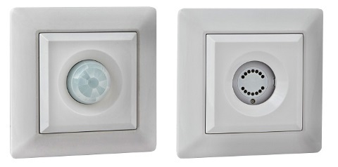
As already mentioned, Notehnika has released two sensors: motion PM111 and temperature / humidity PT111. According to rumors, another temperature sensor is preparing for the exit.
PM111
The PM111 motion sensor has a PIR sensor and a light sensor. The sensor works similarly to Noolite consoles.
After detecting motion, the sensor sends a command to turn on, after a certain time after no movement, a command to turn off.
The sensitivity of the sensor, the duration of the activation and the illumination threshold are adjustable.
Motion sensor with rear cover and protective cap removed (pictures are clickable):

By the way, an interesting trace of the board.
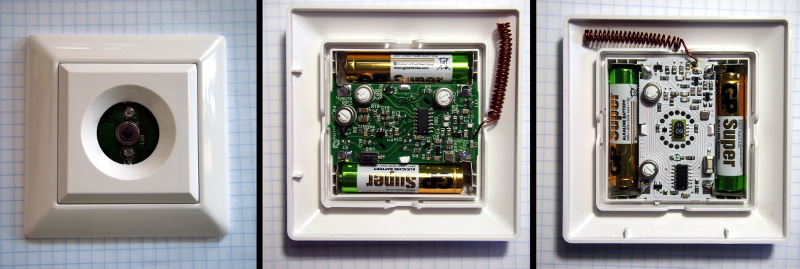
Temperature and humidity sensor PT111

Inside the sensor is used Sensirion SHT10 .
The SHT10 sensor is quite expensive: the wholesale price in Russia is more than 400 rubles , the Chinese sell them for $ 6. Apparently this partly determines the rather high price of the final product.
PT111 is able to work in three modes: actually in the mode of transfer of indications, and also in the modes of the thermostat and a hygrostat.
In the last two modes, the PT111 emulates a conventional Noolite remote control, sending on and off commands when the temperature or humidity passes through a predetermined threshold.
In the thermostat and hygrostat modes, the sending of readings is disabled for some reason.
Unlike the common Oregon Scientific weather sensors, the PT111 sends a data packet only when the temperature or humidity changes, but no more than once per minute.
A button is located on the rear panel of the sensor. When clicked, the PT111 sends bind or unlink commands. When you press a button in sensor mode, the PT111 also immediately sends a data packet if it has changed since the last time.
PT111 protocol
The reverse engineering of the protocol, as always, begins with the collection of package dumps.
As mentioned above, the PT111 has an undocumented feature that is very useful for debugging - the sensor sends readings when you click on the snap button.
The task was somewhat complicated by the fact that we did not have an official Noolite receiver (ethernet gateway) on hand. This means that there was no correct exact temperature and humidity for each data package.
In the process of collecting data, we sent the sensor to the freezer, heated it, etc., to collect as much data as possible.
This is how the data coming from the sensor looks as it is received by the daemon of the Wiren Board Smart Home radio module:
$ mosquitto_sub -v -t /events/wb-homa-rcd/protocols/+ /events/wb-homa-rcd/protocols/raw raw=aaaaaaaaaaaaaaa85559aaa5569a66a6aaa6a960aab3554aad34cd4d554d52c055555555555555555550aaaaad34cd55554cb4a155555a699aaaaa99 /events/wb-homa-rcd/protocols/noo raw=1111110100000011111001001010001000000010000110 fmt=1 cmd=15 flip=1 addr=149f The package presented here is a remote binding package sent by pressing a button on the sensor.
The data packet looks like this (the decoding is already shown here):
/events/wb-homa-rcd/protocols/raw raw=aaaaaaaaaaaaaaa1999aaa9a9aa6a6569555555a699a95aa9a6a4333355535354d4cad2aaaaab4d3352b5534d480000000000000000000000101ffff /events/wb-homa-rcd/protocols/noo addr=149f temp=27.2 lowbat=0 fmt=7 cmd=21 flip=0 humidity=58 raw=10101010000000100010000100010111001111111111111001001010001110000010010001 Source package
aaaaaaaaaaaaaaa1999aaa9a9aa6a6569555555a699a95aa9a6a4333355535354d4cad2aaaaab4d3352b5534d480000000000000000000000101ffff after cutting off the tail and pre-bubble and converting from the Manchester code, it looks like this:
10101010000000100010000100010111001111111111111001001010001110000010010001 “Extended” package format
We divide the message into octets, starting from the end — in Noolite packets, the format and size of the packet are encoded at the end of the packet.
10 10101000 00001000 10000100 01011100 11111111 ( , 16 bit ) 11111001 00101000 () 11100000 () 10010001 We know the values of the last 4 bytes: these are 2 bytes of the block address, a format code byte and a checksum byte.
Unlike previously known packages, this one has a fmt = 7 format code.
There is another difference from packets with commands of ordinary remote controls: the number of first bits.
Here is the package with the usual shutdown command:
#ch:2 off_ch 110000 10011111 10100100 00000000 10000100 # fmt=0 Here before the bytes is a block of 6 bits. The first bit is always one, the next bit (flip) is inverted every transmission (to distinguish duplicates of a command from a new command), then 4 bits go that specify the command code.
In the “extended” format, the first block has 10 bits. The value of the first bit is not clear, for the PT111 sensor it is always equal to one. The next bit is the flip bit. The command in this format has already been allocated 8 bits, not 4. The packet format (extended or normal) is determined by the format code of the last but one byte. The “extended” format, in addition to the PT111 sensor itself (fmt = 7), is also seen in the “switch mode” and “switch color” commands of the Noolite USB transmitter with the fmt = 4 format code.
In the "extended" format, command codes from the normal format are not used, i.e. 0-15 - enters 4 bits; Command codes start at 16.
Depending on the packet format, the checksum (last byte) is also considered differently. The counting function - crc8_maxim - remains the same in both cases, but the first block is processed differently, not a multiple of eight bits:
if cmd < 16: data = chr(((cmd << 1) | flip_bit) << 3) else: data = chr(flip_bit << 7) + chr(cmd) The final package parser looks like this (all the code is in the repository ):
package parser
def parsePacket(self, packet): if len(packet) < 38: return remainder = (len(packet) - 6 ) % 4 if remainder != 0: packet += '0'*(4-remainder) crc = int(packet[-8:][::-1], 2) fmt = int(packet[-16:-8][::-1], 2) addr_lo = int(packet[-32:-24][::-1], 2) addr_hi = int(packet[-24:-16][::-1], 2) addr = (addr_hi << 8) + addr_lo if fmt < 4: sextet_1 = packet[:6] flip_bit = int(sextet_1[1], 2) cmd = int(sextet_1[2:][::-1], 2) args_data = packet[6:-32] else: dectet_1 = packet[:10] flip_bit = int(dectet_1[1], 2) cmd = int(dectet_1[2:][::-1], 2) args_data = packet[10:-32] #~ print "fmt=", fmt, len(args_data) #~ print args_data if fmt == 0: if len(args_data) != 0: return elif fmt == 1: if len(args_data) != 8: return elif fmt == 3: if len(args_data) != 32: return elif fmt == 4: if len(args_data) != 0: return elif fmt == 7: if len(args_data) != 32: return else: return if args_data: args = [int(x[::-1], 2) for x in utils.batch_gen(args_data, 8, align_right=True)] else: args = [] return flip_bit, cmd, addr, fmt, crc, args We retrieve data
(-, ) 10 10101000 () 00001000 10000100 01011100 11111111 ( , 16 bit ) 11111001 00101000 () 11100000 () 10010001 As you can see above, 4 bytes are allocated for the data in the PT111 packet.
Let's see how this data changes from sending to sending (4 bytes of data are allocated):
10 10101000 { 00101000 10000100 01010100 11111111 } 11111001 00101000 11100000 10000000 10 10101000 { 00001000 10000100 01001100 11111111 } 11111001 00101000 11100000 11101101 11 10101000 { 11000100 10000100 10000010 11111111 } 11111001 00101000 11100000 01010110 10 10101000 { 01011000 10000100 10111100 11111111 } 11111001 00101000 11100000 11001010 11 10101000 { 00011000 10000100 01011100 11111111 } 11111001 00101000 11100000 10101011 11 10101000 { 01101000 10000100 11110100 11111111 } 11111001 00101000 11100000 00100000 We see that the fourth byte of data in all parcels is 0xFF (0b11111111). Apparently he is reserved.
What is the third data byte? It is likely that this is a whole 8-bit moisture value: the values decoded in this way are adequate. Moreover, the value of this byte never exceeds 100 (0x64), which can be checked by setting the maximum humidity on the sensor (for example, breathing into the sensor for a couple of minutes).
With a strong local heating of the air with a soldering iron, the value of the byte drops to 5-10, which seems to be true.
The first byte is constantly changing with various manipulations with the sensor - apparently it is somehow responsible for the temperature.
The second byte does not seem to change. We will check if the status of a discharged battery is encoded here (judging by the description, the sensor broadcasts a warning about this by radio).
Close the contacts of one battery with a thin wire to reduce the voltage:
( ) 10 10101000 11000000 { 10000100 } 00111100 11111111 11111001 00101000 11100000 10010101 ( ) 10 10101000 11100000 { 10000101 } 00100110 11111111 11111001 00101000 11100000 00111000 We see that the low bit of this byte has changed. It encodes the battery charge status.
What could be the remaining bits of the second byte? For example, there may be separately stored temperature sign, as in the sensors Oregon Scientific.
Cool the sensor:
11 10101000 00110000 { 10000100 } 00001100 11111111 11111001 00101000 11100000 1110011 # 12, 33 ( ) 10 10101000 10011000 { 00000100 } 01101100 11111111 11111001 00101000 11100000 1100101 (25) 10 10101000 00111000 { 00000100 } 11011100 11111111 11111001 00101000 11100000 0110111 (28) 11 10101000 10111000 { 00000100 } 11110100 11111111 11111001 00101000 11100000 10100001 ( -18C, 1111) 11 10101000 01111010 { 11110100 } 11000010 11111111 11111001 00101000 11100000 1000100 (3934 = -16.2C) ( , ) 10 10101000 00101010 { 11110100 } 11011100 11111111 11111001 00101000 11100000 00100110 (-17.2C) 10 10101000 10110001 { 11110100 } 01111100 11111111 11111001 00101000 11100000 10001011 (-11.5C) 10 10101000 01000011 { 11110100 } 11100010 11111111 11111001 00101000 11100000 01010011 (-6.2C) 10 10101000 11000111 { 11110100 } 00101010 11111111 11111001 00101000 11100000 01010100 (-2.9C) 11 10101000 00001111 { 11110100 } 11011010 11111111 11111001 00101000 11100000 00101010 (-1.6C) ( ? 1111 => 0000) 11 10101000 11100100 { 00000100 } 01111010 11111111 11111001 00101000 11100000 01011101 (3.9C) 10 10101000 11000010 { 00000100 } 10000110 11111111 11111001 00101000 11100000 00000100 Additionally, we warm the sensor:
10 10101000 11000101 { 01000100 } 11000000 11111111 11111001 00101000 11100000 1100011 # 67.5 10 10101000 00100110 { 01000100 } 01000000 11111111 11111001 00101000 11100000 1011001 # We see that the first 4 bits of the second byte behave as follows:
- When the temperature decreases, the value first changes from 0b0001 to 0b0000 (the order of bits is the reverse)
- After freezing to -18, the value becomes 0b1111
- When heated at some point, the value changes from 0b1111 to 0b0000
- When strongly heated above room temperature, the value changes from 0b0001 to 0b0002
So the simplest explanation that comes to mind is that a piece of signed temperature value is stored in the first four bits.
We glue these four bits with 8 bits from the first byte and get the 12-bit signed value. Decoding results make it possible to understand that this is a 12-bit signed value of the temperature in tens of degrees Celsius.
Decoding example:
1) bytes 1-2 = 11100100 00000100 0000 00100111 (bin) = 39 (dec) = 3.9C 2) bytes 1-2 = 00101010 11110100 1111 01010100 (bin) = 3924 (dec). 3924 - 0x1000 = -172 = -17.2C Total decoding temperature code:
temp = ((args[1] & 0x0F) << 8) + args[0] if temp > 0x7ff: temp = temp - 0x1000 temp = temp * 0.1 Total data format is PT111
temp/hum: flip, 2 bit --> 10 10101000 11100000 10000101 00100110 11111111 11111001 00101000 11100000 00111000 cmd 8 bit ---^ | | ^ ^ ^ ^ addr_lo addr_hi fmt crc temperature, signed, 0.1C --> |-- 12 bit -| | | | | unknown, 3bit, 0b010 ------->---------------- | | | bat low, 1bit ------------->------------------ | | humidity, 8 bit ------------->----------------------- | unknown, 8 bit, always 0xFF so far -------->------------------ WB Smart Home
In the native WB Smart Home web interface, the sensors look something like this:

The final code to work with Noolite in our repository .
Advertising
WB Smart Home controller is available for sale on our website .
We are also looking for C / C ++ / Python programmers (Linux)
(better all from the list at once), develop software for our hardware for home and industrial automation.
The work includes including the addition of support in WB Smart Home for new external wired and wireless devices, such as those described in this article.
Geography: Moscow - Dolgoprudny, distant work and part-time employment are also considered.
You can write to info+hr3@contactless.ru.
The work includes including the addition of support in WB Smart Home for new external wired and wireless devices, such as those described in this article.
Geography: Moscow - Dolgoprudny, distant work and part-time employment are also considered.
You can write to info+hr3@contactless.ru.
Source: https://habr.com/ru/post/229469/
All Articles