Reducing the operating voltage of the processor, or tuning Enhanced Intel SpeedStep
Modern desktop and (especially) mobile processors use a number of energy-saving technologies: ODCM, CxE, EIST, etc. Today we will be interested in, perhaps, the highest level of them: flexible control of the frequency and voltage of the processor core during operation - Cool 'n 'Quiet, PowerNow! from AMD and Enhanced SpeedStep (EIST) from Intel.
Most often, a user of a computer or laptop can simply turn on (tick) support for a particular technology in the BIOS and / or the operating system — no tweaking is usually provided, although, as practice shows, it can be very useful. In this article I will talk about how you can control the operating voltage of the processor core from the operating system (using the example of Intel Pentium M and FreeBSD), and why this may be needed.
Despite the large number of manuals, it’s rare to find a detailed description of the Enhanced SpeedStep technology from the point of view of the operating system (and not the end user), especially in Russian, so much of the article is devoted to implementation details and is to some extent theoretical in nature.
')
I hope the article will be useful not only to FreeBSD users: we will also touch on GNU / Linux, Windows and Mac OS X a bit. However, in this case, a specific operating system is of secondary importance.
Last year I upgraded the processor in my old laptop: I installed the Pentium M 780 instead of the standard 735, finished it to the maximum, so to speak. The laptop began to warm up more under load (due to the heat release increased by 10 W); I didn’t pay much attention to this (unless I cleaned and smeared the cooler just in case), but one day, during a long compilation, the computer ... just turned off (the temperature did reach a critical hundred degrees). I brought the value of the system variable
Usually, a change in the nominal voltage implies its increase in order to ensure stable operation of the processor during acceleration (i.e., at a higher frequency). Roughly speaking, each voltage value corresponds to a certain range of frequencies at which it can work, and the task of the overclocker is to find the maximum frequency at which the processor is not yet “buggy”. In our case, the task is in a certain sense symmetrical: for a known frequency (more precisely, as we will soon find out, a set of frequencies) to find the lowest voltage that ensures stable operation of the CPU. But I do not want to lower the working frequency in order not to lose in performance - the laptop is already far from being top-notch. In addition, lower voltage is more profitable .
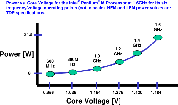
As you know, the processor's heat dissipation is proportional to its capacity, frequency, and voltage square (who cares why this is the case, they can try to derive the dependency on their own, considering the processor as a set of elementary CMOS inverters (logical negatives), or refer to the links: one , two , three ).
Modern mobile processors can consume up to 50-70 watts, which eventually dissipate into heat. This is a lot (remember incandescent bulbs), especially for a laptop that in offline mode under load will “eat” the battery like that pig oranges. In conditions of limited space, the heat will most likely have to be removed actively, and this means additional energy consumption for the rotation of the fan of the cooler (possibly several).
Naturally, this situation did not suit anyone, and processor manufacturers began to think about how to optimize power consumption (and, accordingly, heat transfer), and at the same time prevent the processor from overheating. I recommend to those interested in reading a number of remarkable articles by Dmitriy Besedin, and in the meantime I will proceed directly to the point.
For the first time, SpeedStep technology (version 1.1) appeared in the second generation of third Pentiums (Coppermine mobile for notebooks produced according to the .18 micron process technology, 2000), which could switch between high and low depending on the load or power source of the computer frequencies due to a variable multiplier. In economy mode, the processor consumed about half the energy.
With the transition to the .13 micron technical process, the technology gets the version number 2.1 and becomes “enhanced” (enhanced) - now the processor is able to lower not only the frequency, but also the voltage. Version 2.2 is an adaptation for the NetBurst architecture, and by the third version (Centrino platform) the technology will be officially called Enhanced Intel SpeedStep (EIST).
Version 3.1 (2003) is first used in the first and second generation Pentium M processors (Banias and Dothan cores). The frequency varied (at first - only switched between two values) from 40% to 100% of the baseline, in 100 MHz increments (for Banias) or 133 MHz (for Dothan, our case). At the same time, Intel introduces dynamic management of second-level cache capacity (L2), which allows for even better optimization of power consumption. Version 3.2 (Enhanced EIST) - adaptation for multi-core processors with shared L2 cache. (A small FAQ from Intel on technology SpeedStep.)
Now, instead of blindly following the numerous howto and tutorials, download the pdf and try to understand the principle of the EST (I will continue to use this abbreviation, because it is more universal and shorter).
So, EST allows you to control the performance and power consumption of the processor, and dynamically , during its operation. Unlike earlier implementations, which required hardware support (in the chipset) to change the operating parameters of the processor, EST allows software , i.e. by means of the BIOS or the operating system, change the multiplier (ratio of processor frequency to bus frequency) and core voltage (V cc ) depending on the load, type of computer power supply, CPU temperature conditions and / or operating system settings (policies).
During operation, the processor is in one of several power states: T (throttle), S (sleep), C (idle), P (performance), switching between them according to certain rules (p. 386 of the ACPI 5.0 specification ).

Each processor present in the system must be described in the DSDT table, most often in the
EST controls the operation of the processor in the P-state (P-state), and they will interest us. For example, the Pentium M supports six P-states (see Fig. 1.1 and Tab. 1.6 pdf), which differ in voltage and frequency:
In the general case, when the processor is not known in advance, the only more or less reliable (and recommended by Intel) method of working with it is ACPI. You can interact with a specific processor directly, bypassing ACPI, through the Model-Specific Register (MSR) registers, including directly from the command line: starting from version 7.2, the
To find out if your processor supports EST, you can look at the 16th bit in the
A similar command for GNU / Linux (the msr-tools package is required):
The transition between states occurs when writing to the register
Let's try to start reading the current
It follows from the documentation that the current state is encoded in the lower 16 bits (if you execute the command several times, their value may change - this means that the EST is working). If you look closely at the other bits, they are also clearly not rubbish. Googling, you can find out what they mean.
Data read from
Three 16-bit fields are the so-called Performance State Values (PSV), we will consider their structure below: the current PSV value, the maximum (depending on the processor) and the value at the start of the system (when turned on). The current value (curr_psv) obviously changes when the operation mode changes, the maximum (max_psv) usually remains constant, the starting value (init_psv) does not change: as a rule, it is equal to the maximum value for desktops and servers, but the minimum for mobile CPUs. The minimum factor (min_mult) for Intel processors is almost always six. The status field contains the value of some flags, for example, upon the occurrence of an EST or THERM event (that is, at the moment the P-state changes or the processor overheats, respectively).
Now that we know the assignment of all 64 bits of the
It is very important to know and understand what PSV is, because it is in this form that the modes of operation of the processor are set.
Dynamic FSB frequency switching indicates to skip every second FSB clock, i.e. double the operating frequency; This feature was first implemented in Core 2 Duo processors (Merom core) and does not concern us, as does the Non-integer bus ratio - a special mode supported by some processors, which allows, as the name implies, to more finely control their frequency.
EST technology itself has two fields: frequency identifiers (Frequency Identifier, Fid), which is numerically equal to the multiplier, and voltages (Voltage Identifier, Vid), which corresponds to the voltage level (it is usually the least documented).
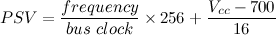
Intel is very reluctant to disclose information (usually an NDA is required to sign) about how the voltage identifier is encoded for each processor. But for most popular CPUs, fortunately, this formula is well known; in particular, for our Pentium M (and many others): V cc = Vid 0 + (Vid × V step ), where V cc is the current (real) voltage, Vid 0 is the base voltage (when Vid == 0), V step - step. Table for some popular processors (all values are in millivolts):
The multiplier (i.e., Fid) is written in PSV shifted 8 bits to the left, the lower six bits are occupied by Vid. Since in our case, the remaining bits can be neglected, then PSV, processor frequency, system bus and physical voltage are related by a simple formula (for Pentium M):
Now consider the control register (
IDA (Intel Dynamic Acceleration) disengage bits allows you to temporarily disable adaptive (frequency) frequency control on Intel Core 2 Duo T7700 and later processors - again, we are not interested. The lower 16 bits (PSV) is the mode in which we “ask” the processor to switch.
The
Thus, each P-state is characterized by some core operating frequency, maximum power dissipation, transit delays (actually, the transition time between states during which the CPU and memory are unavailable), finally, the most interesting: PSV, which corresponds to this state and which must be written to
The EST driver of the operating system may “know” about some processors, i.e. will manage them without ACPI support. But this is rare, especially nowadays (although for Linux undervolting, somewhere before version 2.6.20, it was necessary to patch the tables in the driver, and back in 2011 this method was quite common ).
It is worth noting that the EST driver can work even in the absence of the
Now, when we know 1) the assignment of all bits in the right MSR words, 2) how exactly PSV is encoded for our processor, and 3) where in DSDT to search for the necessary settings, it's time to create a table of frequencies and voltages by default . Let's take the DSDT and look for the
So, we know the default Vid for each P-level: 43, 37, 32, 28, 23, 18, which corresponds to voltages from 1388 mV to 988 mV. The essence of undervolting is that these voltages are probably somewhat higher than is really necessary for the stable operation of the processor. Let's try to determine the "boundaries of what is permitted."
I wrote a simple shell script for this, which gradually lowers the Vid and performs an uncomplicated loop (the
Now that we have empirically determined the minimum safe voltages, it is interesting to compare them with the original ones:
Even lowering the maximum voltage by 15% yielded quite tangible results: a prolonged load not only does not lead to more processor overheating and emergency shutdown, the temperature in general now almost never exceeds 80 ° C. The predicted battery life in the “office” mode, judging by the
Now we need to make sure that the settings are applied automatically. You can, for example, modify the
If we get PSV values via ACPI, then it is most logical to change the
Compile the new AML file (ACPI bytecode) and modify / boot / loader.conf so that FreeBSD loads our modified DSDT instead of the default one:
Here, in general, and all. The only thing, do not forget to comment out these two lines in /
Even if you are not going to lower the nominal voltages, the ability to tune the management of processor states (not just P-states) can be useful. After all, it is often the case that the “curve” BIOS fills the tables incorrectly, not completely, or does not fill them at all (for example, because the Tseleron does not support EST, and the manufacturer does not officially provide for its replacement). In this case, you have to do all the work yourself . Note that adding only the
In truth, at first I thought it would be enough for me to read the Gentoo Undervolting Guide and just adapt it for FreeBSD. This was not so easy, because the document turned out to be extremely confused (which is actually strange for the Gentoo Wiki). Unfortunately, I did not find anything similar on their new website, I had to be content with the old copy; and although I understand that this guide has lost much of its relevance, I still criticize it a bit. :-)
For some reason, immediately,without a declaration of war, I am offered a patch kernel (in FreeBSD, for a moment, we don’t have any system code at allit was not necessary to modify). To hammer inside the driver or to write in some init scripts the values of some “safe” voltages, unintelligibly obtained by whom and how, from a special table (in which the Pentium M 780 is mockingly represented as a string consisting of only question marks). Follow the tips, among which are written by people who clearly do not understand what they are talking about. And most importantly, it is completely unclear why and how exactly these magical replacements of some numbers for others work; there is no suggested way to “touch” EST, before patching and rebuilding the kernel, the MSR registers and the work with them from the command line are never mentioned. Modification of ACPI tables is not considered as an alternative and more preferred option.
ThinkWiki tutorial a little better(and newer), but not by much. The ArchWiki page is even more concise . This line delivers especially:
And so Lost's “4, 8, 15, 16, 23, 42” are asked (albeit in the reverse order, which spoils the joke somewhat).
Perhaps the most sensible description of the entire process for Linux by Pat Erley, the link to which I gave above.
There is no particular point in talking about Windows: there is both software and discussions on the forums, so I’ll just leave a couple of links here .
Makos rather closely interacts with (and relies on correct operation) ACPI, and modification of the tables is one of the main methods for setting it up for a specific hardware. So the first thing that comes to mind - just sdampit and patch her the DSDT . Alternative method:
Another "wonderful" utility (fortunately, already outdated) offers to buy for $ 10 the opportunity to change the voltage and frequency. :-)
FreeBSD: , ; . Linux ArchWiki.
, , , — ( , ) (, Comic Sans).
Most often, a user of a computer or laptop can simply turn on (tick) support for a particular technology in the BIOS and / or the operating system — no tweaking is usually provided, although, as practice shows, it can be very useful. In this article I will talk about how you can control the operating voltage of the processor core from the operating system (using the example of Intel Pentium M and FreeBSD), and why this may be needed.
Despite the large number of manuals, it’s rare to find a detailed description of the Enhanced SpeedStep technology from the point of view of the operating system (and not the end user), especially in Russian, so much of the article is devoted to implementation details and is to some extent theoretical in nature.
')
I hope the article will be useful not only to FreeBSD users: we will also touch on GNU / Linux, Windows and Mac OS X a bit. However, in this case, a specific operating system is of secondary importance.
Foreword
Last year I upgraded the processor in my old laptop: I installed the Pentium M 780 instead of the standard 735, finished it to the maximum, so to speak. The laptop began to warm up more under load (due to the heat release increased by 10 W); I didn’t pay much attention to this (unless I cleaned and smeared the cooler just in case), but one day, during a long compilation, the computer ... just turned off (the temperature did reach a critical hundred degrees). I brought the value of the system variable
hw.acpi.thermal.tz0.temperature to tray, in order to monitor the temperature and, if anything, to interrupt the “hard” task in time. But after some time I lost my vigilance (the temperature always remained within the normal range), and everything repeated. At that moment, I decided that I no longer want to constantly fear emergency shutdown during a long CPU load and keep my hand on Ctrl-C or force the processor.Usually, a change in the nominal voltage implies its increase in order to ensure stable operation of the processor during acceleration (i.e., at a higher frequency). Roughly speaking, each voltage value corresponds to a certain range of frequencies at which it can work, and the task of the overclocker is to find the maximum frequency at which the processor is not yet “buggy”. In our case, the task is in a certain sense symmetrical: for a known frequency (more precisely, as we will soon find out, a set of frequencies) to find the lowest voltage that ensures stable operation of the CPU. But I do not want to lower the working frequency in order not to lose in performance - the laptop is already far from being top-notch. In addition, lower voltage is more profitable .
Some theory
As you know, the processor's heat dissipation is proportional to its capacity, frequency, and voltage square (who cares why this is the case, they can try to derive the dependency on their own, considering the processor as a set of elementary CMOS inverters (logical negatives), or refer to the links: one , two , three ).
Modern mobile processors can consume up to 50-70 watts, which eventually dissipate into heat. This is a lot (remember incandescent bulbs), especially for a laptop that in offline mode under load will “eat” the battery like that pig oranges. In conditions of limited space, the heat will most likely have to be removed actively, and this means additional energy consumption for the rotation of the fan of the cooler (possibly several).
Naturally, this situation did not suit anyone, and processor manufacturers began to think about how to optimize power consumption (and, accordingly, heat transfer), and at the same time prevent the processor from overheating. I recommend to those interested in reading a number of remarkable articles by Dmitriy Besedin, and in the meantime I will proceed directly to the point.
A bit of history
For the first time, SpeedStep technology (version 1.1) appeared in the second generation of third Pentiums (Coppermine mobile for notebooks produced according to the .18 micron process technology, 2000), which could switch between high and low depending on the load or power source of the computer frequencies due to a variable multiplier. In economy mode, the processor consumed about half the energy.
With the transition to the .13 micron technical process, the technology gets the version number 2.1 and becomes “enhanced” (enhanced) - now the processor is able to lower not only the frequency, but also the voltage. Version 2.2 is an adaptation for the NetBurst architecture, and by the third version (Centrino platform) the technology will be officially called Enhanced Intel SpeedStep (EIST).
Version 3.1 (2003) is first used in the first and second generation Pentium M processors (Banias and Dothan cores). The frequency varied (at first - only switched between two values) from 40% to 100% of the baseline, in 100 MHz increments (for Banias) or 133 MHz (for Dothan, our case). At the same time, Intel introduces dynamic management of second-level cache capacity (L2), which allows for even better optimization of power consumption. Version 3.2 (Enhanced EIST) - adaptation for multi-core processors with shared L2 cache. (A small FAQ from Intel on technology SpeedStep.)
Now, instead of blindly following the numerous howto and tutorials, download the pdf and try to understand the principle of the EST (I will continue to use this abbreviation, because it is more universal and shorter).
How does the est
So, EST allows you to control the performance and power consumption of the processor, and dynamically , during its operation. Unlike earlier implementations, which required hardware support (in the chipset) to change the operating parameters of the processor, EST allows software , i.e. by means of the BIOS or the operating system, change the multiplier (ratio of processor frequency to bus frequency) and core voltage (V cc ) depending on the load, type of computer power supply, CPU temperature conditions and / or operating system settings (policies).
During operation, the processor is in one of several power states: T (throttle), S (sleep), C (idle), P (performance), switching between them according to certain rules (p. 386 of the ACPI 5.0 specification ).
Each processor present in the system must be described in the DSDT table, most often in the
\_PR , and usually provides a number of methods through which it interacts with the operating system (driver PM) and which describe the capabilities of the processor ( _PDC , _PPC ) , supported states ( _CST , _TSS , _PSS ) and their management ( _PTC , _PCT ). The required values for each CPU (if it is included in the so-called CPU support package) are determined by the motherboard BIOS, which fills the corresponding tables and ACPI methods (p. 11 pdf) when the machine boots.EST controls the operation of the processor in the P-state (P-state), and they will interest us. For example, the Pentium M supports six P-states (see Fig. 1.1 and Tab. 1.6 pdf), which differ in voltage and frequency:
In the general case, when the processor is not known in advance, the only more or less reliable (and recommended by Intel) method of working with it is ACPI. You can interact with a specific processor directly, bypassing ACPI, through the Model-Specific Register (MSR) registers, including directly from the command line: starting from version 7.2, the
cpucontrol(8) utility is used for this in FreeBSD.To find out if your processor supports EST, you can look at the 16th bit in the
IA_32_MISC_ENABLE (0x1A0) register, it should be set: # kldload cpuctl # cpucontrol -m 0x1a0 /dev/cpuctl0 | (read _ msr hi lo ; echo $((lo >> 16 & 1))) 1 A similar command for GNU / Linux (the msr-tools package is required):
# modprobe msr # echo $((`rdmsr -c 0x1a0` >> 16 & 1)) 1 The transition between states occurs when writing to the register
IA32_PERF_CTL (0x199). You can find out the current operation mode by reading the register IA32_PERF_STATUS (0x198), which is dynamically updated (tab. 1.4 pdf'ki). In the future, the prefix IA32_ I will omit for brevity.Let's try to start reading the current
PERF_STATUS value: # cpucontrol -m 0x198 /dev/cpuctl0 MSR 0x198: 0x0612112b 0x06000c20 It follows from the documentation that the current state is encoded in the lower 16 bits (if you execute the command several times, their value may change - this means that the EST is working). If you look closely at the other bits, they are also clearly not rubbish. Googling, you can find out what they mean.
PERF_STATUS register structure
Data read from
PERF_STATUS is represented by the following structure (we PERF_STATUS that the data is stored as little-endian): struct msr_perf_status { unsigned curr_psv : 16; /* Current PSV */ unsigned status : 8; /* Status flags */ unsigned min_mult : 8; /* Minimum multiplier */ unsigned max_psv : 16; /* Maximum PSV */ unsigned init_psv : 16; /* Power-on PSV */ }; Three 16-bit fields are the so-called Performance State Values (PSV), we will consider their structure below: the current PSV value, the maximum (depending on the processor) and the value at the start of the system (when turned on). The current value (curr_psv) obviously changes when the operation mode changes, the maximum (max_psv) usually remains constant, the starting value (init_psv) does not change: as a rule, it is equal to the maximum value for desktops and servers, but the minimum for mobile CPUs. The minimum factor (min_mult) for Intel processors is almost always six. The status field contains the value of some flags, for example, upon the occurrence of an EST or THERM event (that is, at the moment the P-state changes or the processor overheats, respectively).
Now that we know the assignment of all 64 bits of the
PERF_STATUS register, we can decipher the word read above: 0x 0612 112b 0x 06 00 0c20 ⇒ PSV at start 0x0612, maximum value 0x112b, minimum factor 6 (as expected), the flags are reset, the current value PSV = 0x0c20. What exactly do these 16 bits mean?Performance State Value (PSV) structure
It is very important to know and understand what PSV is, because it is in this form that the modes of operation of the processor are set.
struct psv { unsigned vid : 6; /* Voltage Identifier */ unsigned _reserved1 : 2; unsigned freq : 5; /* Frequency Identifier */ unsigned _reserved2 : 1; unsigned nibr : 1; /* Non-integer bus ratio */ unsigned slfm : 1; /* Dynamic FSB frequency (Super-LFM) */ }; Dynamic FSB frequency switching indicates to skip every second FSB clock, i.e. double the operating frequency; This feature was first implemented in Core 2 Duo processors (Merom core) and does not concern us, as does the Non-integer bus ratio - a special mode supported by some processors, which allows, as the name implies, to more finely control their frequency.
EST technology itself has two fields: frequency identifiers (Frequency Identifier, Fid), which is numerically equal to the multiplier, and voltages (Voltage Identifier, Vid), which corresponds to the voltage level (it is usually the least documented).
Voltage Identifier
Intel is very reluctant to disclose information (usually an NDA is required to sign) about how the voltage identifier is encoded for each processor. But for most popular CPUs, fortunately, this formula is well known; in particular, for our Pentium M (and many others): V cc = Vid 0 + (Vid × V step ), where V cc is the current (real) voltage, Vid 0 is the base voltage (when Vid == 0), V step - step. Table for some popular processors (all values are in millivolts):
| CPU | Vid 0 | V step | V boot | V min | V max |
|---|---|---|---|---|---|
| Pentium M | 700.0 | 16.0 | xxxx, x | xxx, x | xxxx, x |
| E6000, E4000 | 825.0 | 12.5 | 1100.0 | 850.0 | 1500.0 |
| E8000, E7000 | 825.0 | 12.5 | 1100.0 | 850.0 | 1362.5 |
| X9000 | 712.5 | 12.5 | 1200.0 | 800.0 | 1325.0 |
| T9000 | 712.5 | 12.5 | 1200.0 | 750.0 | 1300.0 |
| P9000, P8000 | 712.5 | 12.5 | 1200.0 | 750.0 | 1300.0 |
| Q9000D, Q8000D | 825.0 | 12.5 | 1100.0 | 850.0 | 1362.5 |
| Q9000M | 712.5 | 12.5 | 1200.0 | 850.0 | 1300.0 |
Now consider the control register (
PERF_CTL ). Writing to it should be done as follows: first, the current value is read (the 64-bit word entirely), the necessary bits are changed in it, and written back to the register (the so-called read-modify-write).PERF_CTL register structure
struct msr_perf_ctl { unsigned psv : 16; /* Requested PSV */ unsigned _reserved1 : 16; unsigned ida_diseng : 1; /* IDA disengage */ unsigned _reserved2 : 31; }; IDA (Intel Dynamic Acceleration) disengage bits allows you to temporarily disable adaptive (frequency) frequency control on Intel Core 2 Duo T7700 and later processors - again, we are not interested. The lower 16 bits (PSV) is the mode in which we “ask” the processor to switch.
_PSS table
The
_PSS table is an array of states ( Package in ACPI terminology) or a method that returns such an array; each state (P-state) in turn is defined by the following structure (p. 409 of the ACPI specification): struct Pstate { unsigned CoreFrequency; /* Core CPU operating frequency, MHz */ unsigned Power; /* Maximum power dissipation, mW */ unsigned Latency; /* Worst-case latency of CPU unavailability during transition, µs */ unsigned BusMasterLatency; /* Worst-case latency while Bus Masters are unable to access memory, µs */ unsigned Control; /* Value to be written to the PERF_CTL to switch to this state */ unsigned Status; /* Value (should be equal to the one read from PERF_STATUS) */ }; Thus, each P-state is characterized by some core operating frequency, maximum power dissipation, transit delays (actually, the transition time between states during which the CPU and memory are unavailable), finally, the most interesting: PSV, which corresponds to this state and which must be written to
PERF_CTL in order to go to this state (Control). To verify that the processor has successfully transitioned to a new state, you need to read the register PERF_STATUS and compare it with the value recorded in the Status field.The EST driver of the operating system may “know” about some processors, i.e. will manage them without ACPI support. But this is rare, especially nowadays (although for Linux undervolting, somewhere before version 2.6.20, it was necessary to patch the tables in the driver, and back in 2011 this method was quite common ).
It is worth noting that the EST driver can work even in the absence of the
_PSS table and an unknown processor, since the maximum and minimum values can be PERF_STATUS from PERF_STATUS (in this case, obviously, the number of P-states degenerates into two).Enough theory. What to do with it all?
Now, when we know 1) the assignment of all bits in the right MSR words, 2) how exactly PSV is encoded for our processor, and 3) where in DSDT to search for the necessary settings, it's time to create a table of frequencies and voltages by default . Let's take the DSDT and look for the
_PSS table _PSS . For the Pentium M 780, it should look something like this:Default _PSS values
Name (_PSS, Package (0x06) { // 6 (P-states) Package (0x06) { 0x000008DB, // 2267 MHz (cf. Fid × FSB clock) 0x00006978, // 27000 mW 0x0000000A, // 10 µs ( ) 0x0000000A, // 10 µs 0x0000112B, // 0x11 = 17 (, Fid), 0x2b = 43 (Vid) 0x0000112B }, Package (0x06) { 0x0000074B, // 1867 MHz (82% ) 0x000059D8, // 23000 mW 0x0000000A, 0x0000000A, 0x00000E25, // Fid = 14, Vid = 37 0x00000E25 }, Package (0x06) { 0x00000640, // 1600 MHz (71% ) 0x00005208, // 21000 mW 0x0000000A, 0x0000000A, 0x00000C20, // Fid = 12, Vid = 32 0x00000C20 }, Package (0x06) { 0x00000535, // 1333 MHz (59% ) 0x00004650, // 18000 mW 0x0000000A, 0x0000000A, 0x00000A1C, // Fid = 10, Vid = 28 0x00000A1C }, Package (0x06) { 0x0000042B, // 1067 MHz (47% ) 0x00003E80, // 16000 mW 0x0000000A, 0x0000000A, 0x00000817, // Fid = 8, Vid = 23 0x00000817 }, Package (0x06) { 0x00000320, // 800 MHz (35% ) 0x000032C8, // 13000 mW 0x0000000A, 0x0000000A, 0x00000612, // Fid = 6, Vid = 18 0x00000612 } }) So, we know the default Vid for each P-level: 43, 37, 32, 28, 23, 18, which corresponds to voltages from 1388 mV to 988 mV. The essence of undervolting is that these voltages are probably somewhat higher than is really necessary for the stable operation of the processor. Let's try to determine the "boundaries of what is permitted."
I wrote a simple shell script for this, which gradually lowers the Vid and performs an uncomplicated loop (the
powerd(8) daemon powerd(8) , of course, be nailed before). Thus, I determined the voltages that allow the processor to at least not hang, then I drove the Super Pi test and reassembly of the core several times; Later, I raised the Vid value for the two maximum frequencies by one more point, otherwise gcc occasionally crashed due to an error in the illegal instruction. As a result of all the experiments for several days, such a set of “stable” Vid was obtained: 30, 18, 12, 7, 2, 0.Results analysis
Now that we have empirically determined the minimum safe voltages, it is interesting to compare them with the original ones:
| Frequency, MHz (multiplier) | View old | Vid new | Change V cc |
|---|---|---|---|
| 2267 (17) | 43 | thirty | -15% |
| 1867 (14) | 37 | 18 | -24% |
| 1600 (12) | 32 | 12 | -26% |
| 1333 (10) | 28 | 7 | -29% |
| 1067 (8) | 23 | 2 | -31% |
| 800 (6) | 18 | 0 | -29% |
acpiconf -i 0 , increased from 1 h. 40 to 2 h. 25 m. (Not so much, but the lithium-ion cells get tired with time, I haven't changed the battery since I bought a laptop about seven years ago.)Now we need to make sure that the settings are applied automatically. You can, for example, modify the
cpufreq(4) driver so that the PSV values are taken from your own table, and not via ACPI. But this is inconvenient even if it is necessary to remember to patch the driver when updating the system, and in general it looks more like a dirty hack than a solution. You can probably somehow patch powerd(8) , which is bad for about the same reasons. You can simply run the script, lowering the voltage by writing directly to the MSR (which, in fact, I did to determine the "stable" voltages), but then you have to remember about and independently handle the transitions between states (not only P-states, in general, any, for example when the laptop exits from sleep). Not a deal either.If we get PSV values via ACPI, then it is most logical to change the
_PSS table in DSDT. Fortunately, the BIOS for this will not have to pick: FreeBSD is able to load DSDT from a file (we didn’t write about the modification of the ACPI tables on Habré more than once , so we’ll not discuss this in detail now). Replace the required fields in DSDT:Undervolting patch for _PSS
@@ -7385,8 +7385,8 @@ 0x00006978, 0x0000000A, 0x0000000A, - 0x0000112B, - 0x0000112B + 0x0000111D, + 0x0000111D }, Package (0x06) @@ -7395,8 +7395,8 @@ 0x000059D8, 0x0000000A, 0x0000000A, - 0x00000E25, - 0x00000E25 + 0x00000E12, + 0x00000E12 }, Package (0x06) @@ -7405,8 +7405,8 @@ 0x00005208, 0x0000000A, 0x0000000A, - 0x00000C20, - 0x00000C20 + 0x00000C0C, + 0x00000C0C }, Package (0x06) @@ -7415,8 +7415,8 @@ 0x00004650, 0x0000000A, 0x0000000A, - 0x00000A1C, - 0x00000A1C + 0x00000A07, + 0x00000A07 }, Package (0x06) @@ -7425,8 +7425,8 @@ 0x00003E80, 0x0000000A, 0x0000000A, - 0x00000817, - 0x00000817 + 0x00000802, + 0x00000802 }, Package (0x06) @@ -7435,8 +7435,8 @@ 0x000032C8, 0x0000000A, 0x0000000A, - 0x00000612, - 0x00000612 + 0x00000600, + 0x00000600 } }) Compile the new AML file (ACPI bytecode) and modify / boot / loader.conf so that FreeBSD loads our modified DSDT instead of the default one:
acpi_dsdt_load="YES" acpi_dsdt_name="/root/undervolt.aml" Here, in general, and all. The only thing, do not forget to comment out these two lines in /
/boot/loader.conf , if you change the processor.Even if you are not going to lower the nominal voltages, the ability to tune the management of processor states (not just P-states) can be useful. After all, it is often the case that the “curve” BIOS fills the tables incorrectly, not completely, or does not fill them at all (for example, because the Tseleron does not support EST, and the manufacturer does not officially provide for its replacement). In this case, you have to do all the work yourself . Note that adding only the
_PSS table _PSS not be enough; so, C-states are defined by the _CST table, and in addition, you may need to describe the control procedures themselves (Performance Control, _PCT ). Fortunately, this is easy and fairly detailed, with examples described in the eighth chapter of the ACPI specification.GNU / Linux Undervolting
In truth, at first I thought it would be enough for me to read the Gentoo Undervolting Guide and just adapt it for FreeBSD. This was not so easy, because the document turned out to be extremely confused (which is actually strange for the Gentoo Wiki). Unfortunately, I did not find anything similar on their new website, I had to be content with the old copy; and although I understand that this guide has lost much of its relevance, I still criticize it a bit. :-)
For some reason, immediately,
ThinkWiki tutorial a little better(and newer), but not by much. The ArchWiki page is even more concise . This line delivers especially:
# echo 34 26 18 12 8 5 > /sys/devices/system/cpu/cpu0/cpufreq/phc_vids And so Lost's “4, 8, 15, 16, 23, 42” are asked (albeit in the reverse order, which spoils the joke somewhat).
Perhaps the most sensible description of the entire process for Linux by Pat Erley, the link to which I gave above.
Undervolting in Windows and Mac OS X
There is no particular point in talking about Windows: there is both software and discussions on the forums, so I’ll just leave a couple of links here .
Makos rather closely interacts with (and relies on correct operation) ACPI, and modification of the tables is one of the main methods for setting it up for a specific hardware. So the first thing that comes to mind - just sdampit and patch her the DSDT . Alternative method:
google://IntelEnhancedSpeedStep.kextfor example, one , two , three .Another "wonderful" utility (fortunately, already outdated) offers to buy for $ 10 the opportunity to change the voltage and frequency. :-)
What else to read
FreeBSD: , ; . Linux ArchWiki.
, , , — ( , ) (, Comic Sans).
Source: https://habr.com/ru/post/228233/
All Articles