LED controller for aircraft model
Some time ago I came across an article on how to make gates for an aeromodel . Actually, I didn’t really like to get involved in electronics, but the idea of putting different tiles on the model had me hooked on for some reason. Some do not see the point - it is better to stick around the model with LED ribbons from top to bottom, and beautiful and visible from afar. But I prefer copy models, which means all light bulbs, gates, lights and other lights should turn on and off just like the original.
For several reasons, the proposed option did not fit me. In this article, I described my version of a controller for blinking and non-blinking LEDs for an aircraft model.
The controller is made on the basis of ATTiny13A, so The article will also be useful to those who understand the AVR microcontrollers. I tried to chew everything and sort it out on the shelves, so the article will be interesting first of all for beginners.
')
Abilities of the piece of iron can be estimated from this video:
When I began to pick this question and even soldered the board offered in that article, it turned out that this was not at all what I needed. First, there are only two channels that can blink only in turns. You can adjust the timings, but the algorithm is wired in the firmware. Secondly, there are already 3 buttons on the board that add extra grams. I'm not going to rearrange the blinker from model to model and reprogram the LEDs after each flight, which means I don’t need these buttons. I agree once to solder the wires directly to the controller and program the algorithm that is needed. And finally, thirdly, the firmware is only in binary form, without source codes, which means that it is impossible to modify anything.
Conceiving another model, I immediately figured out how many LEDs I need and how they will blink. As a result of the "census", it turned out that I need 4 channels (in each channel there are 2-3 LEDs):
The model is big, flying far. So, what would the LEDs be seen, they must be powerful. On the previous model, I did a BANO on one-watt LEDs - they are perfectly visible from a distance of 50m even on a bright sunnyday in the evening. So this is my size.
That's just it turned out that powering the powerful LEDs is not so easy. Onboard there is only power from the linear stabilizer (on the engine regulator board). This means connecting there even one powerful LED (through a resistor, of course), we get very large losses in heat. Large so that the heat shrinkage of the regulator melts to holes. More details with calculations here.
Pulse voltage stabilizer is better, but as it turned out, the LEDs need to stabilize not the voltage, but the current. Fortunately mikruha was found, which it does very well. This was the second part of the training that I described here .
Dealt with the requirements. It's time to take on the soldering iron.
I am in electronics, in general, a beginner. And so I creatively reworked the scheme from Acinonyx (which, in turn, borrowed it from the VETERAN ROLL ). I needed to change the following:
In general, little remains of the original.
As a driver, the ZXLD1350 microcircuit successfully approached, which is precisely designed to power single-watt LEDs (current up to 350 mA). Moreover, in each channel you can put any LEDs in sequence, so that all together they collectively invested in the supply voltage. Those. If I feed the circuit from a 3S battery (11.1V), I can put up to 3 LEDs on each channel, each of which drops 3.2V.
The microcontroller I powered separately from the receiver, the same wire as the PWM input.
Scheme. Each channel is built according to a datasheet scheme. There are 4 such channels on the board (I drew only one). I drew 3 LEDs, but, as I said, you can put any number of LEDs on each channel. You can even put the LEDs of different colors (they drop a different voltage), the main thing that they were designed for the same current. The driver will select such a voltage, so that the current through the diodes does not exceed 350mA.
The ADJ input of three of the channels is connected to the controller output via a transistor. The ZXLD1350 driver has a special mechanism with which you can turn on and off the LED from the controller. Moreover, you can smoothly adjust the brightness by changing the voltage at the input or using PWM. That's just the operating voltage of the input from 0.3V to 2.5V, and from the controller gives 5V. Fortunately datasheet recommends the solution in the form of a transistor. It is only necessary to take into account that this transistor inverts the logical state - the zero on the foot of the controller will turn on the LED, and the unit will turn off. However, this is not a problem to fix programmatically.
In order to save weight, I decided to try to make a two-way fee. I never became friends with LUT, but with photoresist everything came out the first time. I tried to play around with the solder mask, but I broke the technology and the mask lay down poorly (and some of which fell off altogether). Errors are taken into account for the future, and I will leave this attempt as it is. For the first time, it still rolls.


PCB layout Crosses on the edges are docking marks. I cut out the textolite a bit with a margin, then in the places of the crosses I drilled holes through which I then combined masks. Metalization of the holes did not, managed the jumpers. Well, the capacitor legs also work as a jumper between the sides.
Ready product. Excess textolite cut by the frame. It turned out a scarf 27h22mm and weighing 4g. Well, another 2g on the wires and connectors turned out. The device is connected to the receiver via a standard three-pin JR connector. LED drivers take power from the battery balancing connector.

To whom 1W can not look at the ZXLD1360 chip a little. It is designed to supply 3W of LEDs (current 750mA). The wiring and pinout are the same, so that the wiring board is suitable. Only the nominal values of some parts need to change, smoke datasheet.
For those who have not pumped more in the etching of double-sided boards, I also post several options for one-way - for 2, 3 and 4 channels.
LEDs bought from the Chinese on ebee . I bought specially without a radiator, which does not fit everywhere. As the radiator used pieces of aluminum strip. The LED can be fixed with a special thermally conductive tape or glue. This is how it looks in the test version (here the radiator is small, it is heated)

And so on the previous model.

Now you need to breathe life into this piece of iron. Since the source code of the firmware from the VETERAN SCREEN was not found in the internet, I had to do everything myself. No, I, of course, disassembled its firmware to see what was inside, but it was much more useful to just read the specification for ATTiny13.
Despite the fact that the microcontroller only 1Kb flash, I decided to write in C. It is more convenient and clearer. Arduino sketches, of course, they will be easier in some way, but everything that I have in mind will not fit into the controller's memory. Therefore I had to go down to a lower level and program the registers directly. To my surprise, the compiler (gcc 3.4.2 from Atmel Studio 6) generated pretty good code. There were, however, a couple of places where the compiler acted suboptimally, but these places were corrected.
The architectural problem of the firmware is that I needed to do several conceptually different actions at the same time - then blink, do not blink,then wrap the fish , listen to the PWM input, then generate the PWM output.
I will give a classic example. What if we need to blink one LED? Well, then our program will look something like this:
But what if we need to blink two LEDs, and even with different frequencies? Well, you can, of course, pervert and write something like this:
But most likely it will be very difficult to choose the timings and the sequence of on-off. If it works, of course (which I doubt). And if you need three blinking diodes? And four?
The correct solution is to use timers. But there is a problem: the timer in the microcontroller is only 1, and that eight-bit one.
In fact, where there is one timer, you can make arbitrarily many software timers. It looks like this: the hardware timer ticks with great frequency. For each timer triggering, the handler checks whether the specified time for the program timer has passed. If it does, call the handler.
Let's see how it will look like in code.
A program timer is a counter how many times the main (iron) timer should scroll before calling the handler. A pointer to the handler is attached. For my tasks, three such entries are quite enough, but just in case I made a list of programmed timers with a size of 5 items.
I will describe the issue of setting the microcontroller timer a bit later. And now about the implementation of software timers. The initialization function looks simple - reset the list of timers.
In order to add a program timer, we simply look for an empty slot and enter timeout values in it plus a pointer to the handler. Error checking is absent in order to save space in the controller.
The main loop is as follows.
First, we start the timer (more on this below, everything is not so trivial there). Instead of active waiting, I use sleep. At the beginning of each cycle, the processor goes into Idle mode. This means that the CPU will fall asleep, but all the timers (ok, all, he alone!) Will continue to work. When the timer counts to the end and resets to zero, an interrupt occurs that wakes up the processor and the program goes on. Just what we need.
Yes, in the LED blinker a lot of electricity can not be saved, but in the future the same frame can be used in other applications where falling asleep to the processor can be very useful.
If we woke up it means that it's time to go through the list of programmed timers. In each record we reduce the value of the counter. If you have already reached zero, then we call the handler, after which we delete the timer from the list (by writing NULL to the pointer to the handler).
Since everything happens in one thread, no mutexes and locks are required.
To blink the LED with a fixed frequency, the handler will look like this: invert the state of the LED, ask the system to call the same handler again after a while.
To make it all work, you need the handler to somehow volunteer for the first time. To do this, before starting the main loop, just put a message in the queue that it’s time to call the handler with a delay of 0 ms (that is, immediately at the first opportunity).
Initially, the pin is adjusted to the output. I remind you that the LEDs are connected through an inverter. So in order to turn off the default LED, you need to write a unit to the port.
Well, blinking back and forth is not interesting. Is there anything more abruptly? For example, blink once, then after a pause, blink twice, then thrice, repeat, shake, not stir. Well, this is also not difficult.
Just make a table with timings. The handler each time changes the state of the LED and waits for the time specified in the table.
In order to blink several LEDs simultaneously and independently, simply add several similar handlers, not forgetting to configure the port and add handlers to the list.
Of course, you still need to get used to this style of programming, but in general the approach works well. Remember, if we are writing a multi-threaded application for a large computer, usually each thread has an eternal loop and maybe some kind of sleep or wait. Consider that the above handlers are the body of that same eternal loop, and the addTimer () call is the same sleep.
How often should the main timer tick? If it rarely ticks, it will reduce the accuracy of the measured time intervals. On the other hand, for each timer cycle you will need to do a certain number of useful actions. And these actions need to have time to finish before the next timer cycle. So the timer should tick and not very often as well.
Those. not often and not rarely. But how exactly? Ok, for the previous task the range of possible values is quite large. But you also need to remember the task “listen to PWM input”. More specifically, there are pulses with a duration of 800-2200 μs and we will have to measure this length. For our task to turn on / off the LED on the command from the remote, we will read as follows: if the pulse is shorter than 1500µs, the LED is off, if it is longer, it is on.
Translated into the language of microcontrollers and timers, we will count how many timer ticks fit in the measured time interval. The problem occurs when the pulse duration is approximately equal to the threshold. Then false alarms are possible and the LED will blink as the pulse length changes. To reduce the chance of blinking, we need to more accurately measure the length of the pulse. I think the resolution of the timer should be in the region of 1-2 μs - such a resolution will ensure sufficient accuracy of measurements.
If we are talking about specific numbers you need to understand the frequency of the microcontroller. The controller can be clocked from the internal and from the external generator. The external generator is more accurate, but these are additional details and weight. Yes, and we do not need accuracy especially. Of the internal oscillators, 128 kHz, 4.8 MHz and 9.6 MHz are available. 128kHz is not enough, we will choose between the other two options.
The timer, in turn, can have the same frequency as the microcontroller, and it can activate the frequency divider by 8, 64, 256 or 1024. The timer itself counts from 0 to 255 and then resets to 0. If the divider does not use one tick the timer corresponds to one processor tick, which in most cases corresponds to a single command. We were going to do useful work every full timer cycle. But if we need to do this work every 256 teams, then we simply will not have time to do this work (or there should be very very little of it).
So, you need to choose between the frequency 4.8 MHz and 9.6 MHz, and the dividers 8, 64 and 256. As for me, the 4.8 MHz option with the divider 8 is quite successful. The timer will tick at 4.8 MHz / 8 = 600 kHz. This means that one tick will take 1.666 μs. Just fit in the desired 1-2mks. The full cycle of the timer will take 1,666 * 256 = 426.66 μs. As a program timer, we use a 16-bit variable, which means we are able to measure time intervals of 65536 * 426.66 μs = 27.96 s (with the accuracy of the same 426.66 μs)
Timer start code:
In the code above, I used the mysterious TIMEOUT_MS macro. It's time to decipher it.
This macro determines the number of cycles at 426.6 µs required to measure a specified number of milliseconds. Unfortunately, when I banged the full formula (the one in the commentary), then the compiler started generating terrible problems that I could not cope with. I had to recount the formula to the incomprehensible now 600/256.
But back to hearing PWM input. To be a little clearer, I will tell you again how everything works, but in other words. The main 8-bit timer ticks from 0 to 255. Each full cycle of the timer, we process a list of software timers and start handlers, if needed. In addition, the value of the 8-bit timer itself is used in the measurement of the pulse length at the input. This is done very simply: if the impulse has begun, we remember the value of the timer. While the pulse goes the timer keeps ticking. By the time the impulse ends, the timer is docked to some new value. Accordingly, by the difference of values, we can calculate the pulse length simply by multiplying by the time of one tick (1.666 μs)
Stop! The timer is 8bit and that means that only pulses up to 256 * 1.66 = 426.66µs can be measured in this way, while incoming pulses up to 2200µs long. No problem! You can artificially extend the timer counter by adding as many high bytes as needed. The usual binary mathematics operates - when the low byte overflows we increment the high bytes.
Almost all the same. Only the variable tcnth was added - the “high” byte in addition to the low byte inside the timer. The last line is also important - it includes the timer overflow interrupt. This interrupt will increment the high byte:
Notice that the tcnth variable is declared volatile. Without this keyword, the compiler in another part of the program might think that the variable does not change and optimize too much. He does not know that the variable changes in the interrupt (in fact in another thread).
In order to catch the beginning and end of the pulse, you can use a specially designed for this pin change interrupt - an interrupt that will be triggered just when the value changes at the input. So you do not need to constantly poll the input - the microcontroller will do all the work. We just have to write an interrupt handler.
The first part of the handler is devoted to pulling out the value of the timer counter (extended by an additional external byte). Unfortunately, subtracting the value in the forehead did not work - from time to time the LED blinked spontaneously. This happened because 2 interrupts occurred approximately simultaneously. And since the timer interrupt has a lower priority, the handler was sometimes not called when it followed. As a result, the high byte was not increased, which means the total value turned out to be 256 units less. This is significant.
The solution is quite simple - to check whether the overflow of the timer occurred and, if it does, do the same job as the handler for this overflow - to do +1 for the high byte.
At this point, I came across a non-optimal code generated by a vile. The code (tcnth << 8) + TCNT0 compiled like this, with shifts and additions. And this is despite the included optimization (-O1). I, in this place, need only 2 bytes to interpret as a 16-bit number. I had to make a fuss with unions.
The second part of the handler does the actual useful work. If we caught the beginning of the impulse - just remember the time stamp in the variable pwmPulseStartTime. If we caught the end of the pulse, we consider the difference in time marks and turn on / off the LED depending on the value. Threshold is 1500ms, or 900 timer ticks of 1.66µs each.
What is missing here is the initialization of the pin change interrupt itself:
Almost everything is ready. Of the requirements are not implemented only smooth blinking. In fact, the controller can only turn on and off the LED. There are no intermediate values. But if you quickly quickly turn on and off with a given duty cycle (the ratio of time when the LED lights up to the time when it is off), then the person thinks that the LED still shines smoothly, only with lower brightness. Well, if you gradually change the duty cycle, it will seem that the brightness of the LED changes smoothly.
You can write code that will turn the LED on and off. The benefit of timers can now be done as you want. But why, if PWM generation is already built into the controller? Moreover, it is possible to independently control as many as two generation channels - on the legs of OC0A and OC0B (they are PB0 and PB1).
It works like this. A single timer rotates as usual with a given speed. At the beginning of the cycle, a unit is set at the leg, and when a certain specific value is reached (specified by registers OCR0A and OCR0B), a zero is set at the leg. Then the cycle repeats. The larger the register value, the greater the duty cycle and the brighter the diode. This is called Non-Inverting mode. Since the LEDs are connected via an inverter, Inverting mode is more suitable for us - we turn on by value in the register, turn off when the timer reaches the end and resets.
I had to slightly adjust the timer initialization. Bits WGM00 and WGM01 include Fast-PWM generation mode. Bits COM0A0, COM0A1, COM0B0, and COM0B1 include Inverting mode in channels A and B. More precisely, the entered line includes in both, the unclaimed line only for OC0A.
Since the values in the variables pwmAValue change from time to time, you need to somehow let you know about this timer. This is best done in the overflow handler.
You can, of course, directly and directly push the values into the OCR0A and OCR0B registers, but this is not recommended by the datasheet. This can lead to a “skipping” when the value of a pin changes sooner or later than it should. Visually, this would manifest itself in an undesirable sharp and short-term change in brightness.
The brightness itself can be changed in the already familiar program timers. For example:
Just gradually increase or decrease the value of the variable pwmAValue, which will then be entered into the corresponding register. Although to emulate a real flashing light, you will have to come up with something more beautiful. For example:
I'm not sure that this looks like a flashing beacon, but in this piece of code a pre-flash is made to brightness 127, then we reduce the brightness to 33 and make a full flash (to 255).
On this, probably, on the firmware and that's it. With all the giblets and morgulkas everything is 500-600 bytes - there is even a reserve. It remains to highlight one important point - Fuse bits. They are equal to hfuse = 0xff, lfuse = 0x79. For decoding, I will ask for a datasheet. In a nutshell, a couple of bits in these bytes make the controller operate at 4.8 MHz. The remaining bits are left in the default state.
How it looks in reality can be estimated by the video in the header of the article.
In this article, I described my version of the controller for different aircraft-made light bulbs - BANO, landing lights and strobes. All that remains is a bit of crafting the firmware and your copy models will look like real ones.
Moreover, a similar blinker can be put on the car. And you can, for example, highlight the advertising sign. All in your hands.
But not single planes. In addition to the blinking light bulbs, I covered in the article a few other points related to the programming of weak controllers:
If we abstract away from the task of blinking with LEDs, then we get a pretty good frame for “multitasking” (“multithreaded”?) Applications on the microcontroller. Of course, this is not RTOS, but it already eliminates a whole heap of routine operations. In the firmware, I made this framework into a separate module EventQueue.c / .h. Use nasdorove.
It's nice that we got 3 completely independent tasks (counting long periods of time, measuring the duration of the pulses at the input and generating PWM at the output) managed to be hung up on a single 8-bit timer. Well, on the added software timers, you can still do a lot of useful things.
The code, however, turned out not very structured. Different tasks are solved in the same functions, with each task being spread in several places. But this is a fee for a compact size. As well as the lack of buttons and other means of entering information. But, I repeat, I didn’t get soldered once by soldering the programmer wires directly to the controller, configuring the necessary blinking option in the code and pouring it all in the form of firmware.
The article is not a reference book - all the same, you will have to go to the datasheet for clarification of certain bits and registers. This is just a kind of example, how can you use some meager hardware by using the means of a junior controller in the AVR line?
Initially, I did not plan to attach to the article the final compiled hex file. The fact is that all models are different. Somewhere you need another number of channels, somewhere you need to blink differently, you may need to add a couple of inputs, or do something else. Instead, I would suggest that you try changing the firmware yourself so that you fully fit your idea. Everything is simple there!
However, not all model airplanes are friends with the compiler. So I nevertheless compiled a certain average variant: one channel blinks once every 2 seconds (strobe), the PWM channel flashes a little more often with double flashes, the third channel is turned on by a command from the console, the fourth, as before, always shines. This firmware will be a certain starting point for the subsequent dopilivaniya. The examples presented in the article, I also left in the code, only calls zakommentaril.
Successes!
Sources of firmware and wiring boards .
For several reasons, the proposed option did not fit me. In this article, I described my version of a controller for blinking and non-blinking LEDs for an aircraft model.
The controller is made on the basis of ATTiny13A, so The article will also be useful to those who understand the AVR microcontrollers. I tried to chew everything and sort it out on the shelves, so the article will be interesting first of all for beginners.
')
Abilities of the piece of iron can be estimated from this video:
Introduction
When I began to pick this question and even soldered the board offered in that article, it turned out that this was not at all what I needed. First, there are only two channels that can blink only in turns. You can adjust the timings, but the algorithm is wired in the firmware. Secondly, there are already 3 buttons on the board that add extra grams. I'm not going to rearrange the blinker from model to model and reprogram the LEDs after each flight, which means I don’t need these buttons. I agree once to solder the wires directly to the controller and program the algorithm that is needed. And finally, thirdly, the firmware is only in binary form, without source codes, which means that it is impossible to modify anything.
Conceiving another model, I immediately figured out how many LEDs I need and how they will blink. As a result of the "census", it turned out that I need 4 channels (in each channel there are 2-3 LEDs):
- BANO (Airborne Navigation Lights - green and red lights at the ends of the wings) - these things are always included
- Landing lights - will turn on and off with the remote, i.e. the circuit must respond to the PWM signal from the receiver
- Gates - white lights that blink from time to time with short and bright flashes.
- Flashing lights are red lights that turn on and off smoothly, resembling a spinning lamp old school flashing light.
The model is big, flying far. So, what would the LEDs be seen, they must be powerful. On the previous model, I did a BANO on one-watt LEDs - they are perfectly visible from a distance of 50m even on a bright sunny
That's just it turned out that powering the powerful LEDs is not so easy. Onboard there is only power from the linear stabilizer (on the engine regulator board). This means connecting there even one powerful LED (through a resistor, of course), we get very large losses in heat. Large so that the heat shrinkage of the regulator melts to holes. More details with calculations here.
Pulse voltage stabilizer is better, but as it turned out, the LEDs need to stabilize not the voltage, but the current. Fortunately mikruha was found, which it does very well. This was the second part of the training that I described here .
Electronics
Dealt with the requirements. It's time to take on the soldering iron.
I am in electronics, in general, a beginner. And so I creatively reworked the scheme from Acinonyx (which, in turn, borrowed it from the VETERAN ROLL ). I needed to change the following:
- Throw out buttons
- Get PWM input from receiver
- ATTiny 3 legs define how the outputs and connect LED drivers to them
- Add a fourth driver, which will always be included (for BANO)
In general, little remains of the original.
As a driver, the ZXLD1350 microcircuit successfully approached, which is precisely designed to power single-watt LEDs (current up to 350 mA). Moreover, in each channel you can put any LEDs in sequence, so that all together they collectively invested in the supply voltage. Those. If I feed the circuit from a 3S battery (11.1V), I can put up to 3 LEDs on each channel, each of which drops 3.2V.
The microcontroller I powered separately from the receiver, the same wire as the PWM input.
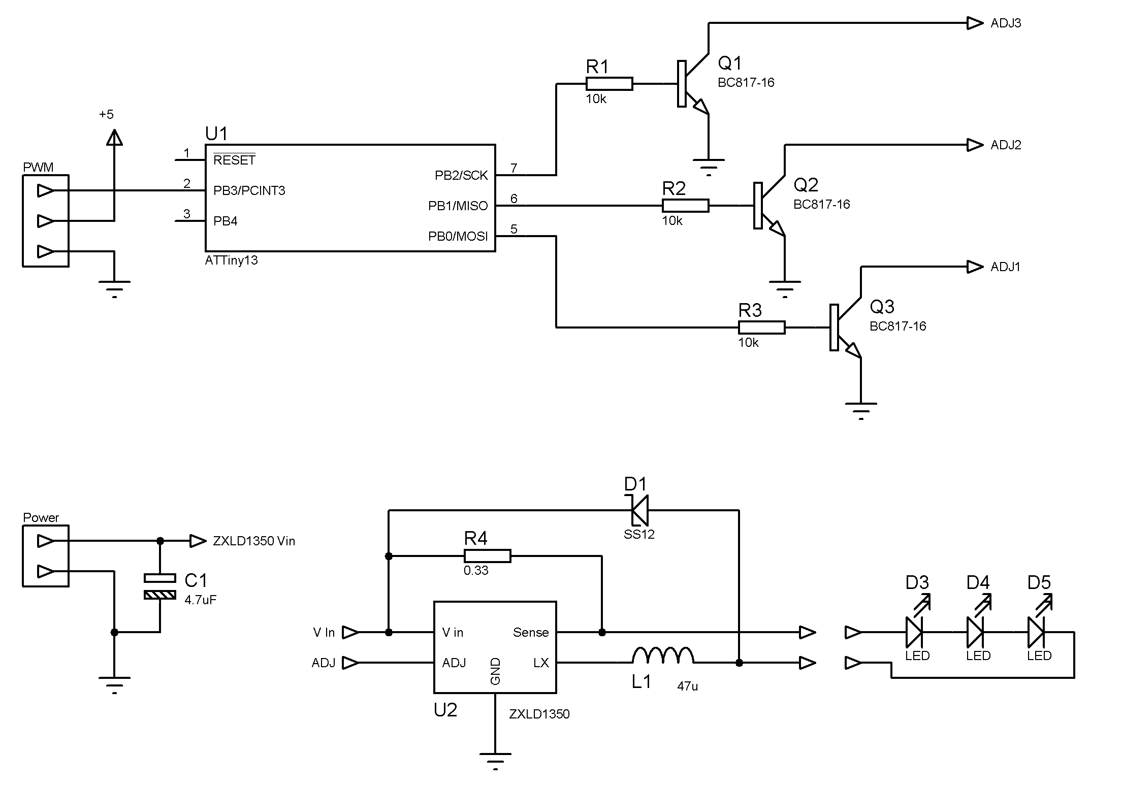
Scheme. Each channel is built according to a datasheet scheme. There are 4 such channels on the board (I drew only one). I drew 3 LEDs, but, as I said, you can put any number of LEDs on each channel. You can even put the LEDs of different colors (they drop a different voltage), the main thing that they were designed for the same current. The driver will select such a voltage, so that the current through the diodes does not exceed 350mA.
The ADJ input of three of the channels is connected to the controller output via a transistor. The ZXLD1350 driver has a special mechanism with which you can turn on and off the LED from the controller. Moreover, you can smoothly adjust the brightness by changing the voltage at the input or using PWM. That's just the operating voltage of the input from 0.3V to 2.5V, and from the controller gives 5V. Fortunately datasheet recommends the solution in the form of a transistor. It is only necessary to take into account that this transistor inverts the logical state - the zero on the foot of the controller will turn on the LED, and the unit will turn off. However, this is not a problem to fix programmatically.
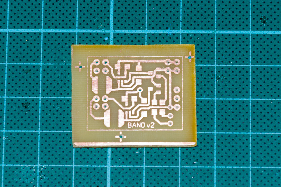
In order to save weight, I decided to try to make a two-way fee. I never became friends with LUT, but with photoresist everything came out the first time. I tried to play around with the solder mask, but I broke the technology and the mask lay down poorly (and some of which fell off altogether). Errors are taken into account for the future, and I will leave this attempt as it is. For the first time, it still rolls.
PCB layout Crosses on the edges are docking marks. I cut out the textolite a bit with a margin, then in the places of the crosses I drilled holes through which I then combined masks. Metalization of the holes did not, managed the jumpers. Well, the capacitor legs also work as a jumper between the sides.
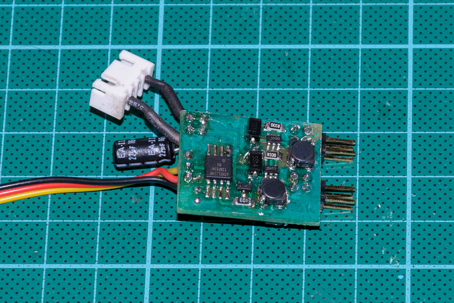
Ready product. Excess textolite cut by the frame. It turned out a scarf 27h22mm and weighing 4g. Well, another 2g on the wires and connectors turned out. The device is connected to the receiver via a standard three-pin JR connector. LED drivers take power from the battery balancing connector.
To whom 1W can not look at the ZXLD1360 chip a little. It is designed to supply 3W of LEDs (current 750mA). The wiring and pinout are the same, so that the wiring board is suitable. Only the nominal values of some parts need to change, smoke datasheet.
For those who have not pumped more in the etching of double-sided boards, I also post several options for one-way - for 2, 3 and 4 channels.
LEDs bought from the Chinese on ebee . I bought specially without a radiator, which does not fit everywhere. As the radiator used pieces of aluminum strip. The LED can be fixed with a special thermally conductive tape or glue. This is how it looks in the test version (here the radiator is small, it is heated)
And so on the previous model.
Firmware
Now you need to breathe life into this piece of iron. Since the source code of the firmware from the VETERAN SCREEN was not found in the internet, I had to do everything myself. No, I, of course, disassembled its firmware to see what was inside, but it was much more useful to just read the specification for ATTiny13.
Despite the fact that the microcontroller only 1Kb flash, I decided to write in C. It is more convenient and clearer. Arduino sketches, of course, they will be easier in some way, but everything that I have in mind will not fit into the controller's memory. Therefore I had to go down to a lower level and program the registers directly. To my surprise, the compiler (gcc 3.4.2 from Atmel Studio 6) generated pretty good code. There were, however, a couple of places where the compiler acted suboptimally, but these places were corrected.
The architectural problem of the firmware is that I needed to do several conceptually different actions at the same time - then blink, do not blink,
I will give a classic example. What if we need to blink one LED? Well, then our program will look something like this:
while(1) { led1(on); delay(500); led1(off); delay(500); } But what if we need to blink two LEDs, and even with different frequencies? Well, you can, of course, pervert and write something like this:
while(1) { led1(on); delay(300); led2(on); delay(200); led1(off); delay(500); led2(off); delay(200); } But most likely it will be very difficult to choose the timings and the sequence of on-off. If it works, of course (which I doubt). And if you need three blinking diodes? And four?
The correct solution is to use timers. But there is a problem: the timer in the microcontroller is only 1, and that eight-bit one.
In fact, where there is one timer, you can make arbitrarily many software timers. It looks like this: the hardware timer ticks with great frequency. For each timer triggering, the handler checks whether the specified time for the program timer has passed. If it does, call the handler.
Let's see how it will look like in code.
// Pointer to a timer handler typedef void (*eventHandler)(); // Software timers list typedef struct timer_t { uint16_t timeout; eventHandler handler; } timer_t; #define TIMERS_LIST_SIZE 5 timer_t timersList[TIMERS_LIST_SIZE]; A program timer is a counter how many times the main (iron) timer should scroll before calling the handler. A pointer to the handler is attached. For my tasks, three such entries are quite enough, but just in case I made a list of programmed timers with a size of 5 items.
I will describe the issue of setting the microcontroller timer a bit later. And now about the implementation of software timers. The initialization function looks simple - reset the list of timers.
void setupEventQueue() { // Clear timers list memset(timersList, 0, sizeof(timersList)); } In order to add a program timer, we simply look for an empty slot and enter timeout values in it plus a pointer to the handler. Error checking is absent in order to save space in the controller.
void addTimer(eventHandler handler, uint16_t timeout) { // Search through the timers list to find empty slot for(timer_t * timer = timersList; timer < timersList + TIMERS_LIST_SIZE; timer++) { if(timer->handler != NULL) continue; // Add the timer to the list timer->handler = handler; timer->timeout = timeout; break; } } The main loop is as follows.
void runEventLoop() { runTimer(); // Set up sleep mode set_sleep_mode(SLEEP_MODE_IDLE); while(1) // Main event loop { wdt_reset(); // Sleep until the timer event occurs sleep_enable(); sleep_cpu(); sleep_disable(); //Iterate over timers for(timer_t * timer = timersList; timer < timersList + TIMERS_LIST_SIZE; timer++) { // Skip inactive timers if(timer->handler == NULL) continue; if(timer->timeout) // Decrement timeout value { timer->timeout--; } else // If it is already zero - execute handler { timer->handler(); timer->handler = NULL; } } } } First, we start the timer (more on this below, everything is not so trivial there). Instead of active waiting, I use sleep. At the beginning of each cycle, the processor goes into Idle mode. This means that the CPU will fall asleep, but all the timers (ok, all, he alone!) Will continue to work. When the timer counts to the end and resets to zero, an interrupt occurs that wakes up the processor and the program goes on. Just what we need.
Yes, in the LED blinker a lot of electricity can not be saved, but in the future the same frame can be used in other applications where falling asleep to the processor can be very useful.
If we woke up it means that it's time to go through the list of programmed timers. In each record we reduce the value of the counter. If you have already reached zero, then we call the handler, after which we delete the timer from the list (by writing NULL to the pointer to the handler).
Since everything happens in one thread, no mutexes and locks are required.
To blink the LED with a fixed frequency, the handler will look like this: invert the state of the LED, ask the system to call the same handler again after a while.
#define LED_A_PIN PORTB0 void toggleLedATask() { PORTB ^= (1 << LED_A_PIN); addTimer(toggleLedATask, TIMEOUT_MS(300)); } To make it all work, you need the handler to somehow volunteer for the first time. To do this, before starting the main loop, just put a message in the queue that it’s time to call the handler with a delay of 0 ms (that is, immediately at the first opportunity).
int main(void) { // Set up ports PORTB = 1 << LED_A_PIN; // LEDs switched off DDRB = 1 << LED_A_PIN; // output mode for LED pins setupEventQueue(); addTimer(toggleLedATask, TIMEOUT_MS(0)); sei(); runEventLoop(); } Initially, the pin is adjusted to the output. I remind you that the LEDs are connected through an inverter. So in order to turn off the default LED, you need to write a unit to the port.
Well, blinking back and forth is not interesting. Is there anything more abruptly? For example, blink once, then after a pause, blink twice, then thrice, repeat, shake, not stir. Well, this is also not difficult.
#define LED_B_PIN PORTB1 uint8_t delayIndex = 0; const uint16_t delays[] = { TIMEOUT_MS(100), //on TIMEOUT_MS(700), //off TIMEOUT_MS(100), //on TIMEOUT_MS(200), //off TIMEOUT_MS(100), //on TIMEOUT_MS(700), //off TIMEOUT_MS(100), //on TIMEOUT_MS(200), //off TIMEOUT_MS(100), //on TIMEOUT_MS(200), //off TIMEOUT_MS(100), //on TIMEOUT_MS(1200), //off }; void complexLedTask() { PORTB ^= (1 << LED_B_PIN); uint16_t delay = delays[delayIndex]; delayIndex ++; if(delayIndex >= sizeof(delays)/sizeof(uint16_t)) //dim(delays) delayIndex = 0; addTimer(complexLedTask, delay); } Just make a table with timings. The handler each time changes the state of the LED and waits for the time specified in the table.
In order to blink several LEDs simultaneously and independently, simply add several similar handlers, not forgetting to configure the port and add handlers to the list.
int main(void) { // Set up ports PORTB = 1 << LED_A_PIN | 1 << LED_B_PIN | 1 << LED_C_PIN; // LEDs switched off DDRB = 1 << LED_A_PIN | 1 << LED_B_PIN | 1 << LED_C_PIN; // output mode for LED pins setupEventQueue(); addTimer(toggleLedATask, TIMEOUT_MS(0)); addTimer(complexLedTask, TIMEOUT_MS(0)); addTimer(blinkLedCTask, TIMEOUT_MS(0)); sei(); runEventLoop(); } Of course, you still need to get used to this style of programming, but in general the approach works well. Remember, if we are writing a multi-threaded application for a large computer, usually each thread has an eternal loop and maybe some kind of sleep or wait. Consider that the above handlers are the body of that same eternal loop, and the addTimer () call is the same sleep.
How often should the main timer tick? If it rarely ticks, it will reduce the accuracy of the measured time intervals. On the other hand, for each timer cycle you will need to do a certain number of useful actions. And these actions need to have time to finish before the next timer cycle. So the timer should tick and not very often as well.
Those. not often and not rarely. But how exactly? Ok, for the previous task the range of possible values is quite large. But you also need to remember the task “listen to PWM input”. More specifically, there are pulses with a duration of 800-2200 μs and we will have to measure this length. For our task to turn on / off the LED on the command from the remote, we will read as follows: if the pulse is shorter than 1500µs, the LED is off, if it is longer, it is on.
Translated into the language of microcontrollers and timers, we will count how many timer ticks fit in the measured time interval. The problem occurs when the pulse duration is approximately equal to the threshold. Then false alarms are possible and the LED will blink as the pulse length changes. To reduce the chance of blinking, we need to more accurately measure the length of the pulse. I think the resolution of the timer should be in the region of 1-2 μs - such a resolution will ensure sufficient accuracy of measurements.
If we are talking about specific numbers you need to understand the frequency of the microcontroller. The controller can be clocked from the internal and from the external generator. The external generator is more accurate, but these are additional details and weight. Yes, and we do not need accuracy especially. Of the internal oscillators, 128 kHz, 4.8 MHz and 9.6 MHz are available. 128kHz is not enough, we will choose between the other two options.
The timer, in turn, can have the same frequency as the microcontroller, and it can activate the frequency divider by 8, 64, 256 or 1024. The timer itself counts from 0 to 255 and then resets to 0. If the divider does not use one tick the timer corresponds to one processor tick, which in most cases corresponds to a single command. We were going to do useful work every full timer cycle. But if we need to do this work every 256 teams, then we simply will not have time to do this work (or there should be very very little of it).
So, you need to choose between the frequency 4.8 MHz and 9.6 MHz, and the dividers 8, 64 and 256. As for me, the 4.8 MHz option with the divider 8 is quite successful. The timer will tick at 4.8 MHz / 8 = 600 kHz. This means that one tick will take 1.666 μs. Just fit in the desired 1-2mks. The full cycle of the timer will take 1,666 * 256 = 426.66 μs. As a program timer, we use a 16-bit variable, which means we are able to measure time intervals of 65536 * 426.66 μs = 27.96 s (with the accuracy of the same 426.66 μs)
Timer start code:
void runTimer() { // Reset timer counter TCNT0 = 0; // Run timer at 4.8MHz/8 = 600 kHz // This gives 1.667 uSec timer tick, 426.667 uSec timer interval // Almost 28 seconds with additional 16bit SW timer value TCCR0A = 0; // Normal mode TCCR0B = 0 << CS02 | 1 << CS01 | 0 << CS00; // run timer with prescailer f/8 } In the code above, I used the mysterious TIMEOUT_MS macro. It's time to decipher it.
#define TIMEOUT_MS(t) ((uint32_t)t * 600 / 256) //4.8MHz / (8 prescailer * 256 full timer cycle * 1000 since we are counting in ms) This macro determines the number of cycles at 426.6 µs required to measure a specified number of milliseconds. Unfortunately, when I banged the full formula (the one in the commentary), then the compiler started generating terrible problems that I could not cope with. I had to recount the formula to the incomprehensible now 600/256.
But back to hearing PWM input. To be a little clearer, I will tell you again how everything works, but in other words. The main 8-bit timer ticks from 0 to 255. Each full cycle of the timer, we process a list of software timers and start handlers, if needed. In addition, the value of the 8-bit timer itself is used in the measurement of the pulse length at the input. This is done very simply: if the impulse has begun, we remember the value of the timer. While the pulse goes the timer keeps ticking. By the time the impulse ends, the timer is docked to some new value. Accordingly, by the difference of values, we can calculate the pulse length simply by multiplying by the time of one tick (1.666 μs)
Stop! The timer is 8bit and that means that only pulses up to 256 * 1.66 = 426.66µs can be measured in this way, while incoming pulses up to 2200µs long. No problem! You can artificially extend the timer counter by adding as many high bytes as needed. The usual binary mathematics operates - when the low byte overflows we increment the high bytes.
// Additional high byte for 8bit timer value volatile uint8_t tcnth; void runTimer() { // Reset timer counters tcnth = 0; TCNT0 = 0; // Run timer at 4.8MHz/8 = 600 kHz // This gives 1.667 uSec timer tick, 426.667 uSec timer interval // Almost 28 seconds with additional 16bit SW timer value TCCR0A = 0; // Normal mode TCCR0B = 0 << CS02 | 1 << CS01 | 0 << CS00; // run timer with prescailer f/8 TIMSK0 = 1 << TOIE0; } Almost all the same. Only the variable tcnth was added - the “high” byte in addition to the low byte inside the timer. The last line is also important - it includes the timer overflow interrupt. This interrupt will increment the high byte:
ISR(TIM0_OVF_vect) { // Increment high byte of the HW counter tcnth++; } Notice that the tcnth variable is declared volatile. Without this keyword, the compiler in another part of the program might think that the variable does not change and optimize too much. He does not know that the variable changes in the interrupt (in fact in another thread).
In order to catch the beginning and end of the pulse, you can use a specially designed for this pin change interrupt - an interrupt that will be triggered just when the value changes at the input. So you do not need to constantly poll the input - the microcontroller will do all the work. We just have to write an interrupt handler.
uint16_t pwmPulseStartTime; #define PWM_THRESHOLD 900 // number of pulses in 1500 uS at 4.8MHz with /8 prescailer = 1500 * 4.8 / 8 = 900 // Pin Change interrupt ISR(PCINT0_vect) { /* // Get the current time stamp uint16_t curTime = (tcnth << 8) + TCNT0; Unfortunately gcc generates plenty of code when constructing 16 bit value from 2 bytes. Let's do it ourselves */ union { struct { uint8_t l; uint8_t h; }; uint16_t val; } curTime; // Get the current time stamp curTime.h = tcnth; curTime.l = TCNT0; // It may happen that Pin Change Interrupt occurs at the same time as timer overflow // Since timer overflow interrupt has lower priority let's do its work here (increment tcnth) if(TIFR0 & (1 << TOV0)) { curTime.h = tcnth+1; curTime.l = TCNT0; } if(PINB & (1 << PWM_INPUT_PIN)) // On raising edge just capture current timer value { pwmPulseStartTime = curTime.val; } else // On failing edge calculate pulse length and turn on/off LED depending on time { uint16_t pulseLen = curTime.val - pwmPulseStartTime; if(pulseLen >= PWM_THRESHOLD) PORTB |= (1 << LED_C_PIN); else PORTB &= ~(1 << LED_C_PIN); } } The first part of the handler is devoted to pulling out the value of the timer counter (extended by an additional external byte). Unfortunately, subtracting the value in the forehead did not work - from time to time the LED blinked spontaneously. This happened because 2 interrupts occurred approximately simultaneously. And since the timer interrupt has a lower priority, the handler was sometimes not called when it followed. As a result, the high byte was not increased, which means the total value turned out to be 256 units less. This is significant.
The solution is quite simple - to check whether the overflow of the timer occurred and, if it does, do the same job as the handler for this overflow - to do +1 for the high byte.
At this point, I came across a non-optimal code generated by a vile. The code (tcnth << 8) + TCNT0 compiled like this, with shifts and additions. And this is despite the included optimization (-O1). I, in this place, need only 2 bytes to interpret as a 16-bit number. I had to make a fuss with unions.
The second part of the handler does the actual useful work. If we caught the beginning of the impulse - just remember the time stamp in the variable pwmPulseStartTime. If we caught the end of the pulse, we consider the difference in time marks and turn on / off the LED depending on the value. Threshold is 1500ms, or 900 timer ticks of 1.66µs each.
What is missing here is the initialization of the pin change interrupt itself:
#define PWM_INPUT_PIN PCINT3 void setupPWMInput() { // Initialize the timestamp value pwmPulseStartTime = 0; // Set up pin configuration PORTB |= 1 << PWM_INPUT_PIN; // pull-up for PCINT3 DDRB &= ~(1 << PWM_INPUT_PIN); // output mode for LED pins, input mode for PCINT3 pin // Use PCINT3 pin as input PCMSK = 1 << PWM_INPUT_PIN; // Enable Pin Change interrupt GIMSK |= 1 << PCIE; } Almost everything is ready. Of the requirements are not implemented only smooth blinking. In fact, the controller can only turn on and off the LED. There are no intermediate values. But if you quickly quickly turn on and off with a given duty cycle (the ratio of time when the LED lights up to the time when it is off), then the person thinks that the LED still shines smoothly, only with lower brightness. Well, if you gradually change the duty cycle, it will seem that the brightness of the LED changes smoothly.
You can write code that will turn the LED on and off. The benefit of timers can now be done as you want. But why, if PWM generation is already built into the controller? Moreover, it is possible to independently control as many as two generation channels - on the legs of OC0A and OC0B (they are PB0 and PB1).
It works like this. A single timer rotates as usual with a given speed. At the beginning of the cycle, a unit is set at the leg, and when a certain specific value is reached (specified by registers OCR0A and OCR0B), a zero is set at the leg. Then the cycle repeats. The larger the register value, the greater the duty cycle and the brighter the diode. This is called Non-Inverting mode. Since the LEDs are connected via an inverter, Inverting mode is more suitable for us - we turn on by value in the register, turn off when the timer reaches the end and resets.
// Current PWM value volatile uint8_t pwmAValue = 1; volatile uint8_t pwmBValue = 1; void runTimer() { // Reset counter counters tcnth = 0; TCNT0 = 0; OCR0A = pwmAValue; OCR0B = pwmBValue; // Run timer at 4.8MHz/8 = 600 kHz // This gives 1.667 uSec timer tick, 426.667 uSec timer interval // Almost 28 seconds with additional 16bit SW timer value //TCCR0A = 1 << COM0A1 | 1 << COM0A0 | 1 << COM0B1 | 1 << COM0B0 | 1 << WGM01 | 1 << WGM00; // Fast PWM on OC0A and OC0B pins, inverting mode TCCR0A = 1 << COM0A1 | 1 << COM0A0 | 1 << WGM01 | 1 << WGM00; // Fast PWM on OC0A pin, inverting mode TCCR0B = 0 << CS02 | 1 << CS01 | 0 << CS00; // run timer with prescailer f/8 TIMSK0 = 1 << TOIE0; } I had to slightly adjust the timer initialization. Bits WGM00 and WGM01 include Fast-PWM generation mode. Bits COM0A0, COM0A1, COM0B0, and COM0B1 include Inverting mode in channels A and B. More precisely, the entered line includes in both, the unclaimed line only for OC0A.
Since the values in the variables pwmAValue change from time to time, you need to somehow let you know about this timer. This is best done in the overflow handler.
ISR(TIM0_OVF_vect) { // Update the PWM values OCR0A = pwmAValue; OCR0B = pwmBValue; // Increment high byte of the HW counter tcnth++; } You can, of course, directly and directly push the values into the OCR0A and OCR0B registers, but this is not recommended by the datasheet. This can lead to a “skipping” when the value of a pin changes sooner or later than it should. Visually, this would manifest itself in an undesirable sharp and short-term change in brightness.
The brightness itself can be changed in the already familiar program timers. For example:
uint8_t directionA = 0; void pwmLedATask() { if(directionA) // Incrementing { pwmAValue += 2; if(pwmAValue == 255) directionA = 0; } else //decrementing { pwmAValue -= 2; if(pwmAValue == 1) directionA = 1; } addTimer(pwmLedATask, TIMEOUT_MS(2)); } Just gradually increase or decrease the value of the variable pwmAValue, which will then be entered into the corresponding register. Although to emulate a real flashing light, you will have to come up with something more beautiful. For example:
typedef struct complexPWM { uint8_t step; uint8_t maxValue; uint16_t delay; } complexPWM; complexPWM pwmItems[] = { {0, 1, TIMEOUT_MS(1000)}, {2, 127, TIMEOUT_MS(2)}, {-2, 33, TIMEOUT_MS(2)}, {2, 255, TIMEOUT_MS(2)}, {-2, 1, TIMEOUT_MS(2)} }; uint8_t pwmTableIndex = 0; void complexPWMTask() { complexPWM * curItem = pwmItems + pwmTableIndex; pwmAValue += curItem->step; if(curItem->maxValue == pwmAValue) pwmTableIndex++; if(pwmTableIndex == sizeof(pwmItems)/sizeof(complexPWM)) //dim(pwmItems) pwmTableIndex = 0; addTimer(complexPWMTask, curItem->delay); } I'm not sure that this looks like a flashing beacon, but in this piece of code a pre-flash is made to brightness 127, then we reduce the brightness to 33 and make a full flash (to 255).
On this, probably, on the firmware and that's it. With all the giblets and morgulkas everything is 500-600 bytes - there is even a reserve. It remains to highlight one important point - Fuse bits. They are equal to hfuse = 0xff, lfuse = 0x79. For decoding, I will ask for a datasheet. In a nutshell, a couple of bits in these bytes make the controller operate at 4.8 MHz. The remaining bits are left in the default state.
How it looks in reality can be estimated by the video in the header of the article.
Conclusion
In this article, I described my version of the controller for different aircraft-made light bulbs - BANO, landing lights and strobes. All that remains is a bit of crafting the firmware and your copy models will look like real ones.
Moreover, a similar blinker can be put on the car. And you can, for example, highlight the advertising sign. All in your hands.
But not single planes. In addition to the blinking light bulbs, I covered in the article a few other points related to the programming of weak controllers:
- How to emulate multiple timers on one timer
- How to choose timer parameters
- How to set the timer in PWM generation mode
- How to listen to PWM input and do useful work based on read values
If we abstract away from the task of blinking with LEDs, then we get a pretty good frame for “multitasking” (“multithreaded”?) Applications on the microcontroller. Of course, this is not RTOS, but it already eliminates a whole heap of routine operations. In the firmware, I made this framework into a separate module EventQueue.c / .h. Use nasdorove.
It's nice that we got 3 completely independent tasks (counting long periods of time, measuring the duration of the pulses at the input and generating PWM at the output) managed to be hung up on a single 8-bit timer. Well, on the added software timers, you can still do a lot of useful things.
The code, however, turned out not very structured. Different tasks are solved in the same functions, with each task being spread in several places. But this is a fee for a compact size. As well as the lack of buttons and other means of entering information. But, I repeat, I didn’t get soldered once by soldering the programmer wires directly to the controller, configuring the necessary blinking option in the code and pouring it all in the form of firmware.
The article is not a reference book - all the same, you will have to go to the datasheet for clarification of certain bits and registers. This is just a kind of example, how can you use some meager hardware by using the means of a junior controller in the AVR line?
Initially, I did not plan to attach to the article the final compiled hex file. The fact is that all models are different. Somewhere you need another number of channels, somewhere you need to blink differently, you may need to add a couple of inputs, or do something else. Instead, I would suggest that you try changing the firmware yourself so that you fully fit your idea. Everything is simple there!
However, not all model airplanes are friends with the compiler. So I nevertheless compiled a certain average variant: one channel blinks once every 2 seconds (strobe), the PWM channel flashes a little more often with double flashes, the third channel is turned on by a command from the console, the fourth, as before, always shines. This firmware will be a certain starting point for the subsequent dopilivaniya. The examples presented in the article, I also left in the code, only calls zakommentaril.
Successes!
Sources of firmware and wiring boards .
Source: https://habr.com/ru/post/228083/
All Articles