Astro tracker for two evenings
After reading the article about amateur astronomy, I got excited about the idea of shooting stars with a conventional camera without a telescope. The article suggested the idea of astro trackers - a device for compensating the rotation of the starry sky for long exposures.
Googling, I found that they can be easily bought. But the price bite. For example, the cheapest Vixin Ploarie Star Tracker costs from $ 400 + shipping. Yes, and its load caused doubts. In the future, I was planning to move from a wide-angle lens to 70-200 / 2.8, which, together with the camera, weighs under one and a half kg.
')
In the process of searching, it turned out that people are doing the so-called Barn Door trackers: one , two and others . Simply put - the door of the barn. The principle of operation is simple - two boards connected by a canopy. One of them turns at the same speed as the earth around its axis. The axis of the canopy is directed to the Polar Star. The bottom board is placed on a tripod, and a tripod head with a camera is placed on the movable half.
Under the cut a lot of pictures.
I was excited to make such a tracker myself. For without it, you can only shoot star tracks like this.

According to estimates, almost everything was on hand. I decided to take this tracker as a basis. There is also a description in the description of the methodology for calculating the basic parameters.
10mm MDF was chosen as material for the construction. had the experience of his laser cutting in the workshop. Material cheap, comfortable. In terms of reliability, it's too early to say. Let's look at trial operation.
First, in the CAD program, I drew a model of what needed to be done. For this we had to calculate the radius and rotation speed of the stud. According to my estimates, the radius turned out to be 182.85mm for an M5 stud with a pitch of 0.8mm and a nut rotation speed of 1 rpm. The stud was chosen by the M5 as a compromise between strength and thread pitch.

Since subsequently I wanted to shoot at 70-200 / 2.8, then I had to calculate how many engine steps to do per minute so that there was no blurring within one pixel. After all the estimates, I made a tenfold margin so that the errors in the manufacture of the structure would not drastically worsen the situation.
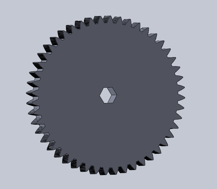
To rotate the nut on the stud in the original design used gears. But to find the gear for adequate money did not work. Were only on e-bay and even then for $ 10 + with delivery per month. Therefore, the gear decided to also cut with a laser of MDF or acrylic.

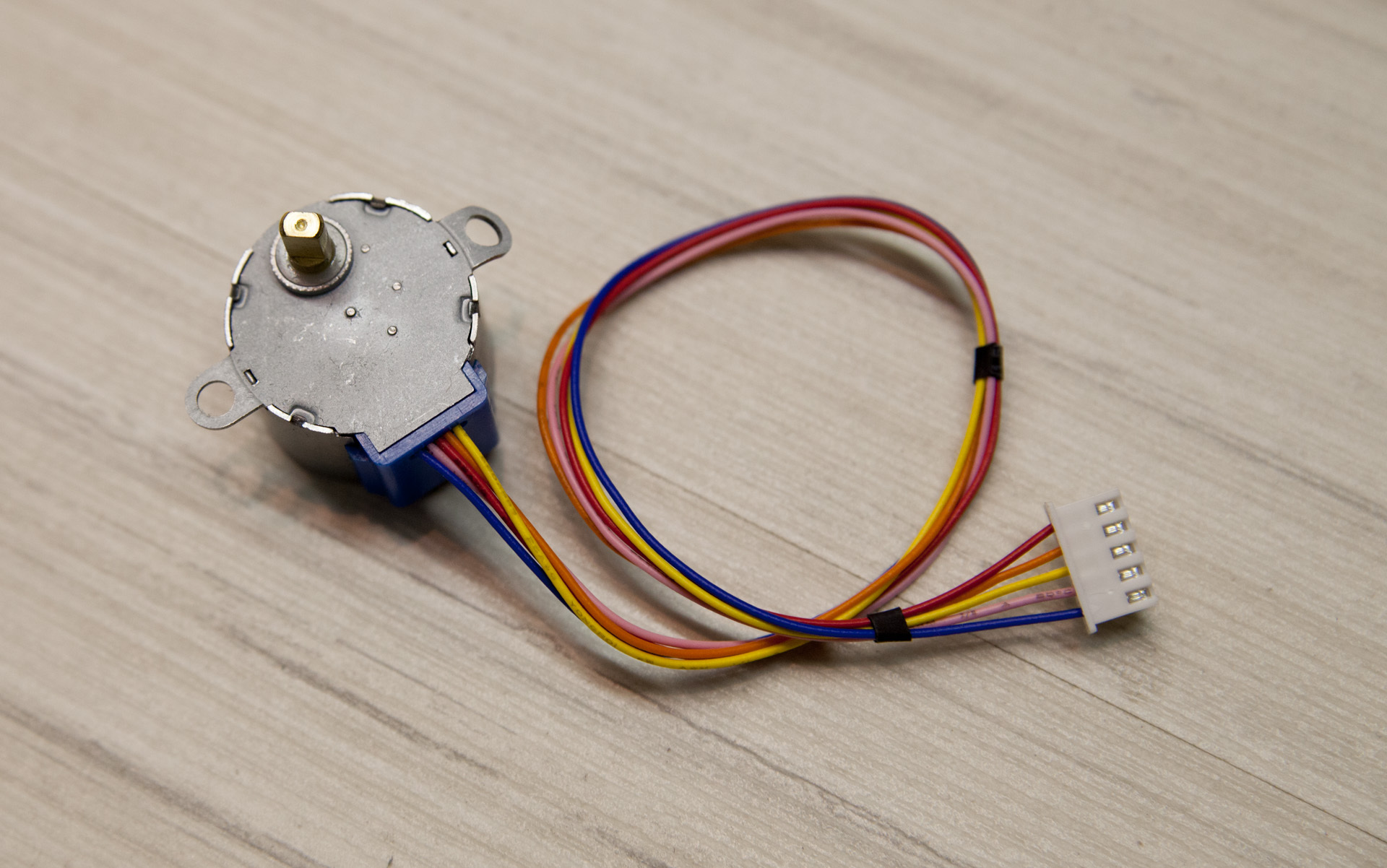
The engine used stepper Chinese 28BYJ-48. I had several pieces of them for a long time, everyone wanted to play. They cost less than $ 2 on ebay with delivery. It eats from 5-12 volts. Makes one revolution of the shaft in 64 steps. It also has a gearbox with a coefficient close to 63.68395: 1. Thus, the external axis rotates in 2037 steps in 4-step mode or 4075-steps in 8-step mode. The torque is not great, but for this task it is more than enough. On the Internet, they write that it was possible to get about 15 rev / min from him but with an increase in power to 12V. I decided that 4 rpm was enough for me and made gears with a ratio of 4: 1 for four turns of the engine, the nut on the stud would make one turn.

In the store I bought a carport with minimal backlash. Its envelope and became the width dostochek. In the same place I bought a hairpin. In another store scored mounting material. On fasteners, MDF with cutting, the loop took about 100 UAH. ($ 8.3). On ebay I ordered a small ball head, but so far I have put the usual one from the old tripod.
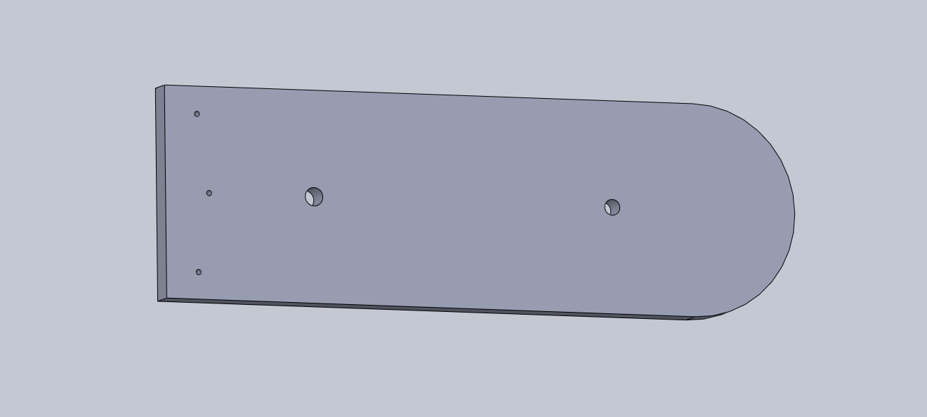
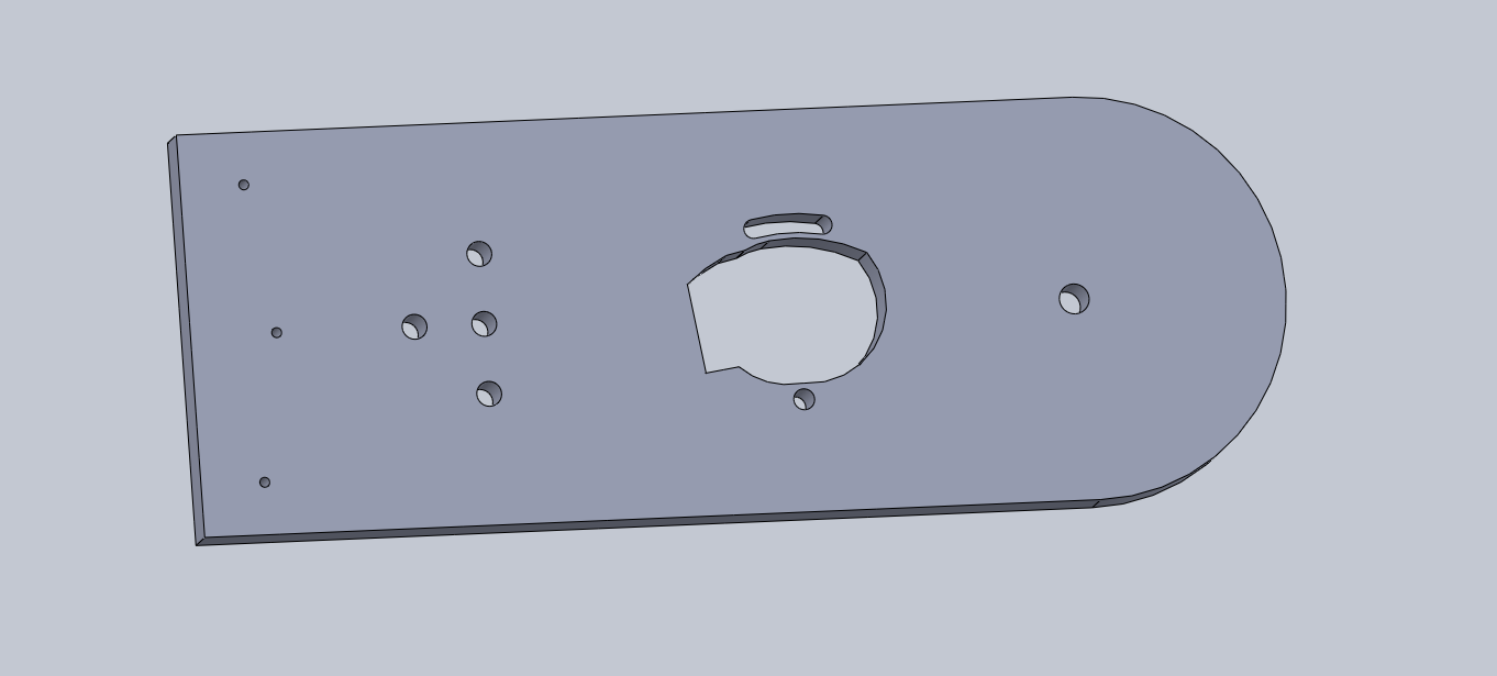
In the bottom half I made holes for attaching the Manfrotto 804RC2 photo head to the removable pad while I was away. Also made holes for the engine. I provided for adjusting the distance between the gears by rotating the motor around one of the mounting holes.
When I was satisfied with the drawing, I took it to the cutting and brought here such wonderful but strongly smelling as fumes items.
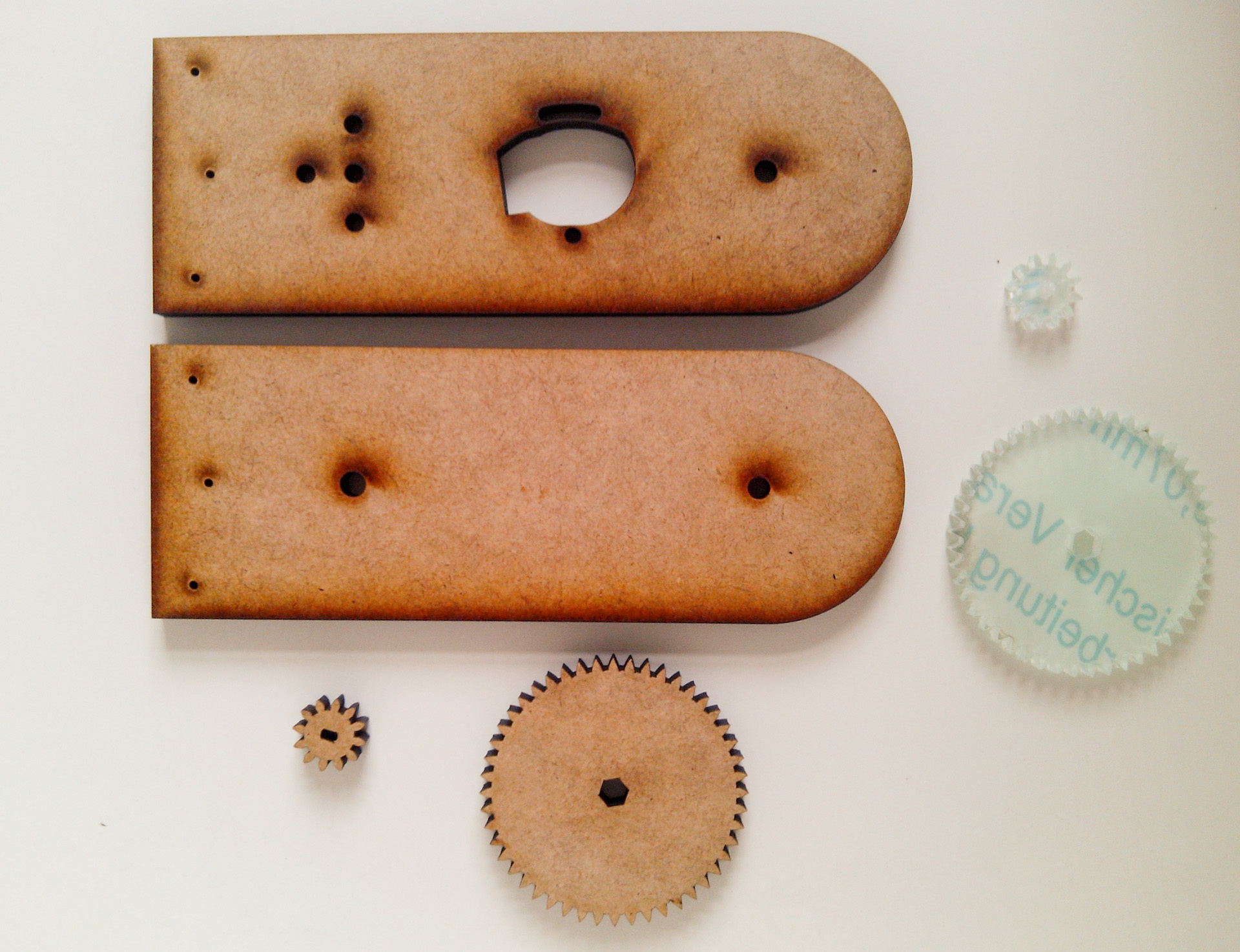
The gears were cut from both acrylic and MDF. With acrylic turned bad, the ends of the teeth floated. I had to process them with a file. Subjectively, the MDF move was softer. But let's look at combat conditions.

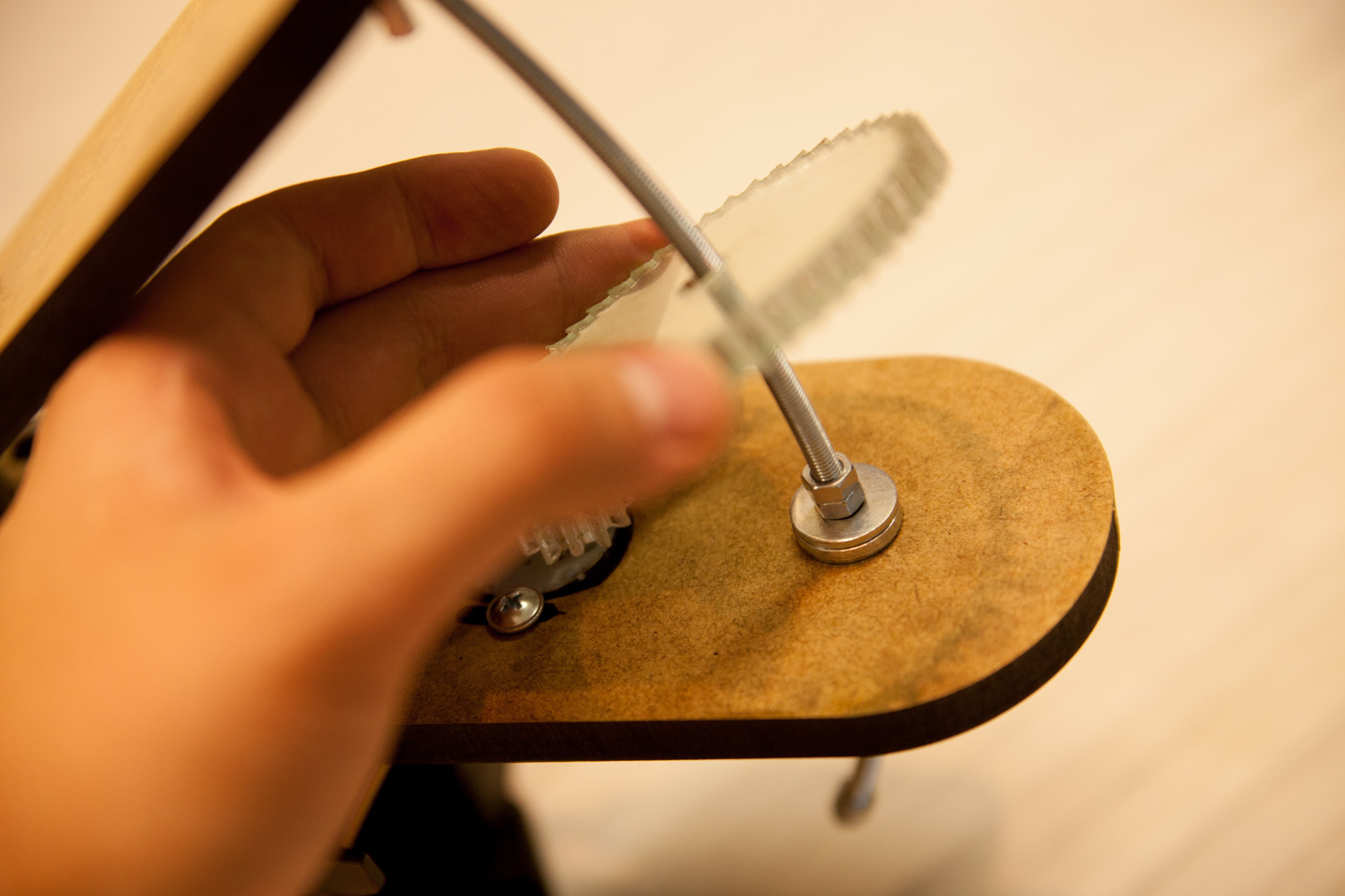
The fastening of the gear to the nut is very simple - a hole in the shape of a hexagon with a minimum tolerance. Acrylic - 8mm. Just fit 2 nuts M5.
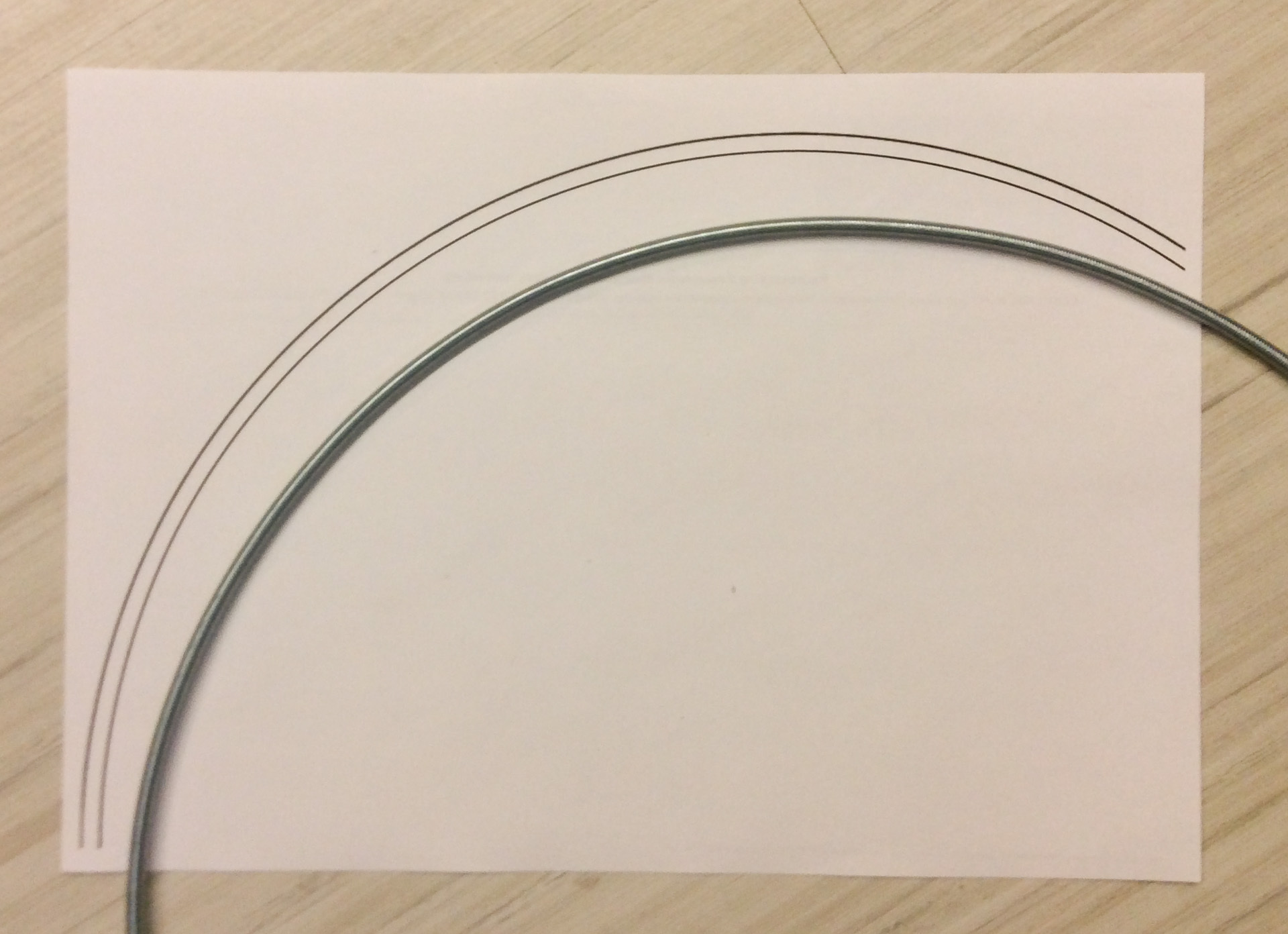
In order for the accuracy of reference to be higher, the pin must be bent by an arc. This is done like this: we print on the printer two concentric circles of the desired diameter so that their edges are the size of the stud. And slowly we bend it and constantly apply it to the template, check it. It is better to bend the entire pin at once (its length is 1 meter) - this is easier. Short - do not bend gently with your hands. In 10 minutes everything was ready.

Excess cropped Dremel. I left a segment of about 25 centimeters. This is enough for more than 5 hours of reference.
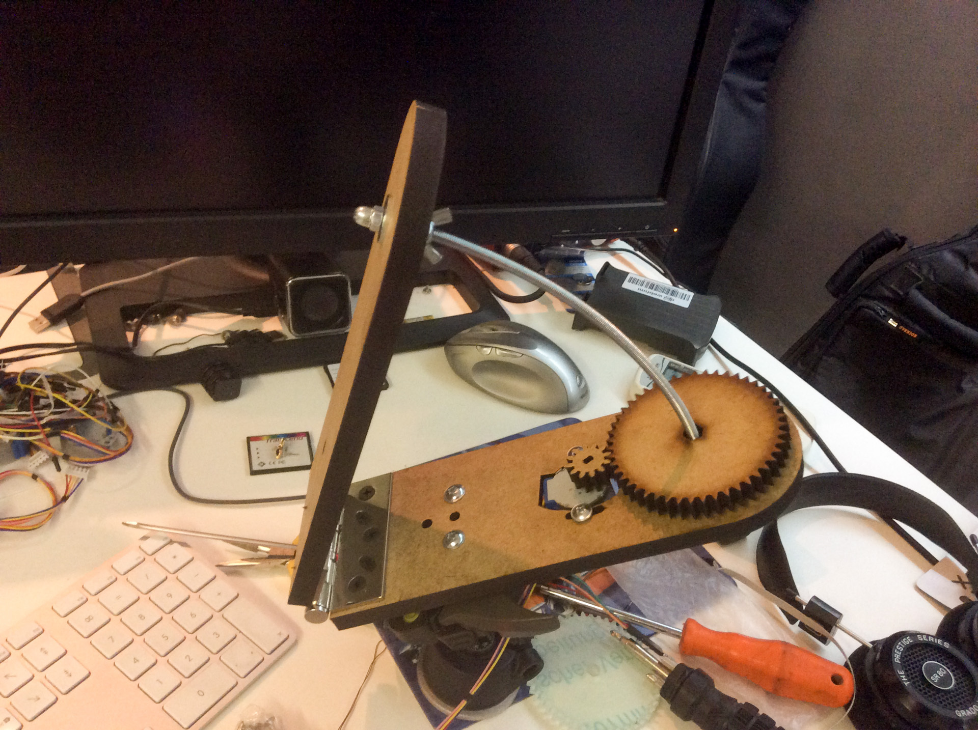
Putting it all together:
Check the rotation on a pre-written sketch for arduino.
I used the LCD Keypad Shield so that it would be convenient to select the rotation speed.
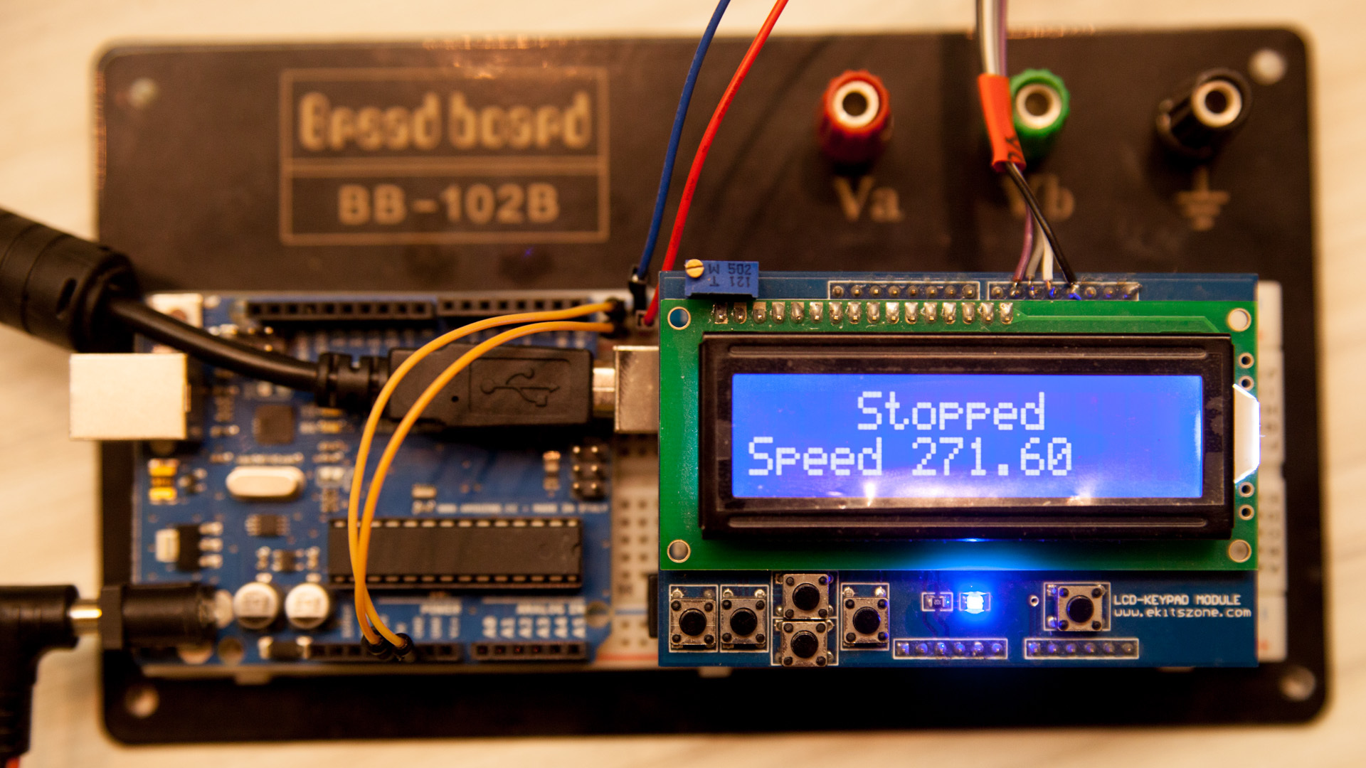
There is a Start / Stop button. There is an increment / decrement of 25 steps and a step of 0.1. Speed is measured in steps per second. Estimated speed should be 271.6 steps per second. But I can’t check it yet. it rains constantly.
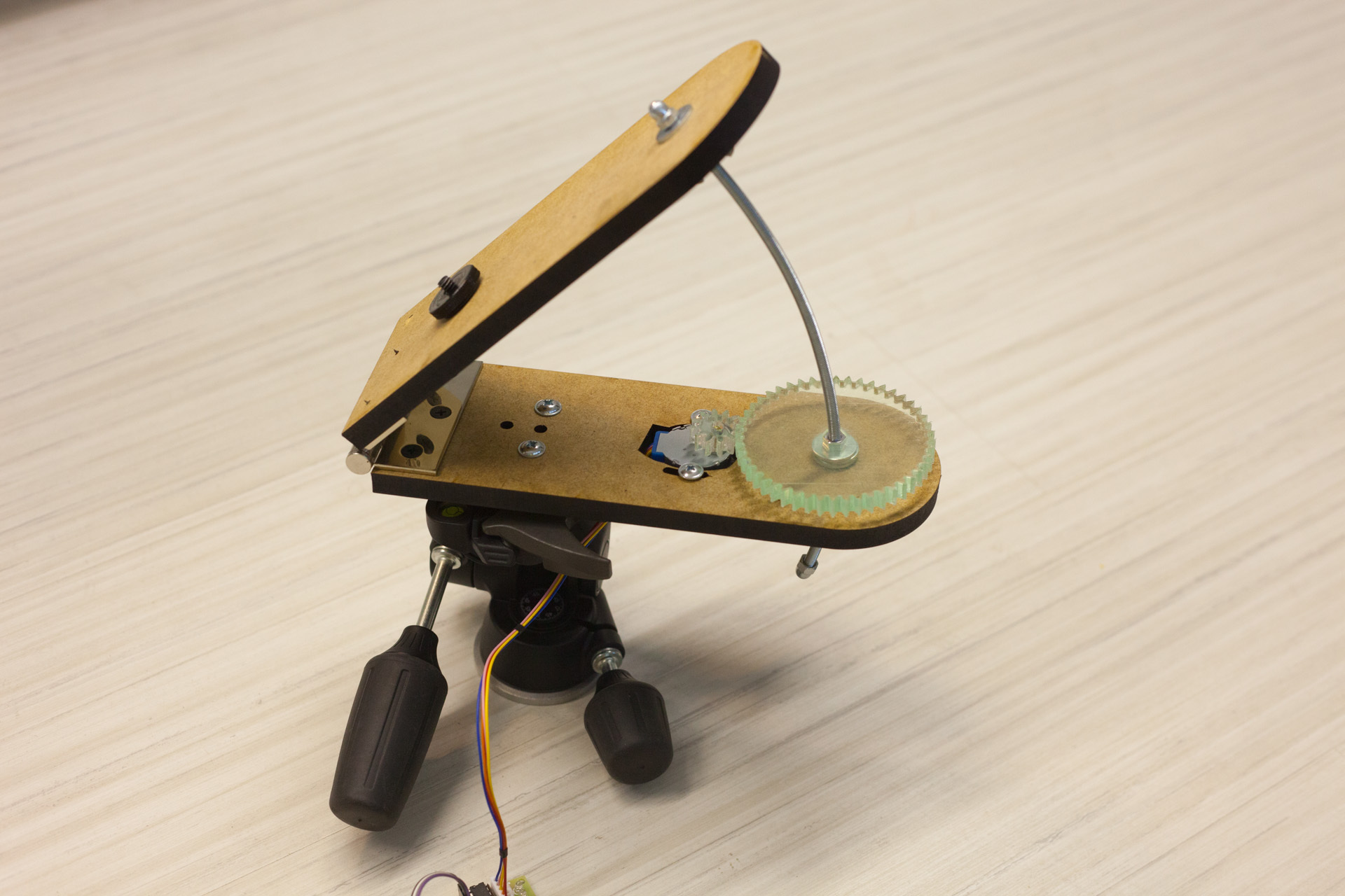
General view of the resulting structure
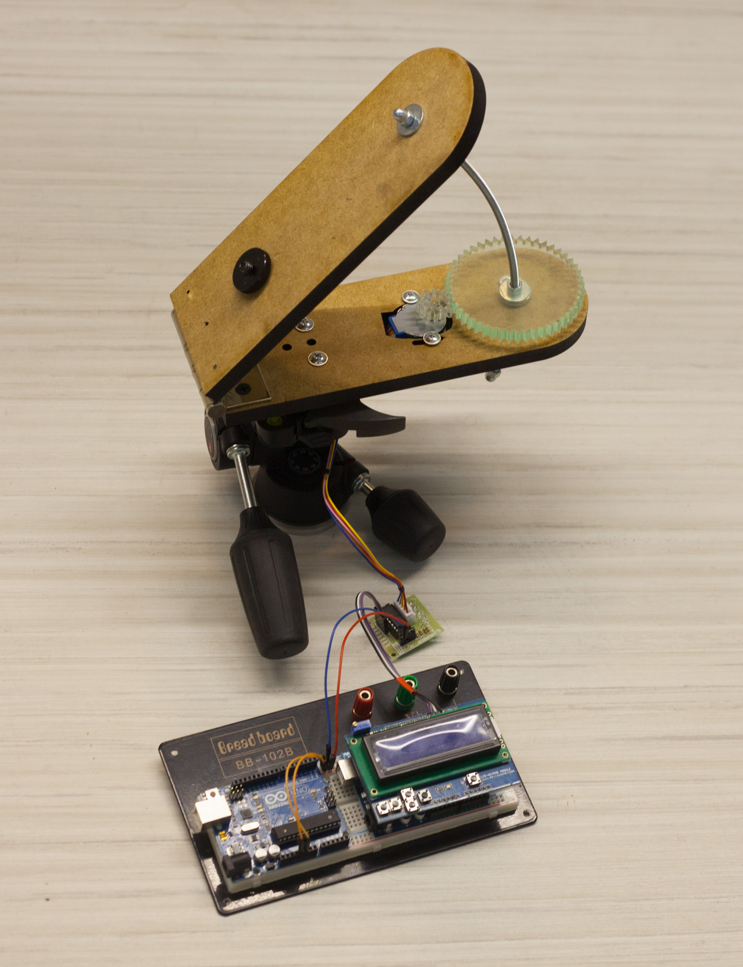
There are two arduins. Never mind. One is used as a power source for the engine.
Work process video
Now the weather is disgusting. It rains. As soon as the stars will be visible, I will start testing the mount in the field.
Googling, I found that they can be easily bought. But the price bite. For example, the cheapest Vixin Ploarie Star Tracker costs from $ 400 + shipping. Yes, and its load caused doubts. In the future, I was planning to move from a wide-angle lens to 70-200 / 2.8, which, together with the camera, weighs under one and a half kg.
')
In the process of searching, it turned out that people are doing the so-called Barn Door trackers: one , two and others . Simply put - the door of the barn. The principle of operation is simple - two boards connected by a canopy. One of them turns at the same speed as the earth around its axis. The axis of the canopy is directed to the Polar Star. The bottom board is placed on a tripod, and a tripod head with a camera is placed on the movable half.
Under the cut a lot of pictures.
I was excited to make such a tracker myself. For without it, you can only shoot star tracks like this.
According to estimates, almost everything was on hand. I decided to take this tracker as a basis. There is also a description in the description of the methodology for calculating the basic parameters.
10mm MDF was chosen as material for the construction. had the experience of his laser cutting in the workshop. Material cheap, comfortable. In terms of reliability, it's too early to say. Let's look at trial operation.
First, in the CAD program, I drew a model of what needed to be done. For this we had to calculate the radius and rotation speed of the stud. According to my estimates, the radius turned out to be 182.85mm for an M5 stud with a pitch of 0.8mm and a nut rotation speed of 1 rpm. The stud was chosen by the M5 as a compromise between strength and thread pitch.
Since subsequently I wanted to shoot at 70-200 / 2.8, then I had to calculate how many engine steps to do per minute so that there was no blurring within one pixel. After all the estimates, I made a tenfold margin so that the errors in the manufacture of the structure would not drastically worsen the situation.
To rotate the nut on the stud in the original design used gears. But to find the gear for adequate money did not work. Were only on e-bay and even then for $ 10 + with delivery per month. Therefore, the gear decided to also cut with a laser of MDF or acrylic.
The engine used stepper Chinese 28BYJ-48. I had several pieces of them for a long time, everyone wanted to play. They cost less than $ 2 on ebay with delivery. It eats from 5-12 volts. Makes one revolution of the shaft in 64 steps. It also has a gearbox with a coefficient close to 63.68395: 1. Thus, the external axis rotates in 2037 steps in 4-step mode or 4075-steps in 8-step mode. The torque is not great, but for this task it is more than enough. On the Internet, they write that it was possible to get about 15 rev / min from him but with an increase in power to 12V. I decided that 4 rpm was enough for me and made gears with a ratio of 4: 1 for four turns of the engine, the nut on the stud would make one turn.
In the store I bought a carport with minimal backlash. Its envelope and became the width dostochek. In the same place I bought a hairpin. In another store scored mounting material. On fasteners, MDF with cutting, the loop took about 100 UAH. ($ 8.3). On ebay I ordered a small ball head, but so far I have put the usual one from the old tripod.
In the bottom half I made holes for attaching the Manfrotto 804RC2 photo head to the removable pad while I was away. Also made holes for the engine. I provided for adjusting the distance between the gears by rotating the motor around one of the mounting holes.
When I was satisfied with the drawing, I took it to the cutting and brought here such wonderful but strongly smelling as fumes items.
The gears were cut from both acrylic and MDF. With acrylic turned bad, the ends of the teeth floated. I had to process them with a file. Subjectively, the MDF move was softer. But let's look at combat conditions.
The fastening of the gear to the nut is very simple - a hole in the shape of a hexagon with a minimum tolerance. Acrylic - 8mm. Just fit 2 nuts M5.
In order for the accuracy of reference to be higher, the pin must be bent by an arc. This is done like this: we print on the printer two concentric circles of the desired diameter so that their edges are the size of the stud. And slowly we bend it and constantly apply it to the template, check it. It is better to bend the entire pin at once (its length is 1 meter) - this is easier. Short - do not bend gently with your hands. In 10 minutes everything was ready.
Excess cropped Dremel. I left a segment of about 25 centimeters. This is enough for more than 5 hours of reference.
Putting it all together:
Check the rotation on a pre-written sketch for arduino.
#include <AccelStepper.h> #include <LiquidCrystal.h> #define HALFSTEP 8 LiquidCrystal lcd(8, 13, 9, 4, 5, 6, 7); int adc_key_val[5] ={50, 200, 400, 600, 800 }; // Motor pin definitions #define motorPin1 3 // IN1 on the ULN2003 driver 1 #define motorPin2 4 // IN2 on the ULN2003 driver 1 #define motorPin3 5 // IN3 on the ULN2003 driver 1 #define motorPin4 6 // IN4 on the ULN2003 driver 1 int NUM_KEYS = 5; int adc_key_in; int key=-1; int isRun; double speeds = 271.6; int maxspeed = 1245; AccelStepper stepper1(HALFSTEP, motorPin1, motorPin3, motorPin2, motorPin4); void setup() { lcd.clear(); lcd.begin(16, 2); lcd.setCursor(0,0); lcd.print(" Stopped "); lcd.setCursor(0,1); lcd.print("Speed "); lcd.print(speeds); lcd.print(" "); isRun = 0; stepper1.setMaxSpeed(maxspeed); stepper1.setSpeed(speeds); } void loop() { adc_key_in = analogRead(0); // read the value from the sensor key = get_key(adc_key_in); // convert into key press if (key >= 0) // if keypress is detected { if (key == 1) { speeds += 0.1; delay(50); } if (key == 2 && speeds > 0) { speeds -= 0.1; delay(50); } if (key == 0) { speeds += 10; } if (key == 3) { speeds -= 10; } if (speeds>maxspeed) { speeds = maxspeed; } if (speeds<-maxspeed) { speeds = -maxspeed; } if (key == 4) { isRun = 1 - isRun; lcd.setCursor(0,0); if (isRun == 1) { lcd.print("+++ Running +++ "); } else { lcd.print(" Stopped "); } delay(250); } lcd.setCursor(0, 1); lcd.print("Speed "); lcd.print(speeds); lcd.print(" "); stepper1.setSpeed(speeds); delay(50); } if (isRun == 1) { stepper1.runSpeed(); } } int get_key(unsigned int input) { int k; for (k = 0; k < NUM_KEYS; k++) { if (input < adc_key_val[k]) return k; } if (k >= NUM_KEYS) k = -1; // No valid key pressed return k; } I used the LCD Keypad Shield so that it would be convenient to select the rotation speed.
There is a Start / Stop button. There is an increment / decrement of 25 steps and a step of 0.1. Speed is measured in steps per second. Estimated speed should be 271.6 steps per second. But I can’t check it yet. it rains constantly.
General view of the resulting structure
There are two arduins. Never mind. One is used as a power source for the engine.
Work process video
Now the weather is disgusting. It rains. As soon as the stars will be visible, I will start testing the mount in the field.
Source: https://habr.com/ru/post/227499/
All Articles