DIY Epilepsy Attack Detector
My friend has some incomprehensible health problems. Doctors say that this is "cryptogenic epilepsy." The bottom line is that sometimes he has an attack of "shaking" at night in a dream. As a result, I was asked to make a device that should be put on my hand and squeaky if you shake it for ten seconds to notify your loved ones and help you in a timely manner.
The most obvious solution is to use an accelerometer. I bought one of the first available - BMA150 from Bosch.

')
Small, contagion, only 3x3mm, but we were not so soldered.
I’ll say at once that I’m doing this exclusively at the amateur level, so don’t criticize much.
After reading the datasheet, it turned out that I²C or SPI can communicate with the accelerometer, but he also has a special conclusion for external interruption. Those. you can configure it once so that under certain conditions it displays a logical unit there. In our case, this is ideal - it is not necessary to constantly interrogate the sensor, it will take the microcontroller out of sleep mode if there is a certain amount of shaking. This is very important, given that you need to make the device as economical as possible in terms of power.
For experimentation and tuning, I etched the board so that you can easily solder:

For some reason, the accelerometer did not want to work on I²C. It is possible that I was mistaken somewhere. But on SPI it all worked without problems. The sensor is available as an array of memory, which is divided into two parts:
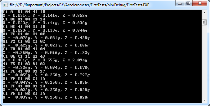
My joy knew no bounds when I finally received the data:
The accelerometer can automatically generate an external interrupt in a variety of cases. We need the simplest event - any sufficiently strong movement. The sensor does this if the following condition is true for any of the axes:
any_motion_thres is set in a special register. Experienced, I found out that at a refresh rate of 25 Hz, the optimal value is 20h. In this scenario, the interrupt flag is set if it is easy to shake the sensor. The flag is automatically removed if the condition stops being fulfilled for some time.
Making sure that all parameters are set optimally, I saved these settings already in the EEPROM. Thus, an accelerometer immediately after switching on will output a logical unit to INT, if there is movement, and SPI is no longer needed.
I chose the ATMEGA8A microcontroller. It has two external interrupts (I decided to use one for the button, and the other for the accelerometer itself), works in the 2.7–5.5V voltage range, and in the deepest sleep mode “power down” consumes only 0.5 µA. It is assumed that the microcontroller will sleep almost all the time, because energy saving is very important. However, to wake up from such a sleep mode, you need to close the INT0 / INT1 foot to the ground, and the accelerometer, if there is motion, on the contrary gives a high level, therefore, to invert, you need to put a transistor. I decided to feed the sensor directly from the legs of the microcontroller itself so that it could be switched on and off without unnecessary losses. The speaker also connected directly. For debugging, it was decided to put one more LED. I did not draw the scheme, and the board in the end looked like this:
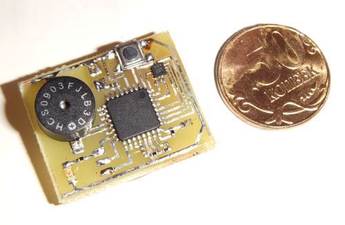
Ready fee:
Alas, I only had a squeaker, which turned out to be more than the board itself:
It's all quite simple. The device has two modes of operation:
The accelerometer, by the way, also has a sleep mode, from which it can wake up at specified intervals, but I decided not to use it in order not to affect the accuracy and reliability. According to the documentation, this sensor consumes 200 μA, this should be enough for many nights.
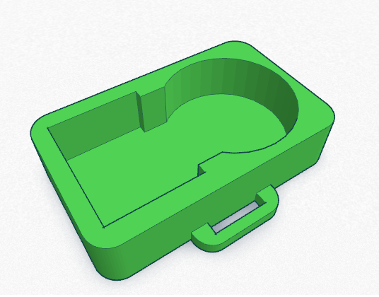
The body was decided to print on a 3D printer.
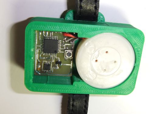
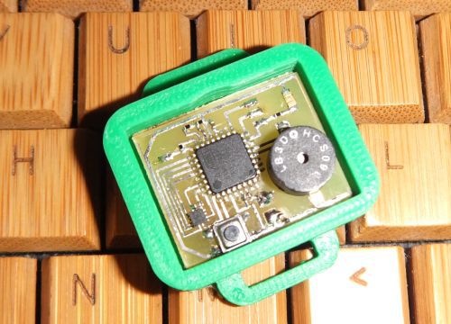
As a result, everything inside looked like this:
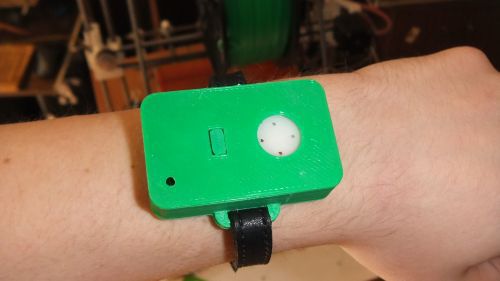
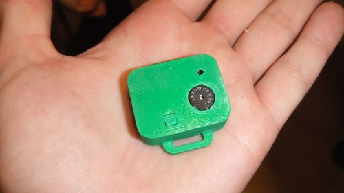
Alas, in the end, the device turned out very cumbersome and collective farm:
But this is still the first experimental sample. I think that later the dimensions and appearance can be greatly optimized. Well, do not forget that even in this form it can save a person's life.
Video devices in operation:
Sorry for dirty fingers, they are still in plastic and ferric chloride.
I foresee certain questions, I will answer them immediately:
As I promised, I could not stop at the first version, especially in the end I was asked to reduce the response time and increase the sensitivity.
Alas, the BMA150 accelerometers were no longer in the store, but there was a BMA250. A quick glance at the datasheet showed that it is even much cooler. True, even less:
Two to two millimeters, with 12 contacts. However, problems with the size and this time did not arise. It is rather even a plus.
This model has a number of very nice settings. And the polarity of the interruption can be specified (goodbye, additional transistor), and their duration, and much more. Yes, it's just great! I was already very happy when I selected the optimal parameters of all the registers, but all the joy disappeared when I realized that the BMA250 does not have the ability to save these settings in the EEPROM. This is such a spoon of tar in a barrel of honey that I could not believe it for a long time.
I had to dissolve on the board and SPI to the accelerometer, so that every time you turn it on, you need to configure it again.
But if you have to change some of the settings, it will not need to be unsoldered. And yes, I listened to the advice in the comments and took advantage of the small piezo squeaker, the battery is placed under the board, as a result, the device has greatly decreased in size. Even when turned on, the voltage on the battery is now measured, and if it is below 2.8V, an additional signal is issued. For this, an ADC with an internal stabilizer of 2.56V and a voltage divider is used to fit into this range.
In the case:
And in closed form:
The most obvious solution is to use an accelerometer. I bought one of the first available - BMA150 from Bosch.
')
Small, contagion, only 3x3mm, but we were not so soldered.
I’ll say at once that I’m doing this exclusively at the amateur level, so don’t criticize much.
After reading the datasheet, it turned out that I²C or SPI can communicate with the accelerometer, but he also has a special conclusion for external interruption. Those. you can configure it once so that under certain conditions it displays a logical unit there. In our case, this is ideal - it is not necessary to constantly interrogate the sensor, it will take the microcontroller out of sleep mode if there is a certain amount of shaking. This is very important, given that you need to make the device as economical as possible in terms of power.
Accelerometer Setup
For experimentation and tuning, I etched the board so that you can easily solder:
For some reason, the accelerometer did not want to work on I²C. It is possible that I was mistaken somewhere. But on SPI it all worked without problems. The sensor is available as an array of memory, which is divided into two parts:
- EEPROM with default settings, i.e. which are used at the time of inclusion
- Operational registers with current settings and sensor readings themselves
My joy knew no bounds when I finally received the data:
The accelerometer can automatically generate an external interrupt in a variety of cases. We need the simplest event - any sufficiently strong movement. The sensor does this if the following condition is true for any of the axes:
|acc(t0)-acc(t0+3/(2*bandwidth))| >= any_motion_thresany_motion_thres is set in a special register. Experienced, I found out that at a refresh rate of 25 Hz, the optimal value is 20h. In this scenario, the interrupt flag is set if it is easy to shake the sensor. The flag is automatically removed if the condition stops being fulfilled for some time.
Making sure that all parameters are set optimally, I saved these settings already in the EEPROM. Thus, an accelerometer immediately after switching on will output a logical unit to INT, if there is movement, and SPI is no longer needed.
Board development
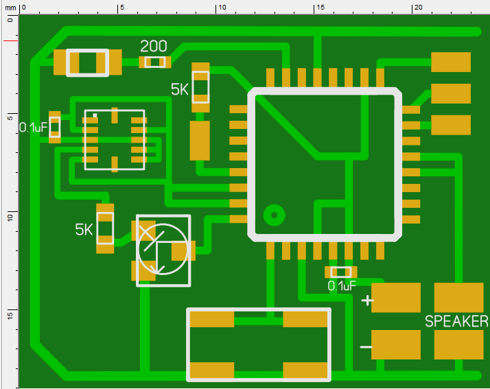
I chose the ATMEGA8A microcontroller. It has two external interrupts (I decided to use one for the button, and the other for the accelerometer itself), works in the 2.7–5.5V voltage range, and in the deepest sleep mode “power down” consumes only 0.5 µA. It is assumed that the microcontroller will sleep almost all the time, because energy saving is very important. However, to wake up from such a sleep mode, you need to close the INT0 / INT1 foot to the ground, and the accelerometer, if there is motion, on the contrary gives a high level, therefore, to invert, you need to put a transistor. I decided to feed the sensor directly from the legs of the microcontroller itself so that it could be switched on and off without unnecessary losses. The speaker also connected directly. For debugging, it was decided to put one more LED. I did not draw the scheme, and the board in the end looked like this:
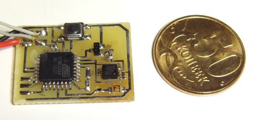
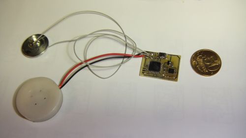
Ready fee:
Alas, I only had a squeaker, which turned out to be more than the board itself:
Firmware
It's all quite simple. The device has two modes of operation:
- Off In this state, we do not power on the accelerometer and wake up only by pressing a button. In this form, the microcontroller can work for at least a year (checked), the discharge of the battery is close to self-discharge.
- Included. When the device is turned on, we power the accelerometer and wake up both from the touch of a button and from the signal from the sensor. If the button is held for one and a half seconds, the device goes back to the off state. If the interruption generated a signal from the sensor, and it repeats within 10 seconds at least once in two seconds, then let us sound the alarm until the button is pressed.
The accelerometer, by the way, also has a sleep mode, from which it can wake up at specified intervals, but I decided not to use it in order not to affect the accuracy and reliability. According to the documentation, this sensor consumes 200 μA, this should be enough for many nights.
Body creation
The body was decided to print on a 3D printer.
As a result, everything inside looked like this:
Alas, in the end, the device turned out very cumbersome and collective farm:
But this is still the first experimental sample. I think that later the dimensions and appearance can be greatly optimized. Well, do not forget that even in this form it can save a person's life.
Video devices in operation:
Sorry for dirty fingers, they are still in plastic and ferric chloride.
I foresee certain questions, I will answer them immediately:
- Yes, this man’s seizures are only in a dream
- Yes, all attacks are accompanied by shaking.
- The button is recessed, so it is difficult to turn off the device by accident
Update 07/07/2014
As I promised, I could not stop at the first version, especially in the end I was asked to reduce the response time and increase the sensitivity.
Alas, the BMA150 accelerometers were no longer in the store, but there was a BMA250. A quick glance at the datasheet showed that it is even much cooler. True, even less:
Two to two millimeters, with 12 contacts. However, problems with the size and this time did not arise. It is rather even a plus.
This model has a number of very nice settings. And the polarity of the interruption can be specified (goodbye, additional transistor), and their duration, and much more. Yes, it's just great! I was already very happy when I selected the optimal parameters of all the registers, but all the joy disappeared when I realized that the BMA250 does not have the ability to save these settings in the EEPROM. This is such a spoon of tar in a barrel of honey that I could not believe it for a long time.
I had to dissolve on the board and SPI to the accelerometer, so that every time you turn it on, you need to configure it again.
But if you have to change some of the settings, it will not need to be unsoldered. And yes, I listened to the advice in the comments and took advantage of the small piezo squeaker, the battery is placed under the board, as a result, the device has greatly decreased in size. Even when turned on, the voltage on the battery is now measured, and if it is below 2.8V, an additional signal is issued. For this, an ADC with an internal stabilizer of 2.56V and a voltage divider is used to fit into this range.
In the case:
And in closed form:
Source: https://habr.com/ru/post/227473/
All Articles