We program the quadcopter on Arduino (a part 1)
Hello, habrozhiteli!
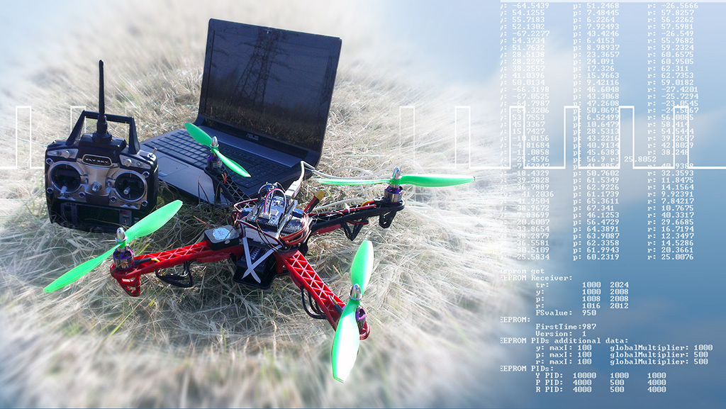
In this series of articles, we will slightly open the quadcopter lid a little more than the hobby requires, and we will also write, configure and launch our own program for the flight controller, which will be the usual Arduino Mega 2560 board.
We have ahead:
- Basic concepts (for beginner copterovodov).
- PID controllers with interactive web-demonstration of operation on a virtual quadcopter.
- Actually the program for Arduino and the tuning program on Qt.
- Dangerous tests of a quadcopter on a rope. The first flights.
- Wreck and loss in the field. Automatic air search using Qt and OpenCV.
- Final successful tests. Summarizing. Where to go?
The material is voluminous, but I will try to keep within 2-3 articles.
Today we are waiting for: a spoiler with a video of how our quadrocopter flew; basic concepts; PID controllers and the practice of selecting their coefficients.
Why all this?
Academic interest, which, incidentally, pursues not only me ( 1 , 2 , 3 ). And, of course, for the soul. I got great pleasure during the work and felt the real inexpressible happiness when “IT” flew with my program :-)For whom?
This material may be interesting, including for people who are far away, or are only going to do multi-rotor systems so far. Now let's talk about the purpose of the basic quadcopter nodes, how they interact with each other, about the basic concepts and about the principles of flight. Of course, all the knowledge that we need, you can find on the network, but you can not force them to seek out on the vast expanses of the Internet.Without prejudice to understanding in basic terms, feel free to skip everything that you know, until the next unfamiliar term in bold , or until an incomprehensible illustration.
NO # 1!
Do not undertake to write your own program for the flight controller, until you try ready-made solutions, which are now quite a lot (Ardupilot, MegapirateNG, MiltiWii, AeroQuad, etc.). First, it is dangerous! To control a quadcopter without a GPS and a barometer, practice is needed, and even more so when it is buggy, turns over, flies not exactly where it should be - and this is almost impossible to avoid during the first tests. Secondly, it will be much easier for you to program, understanding that you need to program and how it should work in the end. Believe me: flight math is only a small part of the program code .NO # 2!
Do not undertake to write your own program for the flight controller, if you are not pursued by academic interest and you only need what ready solutions have been able to do for a long time (fly, photograph, shoot video, fly on mission, etc.) While you write everything, It will take a lot of time, even if you are not alone.Basic concepts
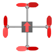
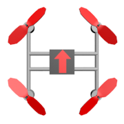
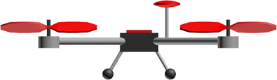
Quadcopters are different, but all of them are united by four rotors:
 |  |  |
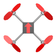 | 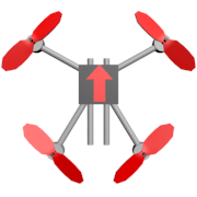 |  |
We will fly on the frame of the X-shaped quadcopter, because I like it more externally. Each design has its own advantages and its purpose. In addition to quadcopters, there are other multicopters. Even if not to consider exotic options, all the same their types - the whole heap!
Let us see how our quadrocopter is arranged inside, and what should the flight controller, which we plan to program, do.
Pitch, roll and yaw angles (pitch, roll, yaw) are the angles that are used to determine and set the orientation of the quadrocopter in space.
Sometimes the word "angle" is omitted and they simply say: pitch, roll, yaw. But according to Wikipedia, this is not entirely accurate. Flight quadcopter in the desired direction is achieved by changing these three angles. For example, in order to fly forward, the quadcopter must bend due to the fact that the rear engines will spin slightly stronger than the front ones:
The quadcopter gas is the arithmetic average between the rotational speeds of all the motors. The more gas, the more the total thrust of the motors, the more they pull the quadcopter up (NOT FORWARD !!! "Slippers on the floor" here means the fastest rise). Usually measured in percent: 0% - the motors are stopped, 100% - rotate at maximum speed. Gas hovering is the minimum level of gas that is necessary so that the quadcopter does not lose height.
Gas, pitch, roll, yaw - if you can control these four parameters, then you can control a quadrocopter. They are sometimes referred to as control channels. If you purchased a dual-channel remote control, you cannot cope with a quadrocopter. Three-channel is more suitable for small helicopters: you can fly without roll control, but on quadcopter it is not convenient. If you want to change flight modes, you will have to fork out for a five-channel console. You want to control the tilt and turn of the camera on board - another plus two channels, although professionals use a separate console for this.
There are many flight modes. Used and GPS, and barometer, and range finder. But we want to implement the basic - stabilization mode ( stab, stabilize , fly in “Staba”), in which the quadcopter holds those angles that are set to it from the console, regardless of external factors. In this mode, when there is no wind, the quadrocopter can hang almost in place. The wind will have to compensate the pilot.
The direction of rotation of the screws is not chosen randomly. If all the motors rotated in one direction, the quadcopter would rotate in the opposite direction due to the generated moments. Therefore, one pair of opposing engines always rotates in one direction, and the other pair in the other. The effect of the occurrence of torques is used to change the yaw angle: one pair of motors begins to rotate a little faster than the other, and now the quadcopter slowly turns to face us (what a horror):
- LFW - left front clockwise rotation (left front, clockwise rotation)
- RFC - right front counter clockwise rotation (right front, counterclockwise rotation)
- LBC - left back counter clockwise rotation (left rear, counterclockwise rotation)
- RBW - right back clockwise rotation (right rear, clockwise rotation)
The speed of the motors is controlled by the flight controller (controller, brains) . This is usually a small board or box with multiple inputs and outputs. There is a huge number of different controllers with a different set of features, different firmware, different tasks. Here are some:

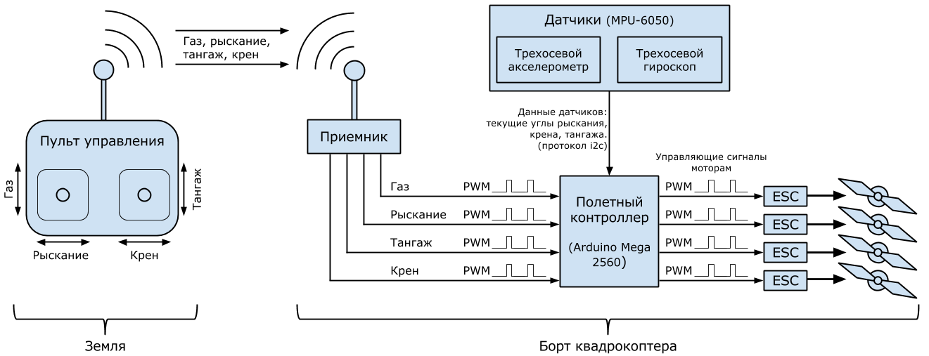
The generalized task of the flight controller is several tens of times per second to perform a control cycle which includes: reading the sensor readings, reading the control channels, processing information and issuing control signals to the motors in order to execute the pilot commands. That is what we are going to program.
There are a lot of different types of sensors that can be used. We will use the three-axis gyroscope and the three-axis accelerometer , which have become almost mandatory in all quadrocopters. Accelerometer measures acceleration, gyroscope measures angular velocity. Thanks to them, the flight controller learns the current angles of pitch, roll and yaw. These sensors are built into the flight controller, and are external. The process of calculating the three angles of the sensor readings is a topic for a separate article. But we don’t need to know this here: the MPU-6050 will do everything for us. This is a small board that performs the necessary calculations and filtering inside and delivers almost ready angles using the i2c protocol. We will have to count them, process them with the rest of the data and issue control signals to the motors.
Motors on multicopters consume large currents, so the flight controller controls them not directly, but through special hardware drivers, called speed regulators ( ESC , regula, esca) . These regulators are powered by the main onboard battery, the control signal is received from the controller, and at the output they have three wires (A, B, C) that go directly to the motors (each motor has its own regulator!)
The “protocol” of communication between the controller and the motor is not as important to us as the “protocol” of communication between the flight controller and the controller, because we have to control the controller from the controller programmatically. There are regulators controlled by i2c, but the most common ones are controlled by a rectangular signal with a minimum of 0 volts and a maximum of 3-5 volts (it is called PWM or PWM , and some argue that PPM is more correct. For more details, for example, here ).
“Protocol” - it says loudly: in order to give the motor a command to rotate at maximum speed, the controller must send pulses with a duration of 2 milliseconds, interspersed with a logical zero of 10 to 20 milliseconds. The pulse duration of 1 millisecond corresponds to stopping the motor, 1.1 ms - 10% of the maximum speed, 1.2 ms - 20%, etc. Practically zero duration does not play any role, only the duration of the pulse itself is important.
For all its seeming simplicity, an ambush lies here: flight controllers are different with different settings, controllers are different, and the minimum (1 ms) and maximum (2 ms) are not universal. Depending on many factors, the range of 1-2 ms may actually be 1.1 - 1.9 ms. In order for the regulator and controller to speak absolutely the same language, there is a procedure for calibrating regulators . During this procedure, the ranges of the regulators change and become equal to the range of the controller. The procedure is sewn into the program of each controller and includes several simple steps (steps may vary depending on the manufacturer - read the instructions!):
- Disconnect the regulator power supply.
- Remove the propeller from the motor.
- Send to the regulator input a signal corresponding to the maximum rotation speed.
- Provide power to the regulator. The motor must remain immobile without assistance.
- Make a pause for 1-2 seconds, wait for a characteristic squeak.
- Send to the regulator input a signal corresponding to the minimum rotation speed.
- Make a pause for 1-2 seconds, wait for a characteristic squeak.
- Disconnect the regulator power supply.
After that, the corresponding interval boundaries will be entered into the controller. If you try to take off with uncalibrated regulators, the consequences can be unexpected: from a sudden jerk of a quadrocopter into the nearest tree to a complete immobility of the motors for any value of gas.
PWM with the same principle uses the on-board receiver . This is a small device that receives radio signals from the ground and transmits them to the flight controller. Most often, the flight controller for each control channel (gas, pitch, roll, etc.) has its own input to which PWM enters. The interaction logic is simple: the command, for example, “70% gas” continuously goes from the ground to the receiver, where it is converted into PWM and goes to the flight controller via a separate wire. Similarly, with pitch, roll, yaw.
Since the relations between the receiver and the controller are their friendly PWM relations, they will also have to be calibrated: the consoles with the receivers are different with their own ranges of operation. The controller must be able to adapt. The procedure for calibrating the radio , in contrast to the calibration of the regulators, we have to create ourselves as part of the flight program. The general calibration plan is:
- Remove the propellers from the motors, just in case.
- In any way, put the controller into radio calibration mode.
- The controller starts the radio calibration for several tens of seconds.
- For the allotted time we move all the stick sticks in all directions until it stops.
- The controller remembers the highs and lows for all control channels in the internal memory for centuries.
In addition to the program for the flight controller, another program is needed: the flight controller setup interface . Most often, it is a PC program that connects to the flight controller via USB and allows the user to set up and check the flight program, for example: start the radio calibration, adjust the stabilization parameters, check the sensors, set the flight route on the map, determine the multicopter behavior when the signal is lost and much more. We will write our customization interface in C ++ and Qt as a console utility. Here it is, if you look into the future:

No one is immune from accidents. Even ten-inch plastic screws on small motors can leave bloody bruises on the skin, which will hurt for another week (checked personally). Elementary make yourself a new make-up and hairstyle, if you hook the stick of gas on the remote, while you carry on the included quadrocopter. Therefore, the flight controller should provide at least some security: the armed / disarmed mechanism . The status of the quadcopter "disarmed" means that the motors are turned off and even the full throttle command from the console has no effect, although the power is on. The “armed” status of the quadcopter means that the commands from the console are executed by the flight controller. In this state, quadrocopters take off, fly and land. The quadcopter turns on and should immediately get into the disarmed state in case the inattentive pilot turns it on when the gas stick on the console is not at zero. In order to transfer the rotor to the “armed” state, the pilot needs to make some pre-specified gestures from the console. Often this gesture is to hold the left stick in the lower right corner (gas = 0%, yaw = 100%) for a couple of seconds. After that, the flight controller makes at least a minimal self-test and, if it is successfully passed, it “ armies ” (ready for flight!) With another gesture (gas = 0%, yaw = 0%) the quadcopter is “ disarming ”. Another good security measure is autodisarm , if the gas was at zero for 2-3 seconds.
About motors, batteries, regulators, propellers
The choice of components for a multicopter is a topic for a whole series of articles. If you are going to make your first quadcopter - state what you need it for, and use the tips of experienced ones or take the list of components that someone else has compiled and successfully fly on it.
And yet for the general understanding it is useful to know the main points.
Among the fans and professionals of multi-rotor systems, the most common are lithium-polymer batteries, as the main sources of power for on-board electronics and motors. They are distinguished by capacitance, voltage and maximum current output. Capacity, as usual, is measured in ampere hours or milliampere hours. Voltage is measured in the number of "cans" of the battery. One "bank" - an average of 3.7 volts. Fully charged "bank" - 4.2 volts. Most common are batteries with cans ranging from three to six. Maximum current output is measured in amperes, and is marked, for example, like this: 25C. C - battery capacity, 25 - multiplier. If the capacity is 5 amps, then this battery can give 25 * 5 = 125 amps. Of course, the current output parameter is better to take with a margin, but, basically, the larger it is, the more expensive the battery is. Marking example: 25C 3S 4500mah.
Each can is a separate battery. All of them are soldered consistently. In order to evenly charge all the banks, a balancing connector is provided with access to each bank separately, and special chargers are used.
The main parameter of the brushless motor is its kv. This is the number of revolutions per minute for every volt of applied voltage. The most common motors with kv from 300 to 1100. Kv closer to 1000 is usually chosen for small quadcopters (1-2 kilograms plus 500 grams of payload) and put on them plastic propellers up to 12 inches in diameter. On large multicopters (for raising good and heavy photo-video equipment) or for long periods (for flight time records) there are usually low-kv (300-500) motors and huge carbon propellers (15-20 inches in diameter). Kv is not the only important parameter of the motor: you can often find complete tables of motor power and thrust from the supplied voltage and the type of propeller installed. In addition, each motor is designed for its own voltage range (number of battery cans) and its maximum current. If the manufacturer writes 3-4S, do not use it with 5S batteries. The same goes for regulators.
If the motor is rated for current up to 30A, then the controller should rely on current up to 30 + 10A to prevent overheating. Poor-quality or unsuitable regulators can cause the so-called "sync failures" and stop the engine in flight, and you will learn another multi-rotor term: " caught the planet ." Another important point is the thickness and quality of the wires. Incorrectly calculated wire cross-section or a poor connector can cause a fire in the air.
As you can see, there are a lot of nuances. I haven’t even listed half, so it’s quite difficult to choose the components for the first multicopter myself.
And yet for the general understanding it is useful to know the main points.
Batteries
Among the fans and professionals of multi-rotor systems, the most common are lithium-polymer batteries, as the main sources of power for on-board electronics and motors. They are distinguished by capacitance, voltage and maximum current output. Capacity, as usual, is measured in ampere hours or milliampere hours. Voltage is measured in the number of "cans" of the battery. One "bank" - an average of 3.7 volts. Fully charged "bank" - 4.2 volts. Most common are batteries with cans ranging from three to six. Maximum current output is measured in amperes, and is marked, for example, like this: 25C. C - battery capacity, 25 - multiplier. If the capacity is 5 amps, then this battery can give 25 * 5 = 125 amps. Of course, the current output parameter is better to take with a margin, but, basically, the larger it is, the more expensive the battery is. Marking example: 25C 3S 4500mah.
Each can is a separate battery. All of them are soldered consistently. In order to evenly charge all the banks, a balancing connector is provided with access to each bank separately, and special chargers are used.
Motors, propellers, regulators
The main parameter of the brushless motor is its kv. This is the number of revolutions per minute for every volt of applied voltage. The most common motors with kv from 300 to 1100. Kv closer to 1000 is usually chosen for small quadcopters (1-2 kilograms plus 500 grams of payload) and put on them plastic propellers up to 12 inches in diameter. On large multicopters (for raising good and heavy photo-video equipment) or for long periods (for flight time records) there are usually low-kv (300-500) motors and huge carbon propellers (15-20 inches in diameter). Kv is not the only important parameter of the motor: you can often find complete tables of motor power and thrust from the supplied voltage and the type of propeller installed. In addition, each motor is designed for its own voltage range (number of battery cans) and its maximum current. If the manufacturer writes 3-4S, do not use it with 5S batteries. The same goes for regulators.
If the motor is rated for current up to 30A, then the controller should rely on current up to 30 + 10A to prevent overheating. Poor-quality or unsuitable regulators can cause the so-called "sync failures" and stop the engine in flight, and you will learn another multi-rotor term: " caught the planet ." Another important point is the thickness and quality of the wires. Incorrectly calculated wire cross-section or a poor connector can cause a fire in the air.
As you can see, there are a lot of nuances. I haven’t even listed half, so it’s quite difficult to choose the components for the first multicopter myself.
Stabilization mathematics, PID controllers (PID)
If you decide to do multi-copters, then sooner or later you will have to face the PID controller setting, since this mathematical device is used in almost all stabilization tasks: stabilizing quadrocopter angles in the air, flying and holding the GPS position, keeping the barometer altitude, brushless gear camera stabilization in flight (camera mount).
You get a two-axis camera suspension, put GoPro there, for example, turn on and instead of stabilization get convulsions, vibrations and twitching, although all sensors are calibrated and mechanical problems are eliminated. The reason is incorrect PID parameters.
You collect a multicopter, calibrate sensors, regulators, radio, check everything, try to take off, and it is so dull in the air that it even turns it over with a light breeze. Or vice versa: it is so sharp that it suddenly takes off and twists a triple flip without permission. The reason is the same: the parameters of the PID controllers.
For many devices using PID controllers, there are instructions for tuning, and even a few in addition to numerous video constructions from the users themselves. But to make it easier to navigate this variety, it is useful to understand how these regulators are arranged inside. In addition, we are going to write our own quadcopter stabilization system! I propose, together with me, to “reinvent” and “on the fingers” again understand the formula of the PID controller. For those who prefer dry math language, I recommend Wikipedia, an English article , because Russian is not yet described in such detail.
We will consider the quadcopter in two-dimensional space, where it has only one angle - the roll angle, and two motors: left and right.
The flight controller continuously receives commands from the ground: “roll 30 degrees”, “roll -10 degrees”, “roll 0 degrees (keep horizon)”; its task is to perform them as quickly and accurately as possible with the help of motors, taking into account: wind, uneven weight distribution of the quadrocopter, uneven wear of the motors, inertia of the quadrocopter, etc. Thus, the flight controller must continuously solve the problem, what speed of rotation to apply to each motor, taking into account the current value of the angle of heel and the required one.Continuously - this, of course, loudly said. It all depends on the computational capabilities of a particular iron. On Adruino, it is quite possible to fit one iteration of the processing and control cycle in 10 milliseconds. This means that every 10 milliseconds the readings of the angles of the quadrocopter will be read, and on their basis, control signals will be sent to the motors. These 10 milliseconds are called the adjustment period . It is clear that the smaller it is, the more often and more precisely the regulation occurs.
The gas level flows from the receiver to the controller. Denote it
 .Let me remind you that this is the arithmetic average between the speeds of rotation of all motors, expressed as a percentage of the maximum speed of rotation. If a
 and
and  - rotational speeds of the left and right motors, then:

Where
 - quadcopter reaction (force), which creates a torque due to the fact that the left motor rotates at a faster rate than the gas, and the right one - at the same rate slower. may take negative values, then the right motor will spin faster. If we learn to calculate this value at each iteration of the processing cycle, then we will be able to control a quadcopter. It is clear that as a minimum, must depend on the current angle of heel (
  ) and the desired angle of heel (
  ) that comes from the control panel.
Imagine a situation: the command “keep the horizon” (
= 0) is received , and the quadrocopter has a roll to the left: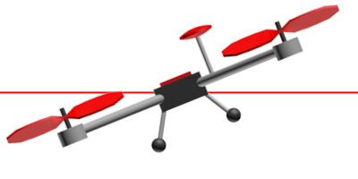
 - the difference (error) between and which the controller seeks to minimize.
The greater the difference between the desired roll angle and the current angle, the stronger the response should be, the faster the left motor should spin relative to the right one. If this is written using our notation:
Here P is the proportionality coefficient. The larger it is, the stronger the reaction will be, the sharper the quadcopter will react to the deviation from the required roll angle. This intuitive and simple formula describes the operation of a proportional controller . The essence is elementary: the more the quadrocopter deviates from the required position, the more one should try to return it. Unfortunately, this formula will have to complicate. The main reason is overshoot.
For several tens of milliseconds (several iterations of the processing cycle) under the influence of a proportional regulator, the quadrocopter will return to the desired (in this case, horizontal) position. All this time, error
and effort will have the same sign, although it will become smaller and smaller. Having gained some kind of rotation speed (angular speed), the quadrocopter will simply roll over on the other side, because no one will stop it in the desired position. It is the same as a spring, which always seeks to return to the initial position, but if it is pulled back and released, it will fluctuate until friction takes over. Of course, friction will also act on a quadcopter, but practice shows that it is not enough.For this reason, one more term should be added to the proportional regulator, which will slow down the quadcopter rotation and prevent overshooting (overloading in the opposite direction) - a kind of friction imitation in a viscous medium: the faster the quadcopter turns, the more reasonable limits. The rotational speed (the rate of change of the error) is denoted as
 , then:
where D is the adjustable coefficient: the larger it is, the stronger the stopping force. Vague memories emerge from the school physics course that the rate of change of any quantity is a derivative of this quantity over time:
 .
.And here the proportional regulator turns into a proportional-differential (proportional term and differential):
 .
.The error is
easy to calculate, because at each iteration we know and ;P and D - customizable parameters before launch. To calculate the derivative (rate of change ), it is necessary to store the previous value , know the current value and know the time elapsed between measurements (adjustment period). And here it is - the physics of the sixth grade of the school (speed = distance / time): .
. - the period of regulation;
  - error value from the previous iteration of the regulation cycle. By the way, this formula is the simplest method of numerical differentiation, and it is quite suitable for us here.
Now we have a proportional-differential controller in a flat “biccopter”, but another problem remains. Let the left edge weigh a little more than the right, or, equivalently, the left engine works a little worse than the right one. The quadcopter is slightly tilted to the left and does not rotate back: the differential term is zero, and the proportional term takes a positive value, but it is not enough to return the quadrocopter to the horizontal position, because the left edge weighs slightly more than the right one. As a result, the quadcopter will always pull to the left.
A mechanism is needed to track such deviations and correct them. A characteristic feature of such errors is that they manifest themselves over time. The integral component comes to the rescue. It stores the sum of all errors
for all iterations of the processing cycle. How does this help? If the proportional term is not enough to correct a small error, but it is still there - gradually, over time, the integral term is gaining strength, increasing the response and the quadrocopter takes the required angle of heel.There is a nuance. Suppose
equal to 1 degree, the regulation cycle - 0.1 s. Then in one second the sum of errors will take the value of 10 degrees. And if the processing cycle is 0.01s, then the amount will reach as much as 100 degrees. So that for the same time the integral term should gain the same value for different periods of regulation, the resulting amount will be multiplied by the period of regulation itself. It is easy to calculate that in both cases from the example we get the sum of 1 degree. Here it is - an integral term (for the time being without a tunable coefficient): .
.This formula is nothing more than the numerical integral over the time of a function
in the interval from zero to the current moment. That is why the term is called integral: ,
,where T is the current time.
It's time to write the final formula of the proportional-intergral-differential controller:
 ,
,Where
 - one of the adjustable parameters, which are now three:
  . This formula is convenient to use from the program code, but the formula, which is given in the textbooks:
 .
.There are several variations of it, for example, you can limit the module of the integral term so that it does not exceed a certain allowable threshold (we will do so).
Practice
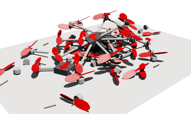
Well, now it's time to practice the selection of coefficients. Readers are invited to a JavaScript-page with a virtual quadrocopter, which he has already seen in the pictures: selection of parameters of the PID controller for a quadrocopter ( JSFiddle). When you first start the overshoot is immediately visible - fluctuations around the desired position. When the oscillations stop, you can observe the effect that the proportional coefficient does not cope with the error due to the "asymmetrical" quadrocopter (set by tick "Asymmetry"). The parameters P, I, D are available for setting. Now you know what to do with them. "Scrolling" under the quadrocopter can control the desired value of the roll. "Interval (ms):" - regulation interval. Reducing it is “cheating”, but it’s very useful to see how it affects the quality of stabilization.For lovers of "pure" mathematics, you can offer to configure an abstract PID controller
The entered parameters are not automatically applied: you need to click “Apply”. A couple of small tips: if it seems to you that the quadcopter is too slow to respond to control, you can increase P, but too much P can result in overshoot. Parameter D will help with overshoot, but too large values will lead to frequent fluctuations, or again overshoot. The parameter I is usually 10 - 100 times smaller than the parameter P since its power is in accumulation in time, not in quick response.
Manual tuning of PID parameters requires practice. There are analytical methods for calculating them, but they require good preparation and accurate knowledge of many parameters of a particular tunable system. As an average between manual selection and analytical calculation, there is a wide range of empirical methods proposed by various researchers.
In our 2D quadcopter, only one angle changes - the roll angle. In a tuning 3D quadcopter, three independent PID regulators will be required for each of the corners, and the control of a specific motor will represent the sum of the efforts for all the regulators.
Conclusion of the first part
In this article, we got acquainted with the basic concepts: quadrocopter and flight principle, pitch, roll, yaw, gas, gas hovering, stabilize flight mode, flight controller, gyroscope, accelerometer, speed controller, PWM, controller calibration, radio calibration, onboard receiver, interface settings for the flight controller, armed / disarmed, autodisarm .After this, we re-invented the PID controller formula by slightly touching on the numerical differentiation and integration , and we experienced how to adjust the P, I, D parameters on the virtual quadrocopter .
Now, if you own a lightsaber-programming, you can start your quadcopter stabilization program, or, better yet, join in with fresh ideas to existing open source projects. Well, I will,
In conclusion of this part, I just have to mention the person who helped me in choosing the components and setting up the most difficult (first!) Quadrocopter on the MegapirateNG firmware and patiently answered hundreds of questions on these very basic concepts: SovGVD , thank you! :-)
As a reward to those who were able to squander this entire sheet, I spread the promised small video, like our quadrocopter with our “invented” PID controllers, on our program for Arduino Mega 2560 flies:
Of course, it lacks GPS, as in commercial and mass products, a little lack of stability, but on the other hand - OUR, and we know it up and down to the last factor with an integral factor! And it is really cool that such technologies are available to us today.
Isn't it a great time we live ?!
')
Source: https://habr.com/ru/post/227425/
All Articles