Introduction to Renesas microcontrollers using the RL78 line as an example
If the average Russian-speaking developer of microcontroller electronics is asked to name 3-5 best known or major manufacturers of microcontrollers, it is most likely to hear in response such names as Microchip, Atmel, TI, or STM. Someone will also call NXP, Freescale, Samsung or Fujitsu. But few people will remember another producer who is almost unknown in the post-Soviet space.
We are talking about the Japanese company Renesas Electronics, which, meanwhile, in its annual reports boasts such an interesting infographic ...

General application microcontrollers: microcontrollers for various applications, excluding automotive electronics
Thus, the "dark horse", the products of which will be discussed below, is the leader of the global market for both general-purpose microcontrollers and the automotive electronics market, and has every right to call itself "the world's No. 1 microcontroller supplier." The secret of this company's success is simple: Renesas Technology appeared in 2003 as a joint venture between Hitachi and Mitsubishi, and in 2010 they were also joined by Nec Electronics, forming a joint venture of Renesas Electronics.
The result of this cooperation is the possibility of using the well-established cores of the three companies together with effective specialized peripherals:
- From Hitachi, H8, H8S, H8SX and SuperH cores were used.
- From Mitsubishi, M16 / M32, R32, 720 and 740 cores fell into the hands of developers.
- From NEC - the V850 and 78K line of cores.
Having received such a number of developments, Renesas began to develop new lines using technologies available to participating companies. To replace the Hitachi H8SX and Mitsubishi R32C came a line of 32-bit RX microcontrollers. As a successor to the popular NEC V850, the RH850 was developed - a line of microprocessors for use in automotive electronics. The R8C core was also developed as a solution of the lower price range, compatible with the Mitsubishi M16C.
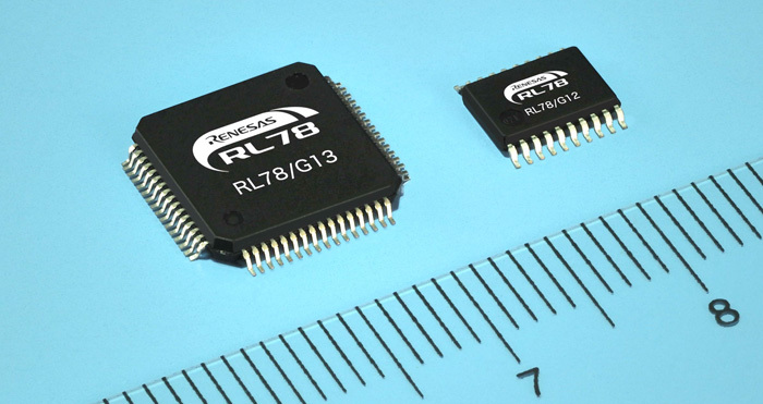
The first independent development of Renesas after unification with NEC was the new 16-bit RL78 core with CISC architecture. In it, the developers tried to combine the positive sides of the R8C and 78K0 in the same family. At the moment, the family can be divided into 5 "branches" for various applications:
- RL78 / G1x - general purpose microcontrollers: up to 28 channels ADC, DAC, USB, I2C, SPI, PWM, RTCC.
- RL78 / L1x - LCD control microcontrollers: support USB 2.0, control LCD indicators up to 4x53 / 8x48 segments.
- RL78 / F1x - microcontrollers for the automotive industry: CAN interface support, engine management, extended temperature range up to +150 ºC.
- RL78 / D1x - microcontrollers for instrument making: 4-channel stepper motor controller out-of-the-box, LCD control of up to 4x53 segments, CAN.
- RL78 / I1x - microcontrollers for lighting control: DALI / DMX512, PWM.
The range of RL78 microcontrollers is simply huge, it is easy to find a model that is suitable for a specific use. Controllers of all families boast the presence of DMA lines, ADC / DAC converters, support for I2C and SPI interfaces, as well as support for operation in an industrial LIN network.
The CIS pipeline of the RL78 core consists of 3 stages, about 86% of instructions can be executed in 1–2 processor cycles. It also supports hardware execution of MAC commands 16x16 bits.
As the main advantage of the microcontroller RL78, the manufacturer claims minimal power consumption, calling the line no less than true low power (really low power consumption). Despite this, we can note the preservation of high performance and a wide range of operating voltages.
For clarity, we will summarize in the general table the key characteristics of this controller and the main competitors from the “popular” brands:
Comparison of characteristics of popular microcontrollers
STM8L | STM32L | PIC24 Lite | MSP430 | RL78 | |
Digit | 8 bit | 32 bits | 16 bits | 16 bits | 16 bits |
Performance | ~ 1 DMIPS / MHz, 16 MHz max | ~ 1.04 DMIPS / MHz, 32 MHz max | ~ 0.5 MIPS / MHz, 32 MHz max | ~ 1 DMIPS / MHz, 25 MHz max | ~ 1.3 DMIPS / MHz, 32 MHz max |
Flash | 2-64 KB | 32-384 KB | 16-32 KB | 0.5-512 KB | 0.125-512 KB |
Ram | 1-4 KB | 4-48 KB | 1-2 KB | 0.125-66 KB | 1-32 KB |
Slave consumption | 150-180 μA / MHz | 214-230 μA / MHz | 195-350 μA / MHz | 80-280 μA / MHz | 46-156.25 μA / MHz |
Sleep consumption + rtc | 1,3 μA | 0.9 μA | 0.5-0.7 μA | 0.7 μA | 0.56-0.68 μA |
Power range | 1.65-3.6 V | 1.65-3.6 V | 1.8-3.6 / 2.0-5.5 V | 1.65-3.6 B | 1.6-5.5 V |
Approximate price range | 0.5-4.5 $ | 1,5-7,7 $ | 0,8-4,2 $ | 0,34-9,5 $ | $ 0.68-8 |
The periphery is deliberately not mentioned in this table, but even here the advantage is definitely not in favor of the competitors - traditionally everything is very good with the periphery of Renesas.
As for the useful features of some representatives of the line, the following can be noted:
- Data transfer control - the ability to transfer data between peripheral modules without a processor.
- Event link controller - exchange interrupts between peripheral modules without the participation of the processor.
- Flash memory with ECC.
- LVD - low voltage detection.
- Ability to issue up to 20 mA per GPIO pin, 5V-tolerant pins.
It all sounds good and beautiful, but are Renesas microcontrollers comfortable when developing? To check this, let's take the Renesas YRPBRL78G13 debug board and try to evaluate the entry threshold for using Renesas RL78 series microcontrollers.
The “on board” board is equipped with the R5F100LEAFB microcontroller, which belongs to the RL78 / G13 family: 64 KB of flash-memory, 4 KB of RAM, and 4 KB of flash-memory with an increased number of overwrites for storing data are also allocated. The built-in ADC on 12 channels provides resolution up to 10 bits, and DMA on 2 channels will help to store the received data in memory. Fourteen timers channels, seven PWM channels, three UARTs and seven I2Cs are quite good for a “kid” in the LFQFP64 package for $ 1.64 (albeit in batches of 1000 pieces).
This board is attributed by Renesas to the demo section (promotion boards), so its retail price is $ 25. In fairness, this is not the most interesting offer of the company, the debug board YRPBRL78L12 on RL78 / L12 is currently offered for only $ 10. For those who wish, there is also a large number of large, “adult” debugs.
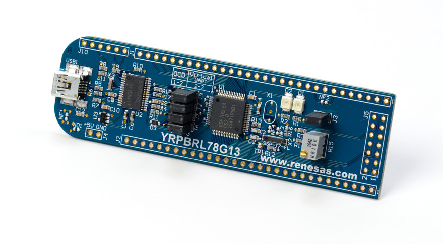
Debug board Renesas YRPBRL78G13
The board is made in a compact form factor of 100x30 mm and, in addition to the controller itself, the RL78 / G13 contains a hardware debugger that allows not only to flash the board via USB, but also to perform in-circuit debugging in real time. The board provides power from both the USB bus and from an external power source.
Renesas YRPBRL78G13 Debug Card
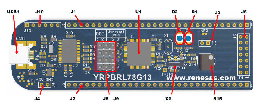
The external power supply (+ 5V) can be directly connected to the board using the J4 connector, while the adjacent pads must be re-connected. Using jumpers J6 – J9, you can choose to decide the USB port, OCD (On Chip Debug) or Virtual UART (a COM port emulator via USB using the optional 8-bit μPD78F0730 controller of the previously mentioned 78K0 family). Virtual UART, however, is not always convenient to use because of the need to constantly rearrange jumpers when debugging. If necessary, you can use the external debugger Renesas E1, connected via the connector J5.
On the long lines J1 and J2 almost all pins of the microcontroller are derived. Connector J10 is used to flash an auxiliary controller 78K0 in production. To control the power consumption of the microcontroller, power is supplied to it via jumper J3.
There are also two LEDs on the board (power indicator and user LED) and a potentiometer connected to a 10-bit ADC microcontroller. Interestingly, a small screwdriver comes with the board for adjusting the potentiometer.
So, with the hardware, everything is clear, now let's see what Renesas offers to software developers.
Development begins with documentation, and here Renesas can be called an example to follow: the specification can be found in free access without any problems, and most often there are no problems with their relevance and completeness - the volume of documentation can even frighten the uninitiated person. The manufacturer traditionally pays special attention to the description of the periphery and application notes (application notes). Due to the prevalence, Renesas also has its online community with the modest name Renesas Rulz.
RL78 c language. As a development environment, the beloved IAR Embedded Workbench with support for RL78 (version EWRL78) is offered by many, traditionally there is its free version KickStart edition with a code size limit of 16 KB. The C-SPY debugger built into IAR is fully supported: you can set breakpoints and freely walk through the code with a view of registers / variables. It is also possible to use e² studio (eclipse embedded studio) with the GDB debugger, as well as many other utilities as the development environment.
The firmware code can be written both for bare metal and using RTOS: the manufacturer suggests using FreeRTOS, CMX-RTX, Micrium μC / OS, OSEK Run Time Interface (ORTI), Express Logic or Segger embOS implementations. For home automation lovers, there is a KNX stack implementation.
To fill the firmware in the controller, there are many applications, such as the free utility WriteEZ5. This utility is universal: to support a certain model of the microcontroller, simply download the appropriate configuration file in pr5 format and point the program at it before flashing.
The most interesting approach from the point of view of developing software code Renesas demonstrates with its graphical utility Applilet. This utility allows you to configure all the peripherals, gpio, interrupt subsystem and ADC / DAC modes used by the microcontroller in a convenient human-readable form, and then, based on this configuration, generate initialization code and stubs for all event handlers. The generated code can then be used as the basis of the project and, subject to the rules for organizing the code (see below), at any time have the opportunity to change the configuration of the finished project.
Such an approach will allow concentrating on the application logic, initialization of the periphery and the API for its management, the code generated by the utility will take over. There is no need to deal with monstrous libraries of work with peripherals, as is often the case with other vendors, and the generated code is guaranteed to contain a minimum of redundancy.
Thus, the entry threshold for the RL78 is significantly reduced, even a developer without microcontroller programming experience will be able to write simple firmware in minimal time.
As an example, we will show how to write a traditional Hello world from the world of microcontrollers - we blink a LED. And so that it is not so boring, we will blink for a reason, and using pulse-width modulation and timers to smoothly turn on and off the LED. In total, we will need 3 timers - 2 of them will be used for PIM, and for the third we will smoothly change the pulse duty cycle, which in our case will lead to a change in brightness.
Let's open the Applilet utility from Renesas and create a new project for the R5F100LEAFB controller:

New project in the Applilet3 for RL78 / G13 utility window
This is how the Applilet utility window of the currently currently running version 3 looks like, opened on the tab of the zero channel timer settings. When using the appropriate mode of operation, channel 0 is reserved for the timer, which defines the PIMA period, so it does not abound in settings. When the INTTM00 interrupt is enabled, exactly like any other interrupt from the periphery, the “stub” code of the interrupt will be automatically added (and initialized) to the code generated by the utility.
Channel 1 directly specifies the active part of the period, so on the tab of its configuration, you can set the width of the active level (as a percentage of the period of channel 0) and the level settings:

Channel 1 settings in Applilet3 for RL78 / G13 utility window
We also need the so-called interval timer, which will generate an interrupt every 0.2 seconds. Its configuration is also reduced to a pair of ticks in the Applilet utility interface.
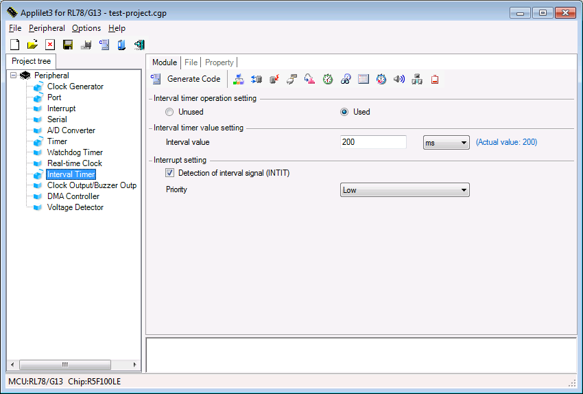
Setting the interval timer in the Applilet3 for RL78 / G13 utility window
And of course, we will need to transfer the P77 pin, to which our LED is connected, to the output mode.
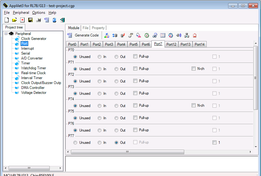
Set pin P77in the Applilet3 for RL78 / G13 utility window
You can stop at this, save the project and press the cherished button Generate code (generate code). We will use IAR as the development environment.
Let's look at the files of the generated project:
r_cg_cgc.c
r_cg_cgc_user.c
r_cg_it.c
r_cg_it_user.c
r_cg_port.c
r_cg_port_user.c
r_cg_timer.c
r_cg_timer_user.c
r_main.c
r_systeminit.c
As can be understood from their names, the entire code is divided into modules according to the functions performed: clock generator, interval timer, gpio, timers, as well as the main program loop (empty in our case) and the low-level controller initialization code. Files of the form * _user.c contain stubs of event handlers of the corresponding periphery.
Open the r_cg_it_user.c file and modify the interval timer handler. Each call to the handler will be made to reduce or increase the duty cycle of the PWM by an amount specified by the number of STEPS_NUM steps. When the maximum or minimum is reached, the direction of the change in brightness is reversed.
#pragma vector = INTIT_vect __interrupt static void r_it_interrupt(void) { /* Start user code. Do not edit comment generated here */ int16_t TDR0_value, TDR1_value, step; R_TAU0_Channel0_Stop(); TDR0_value = TDR00; TDR1_value = TDR01; step = TDR0_value / STEPS_NUM; if (moving_up == 1) { if (TDR1_value > TDR0_value - step) moving_up = 0; else TDR1_value += step; } else { if (TDR1_value < step) moving_up = 1; else TDR1_value -= step; } TDR01 = TDR1_value; R_TAU0_Channel0_Start(); /* End user code. Do not edit comment generated here */ } As it is easy to see, the generated project is replete with comments intended to separate the automatically generated and user-written code. If you comply with these limits and save comments, you can change the peripheral settings using the Applilet utility at any time without losing the existing user code of the project.
The only thing left for us to add to the project is the connection between the state of PWM and the pin P77 to which the LED is connected. To do this, when the interruption of channel 0 of the timer is triggered, we set the controller's foot to one:
#pragma vector = INTTM00_vect __interrupt static void r_tau0_channel0_interrupt(void) { /* Start user code. Do not edit comment generated here */ P7_bit.no7 |= 1; /* End user code. Do not edit comment generated here */ } And for channel 1, reset this value to zero:
#pragma vector = INTTM01_vect __interrupt static void r_tau0_channel1_interrupt(void) { /* Start user code. Do not edit comment generated here */ P7_bit.no7 &= 0; /* End user code. Do not edit comment generated here */ } Everything is ready: we compile the project, fill it into the controller using the WriteEZ utility and, moving the jumpers on our debug board from debug mode to the operating mode, observe how the LED on the board slowly and smoothly turns on and off, as required.
Using the shown approach, the internal features of the Renesas RL78 series microcontrollers remained behind the scenes for us, which may not satisfy the needs of demanding developers when implementing complex projects, but for simple work algorithms, using automatic generation of an initialization code for an extensive list of peripherals of Renesas RL78 controllers can significantly reduce time, and therefore the cost of developing devices with ultra-low power consumption.
Questions and comments are welcome.
PS This article was published in a new issue of the printed magazine "Herald of Electronics". More information about other electronic components and technologies that we use to develop electronics can be found on the Promwad team website in the “Technologies” section.
')
Source: https://habr.com/ru/post/227409/
All Articles