Intellectual SKS in Russian
Hello honorable ladies and gentlemen.
About intelligent SCS - or otherwise intellectual systems of physical layer management (Intelligent Physical Layer Management Solution, IPLMS), cable infrastructure management systems, interactive management systems (SIU) - a lot has been written. I want to raise this topic again, because I intend to talk about intellectual SCS, built on the basis of Russian inventions.
Details below.
For a start, a small digression on the already existing solutions, so that it would be clear why to create another one.
There are two ways to organize SCS (structured cable systems) - interconnect and cross-connect. Let's start with the latter, since it dominates in the world of intelligent SCS (in my opinion, just because there are no normal solutions for interconnect).
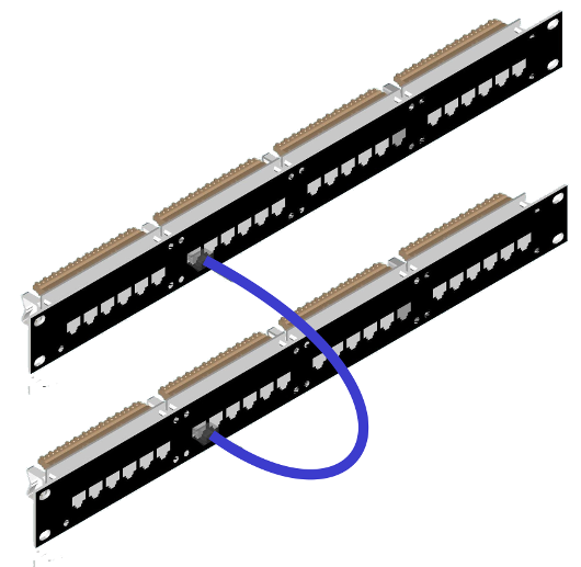
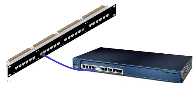
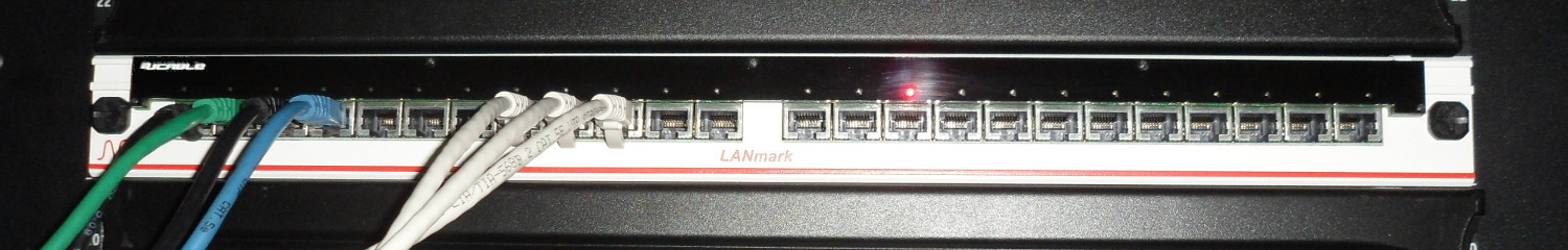
Cross-connect is when using patch cords connect the ports of two patch panels, as in the picture.
The task of the intelligent SCS is to automatically track the actual connection of the pairs of ports of the patch panels to each other. Very briefly about what is currently on the market.
1. iPatch — Patch panel ports have sensors that trigger when there is an RJ45 connector in a panel port.
2. Many options (founder of RiT), when two or one additional conductor are added to the patch cord, and additional contacts are added to the connectors. This additional communication channel is used to track connections. By the way, in the description of one of its patents, RiT suggested using an STP patch cord for an additional communication channel.
3. The MIIM system, by analogy, uses an unused bandwidth of a patch cord as an additional channel. That is, it transmits DC signals along the core of the patch cord between the panels to track switching.
4. It makes sense to use RFID tags to identify the connector. The scheme is simple: each port of the patch panel has a small RFID antenna, and an RFID tag is installed on the RJ45. When RJ45 is connected to a port, the antenna reads its identifier. Example, Future-Patch.
5. Similarly, instead of an RFID tag for identification, you can use a contact identification chip based on 1-Wire, as implemented in Quareo.
Now about the solutions offered by the Russian company Ucable. Since solutions were developed for installation on any patch panels, without being tied to the panel manufacturer, and the ports on different panels have different locations, several technical tricks were used to place the sensors.
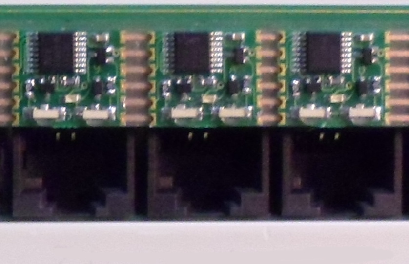
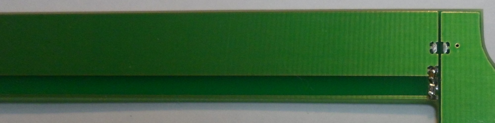
On the mini boards were installed a pair of IR-diode - phototransistor. Thus, we have a sensor that detects the presence of RJ45 in the port of the patch panel (as in iPatch). And the mini-boards themselves are glued to a long printed circuit board with a bus using an adhesive tape with anisotropic electrical conductivity. Thus, sensors can be installed on a patch panel with an arbitrary port allocation.
Additionally, if desired, an RFID antenna can be mounted behind the mentioned length of the board. Since we do not know the location of the ports, one of the options is to make many, many RFID antennas in front of each potential port location for the patch panel (as competitors wish). But it seems that in Russia long (445 mm) multilayer printed circuit boards have not yet been learned to do, and the design of the board is complex. Therefore, a simple RFID antenna was used in the form of a PCB conductor placed directly above the ports of the patch panel.
She reads in a crowd all the labels on the connectors connected to the panel. It is clear that the port number to which Rj45 is connected is not so determined, but for this purpose there are IR sensors. As soon as a connector is inserted into the port, we use the IR sensor to determine the port, and the appearance of a new identifier among the many RFID tags allows us to identify the RJ45 and, accordingly, the patch cord.
For connectors, serial RFID tags are used, which in China are sold wholesale at $ 0.1
')
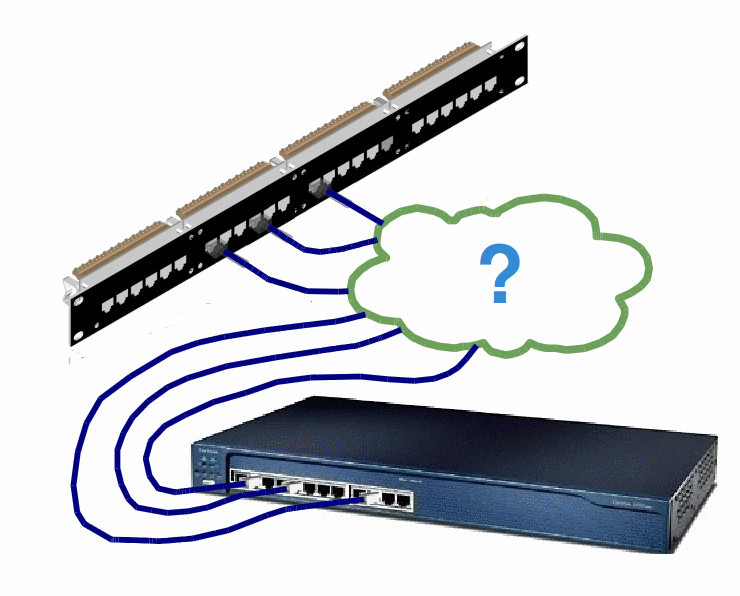
Let's move on to another scheme for building the SCS. For SCS built according to the inter-connect scheme, when the patch panel ports are connected directly to the switch ports, today you can use the following options:
1. Equip the switchboard with the same sensors (somehow hung from above) as the patch panel (variants are described in the cross-connect scheme).
2. Panduit does this. It uses a special patch cord with an additional core, which helps to track the electrical connection with the screen contact of the switch port. First, connect the cord to the required switch port, then plug the other end of the patch cord into the additional service port of the patch panel equipped with 100Base-T (theoretically, any Ethnernet port can be used). By what port of the switch has risen (or the table of MAC addresses) it is easy to understand where the first connector of the cord is connected. Then they take out the cord of their service connector and plug into the needed port of the switch. With the help of the above-mentioned additional cores, the integrity of the connection is monitored, that is, while the core is connected to the “ground”, the connection is constant.
3. The site MIIM states that it supports the inter-connect scheme, but how it works, I can not understand. Can someone know how the presence of a DC signal in the patch cord for an inter-connect circuit can help?
Personally, I don’t like any of these schemes, so I came up with my own version.
The idea is that when an Ethernet signal is transmitted via UTP near the panel connector, side electromagnetic radiation (PEMI) arises. At the same time, the “raising / lowering” of the port on the switch is strongly correlated with the appearance of PEMI. If the corresponding sensors are placed behind the patch panels and the logs are processed from the switch, then you can restore the connection card in the rack between the patch panels and the switches by matching the response time of the sensors and the time the Ethernet connection is established.
I realize that the system has a drawback: until you establish an Ethernet connection, you will not build a connection card. But, perhaps, functionally, this is still the best solution in the world for intelligent SCS, which works according to the inter-connect scheme. By the way, according to the cross-connect diagrams, the PEMI sensors, obviously, also work.

And “for dessert” I want to fantasize how, on the basis of another Russian invention, one can make a more sophisticated intelligent SCS. The overwhelming majority (and maybe all) of modern enterprise-class switches have a built-in reflectometer (TDR) for measuring the length and integrity of the cable connected to the switch port. Moreover, the OTDR can be started without interference and with the established Ethernet connection. If you install a sensor on the ports of the patch panel that senses the signals of the OTDR, you can map the connections without waiting for the switch port to lift. I started the reflectometer on the switch port and looked at which port of the panel the sensor worked.
So, in my opinion, the world's best intelligent UTP patch panel should look like this. At the level of basic functionality, this is just a “no brain” panel, which can be upgraded to the intellectual one by installing an additional fee. A minimum of “brains” will be provided by sensors of the OTDR signals and the presence of an Ethernet signal in the cable path (in case there is no OTDR in the switch). The panel is planned to be UTP, but it makes sense to install ports on it with the support of contact with the screen of the shielded patch cord. If desired, the user can use any shielded patch cords to, as in the solution described above from Panduit, continuously monitor the integrity of the connection between patch panels or panels and switches. If the user is sufficiently periodically checked with an OTDR, then it is possible to get by with unshielded cords. The choice of the client.
Again, at the request of the client, the panel can be retrofitted with sensors that stupidly track the presence of a Rj45 connector in the port of the panel, and with light indicators, of course. And the most demanding (and rich) users can put a RFID system on the panel.
Ever make such an intelligent SCS.
About intelligent SCS - or otherwise intellectual systems of physical layer management (Intelligent Physical Layer Management Solution, IPLMS), cable infrastructure management systems, interactive management systems (SIU) - a lot has been written. I want to raise this topic again, because I intend to talk about intellectual SCS, built on the basis of Russian inventions.
Details below.
For a start, a small digression on the already existing solutions, so that it would be clear why to create another one.
There are two ways to organize SCS (structured cable systems) - interconnect and cross-connect. Let's start with the latter, since it dominates in the world of intelligent SCS (in my opinion, just because there are no normal solutions for interconnect).
Cross-connect is when using patch cords connect the ports of two patch panels, as in the picture.
The task of the intelligent SCS is to automatically track the actual connection of the pairs of ports of the patch panels to each other. Very briefly about what is currently on the market.
1. iPatch — Patch panel ports have sensors that trigger when there is an RJ45 connector in a panel port.
2. Many options (founder of RiT), when two or one additional conductor are added to the patch cord, and additional contacts are added to the connectors. This additional communication channel is used to track connections. By the way, in the description of one of its patents, RiT suggested using an STP patch cord for an additional communication channel.
3. The MIIM system, by analogy, uses an unused bandwidth of a patch cord as an additional channel. That is, it transmits DC signals along the core of the patch cord between the panels to track switching.
4. It makes sense to use RFID tags to identify the connector. The scheme is simple: each port of the patch panel has a small RFID antenna, and an RFID tag is installed on the RJ45. When RJ45 is connected to a port, the antenna reads its identifier. Example, Future-Patch.
5. Similarly, instead of an RFID tag for identification, you can use a contact identification chip based on 1-Wire, as implemented in Quareo.
Now about the solutions offered by the Russian company Ucable. Since solutions were developed for installation on any patch panels, without being tied to the panel manufacturer, and the ports on different panels have different locations, several technical tricks were used to place the sensors.
On the mini boards were installed a pair of IR-diode - phototransistor. Thus, we have a sensor that detects the presence of RJ45 in the port of the patch panel (as in iPatch). And the mini-boards themselves are glued to a long printed circuit board with a bus using an adhesive tape with anisotropic electrical conductivity. Thus, sensors can be installed on a patch panel with an arbitrary port allocation.
Additionally, if desired, an RFID antenna can be mounted behind the mentioned length of the board. Since we do not know the location of the ports, one of the options is to make many, many RFID antennas in front of each potential port location for the patch panel (as competitors wish). But it seems that in Russia long (445 mm) multilayer printed circuit boards have not yet been learned to do, and the design of the board is complex. Therefore, a simple RFID antenna was used in the form of a PCB conductor placed directly above the ports of the patch panel.
She reads in a crowd all the labels on the connectors connected to the panel. It is clear that the port number to which Rj45 is connected is not so determined, but for this purpose there are IR sensors. As soon as a connector is inserted into the port, we use the IR sensor to determine the port, and the appearance of a new identifier among the many RFID tags allows us to identify the RJ45 and, accordingly, the patch cord.
For connectors, serial RFID tags are used, which in China are sold wholesale at $ 0.1
')
Let's move on to another scheme for building the SCS. For SCS built according to the inter-connect scheme, when the patch panel ports are connected directly to the switch ports, today you can use the following options:
1. Equip the switchboard with the same sensors (somehow hung from above) as the patch panel (variants are described in the cross-connect scheme).
2. Panduit does this. It uses a special patch cord with an additional core, which helps to track the electrical connection with the screen contact of the switch port. First, connect the cord to the required switch port, then plug the other end of the patch cord into the additional service port of the patch panel equipped with 100Base-T (theoretically, any Ethnernet port can be used). By what port of the switch has risen (or the table of MAC addresses) it is easy to understand where the first connector of the cord is connected. Then they take out the cord of their service connector and plug into the needed port of the switch. With the help of the above-mentioned additional cores, the integrity of the connection is monitored, that is, while the core is connected to the “ground”, the connection is constant.
3. The site MIIM states that it supports the inter-connect scheme, but how it works, I can not understand. Can someone know how the presence of a DC signal in the patch cord for an inter-connect circuit can help?
Personally, I don’t like any of these schemes, so I came up with my own version.
The idea is that when an Ethernet signal is transmitted via UTP near the panel connector, side electromagnetic radiation (PEMI) arises. At the same time, the “raising / lowering” of the port on the switch is strongly correlated with the appearance of PEMI. If the corresponding sensors are placed behind the patch panels and the logs are processed from the switch, then you can restore the connection card in the rack between the patch panels and the switches by matching the response time of the sensors and the time the Ethernet connection is established.
I realize that the system has a drawback: until you establish an Ethernet connection, you will not build a connection card. But, perhaps, functionally, this is still the best solution in the world for intelligent SCS, which works according to the inter-connect scheme. By the way, according to the cross-connect diagrams, the PEMI sensors, obviously, also work.
And “for dessert” I want to fantasize how, on the basis of another Russian invention, one can make a more sophisticated intelligent SCS. The overwhelming majority (and maybe all) of modern enterprise-class switches have a built-in reflectometer (TDR) for measuring the length and integrity of the cable connected to the switch port. Moreover, the OTDR can be started without interference and with the established Ethernet connection. If you install a sensor on the ports of the patch panel that senses the signals of the OTDR, you can map the connections without waiting for the switch port to lift. I started the reflectometer on the switch port and looked at which port of the panel the sensor worked.
So, in my opinion, the world's best intelligent UTP patch panel should look like this. At the level of basic functionality, this is just a “no brain” panel, which can be upgraded to the intellectual one by installing an additional fee. A minimum of “brains” will be provided by sensors of the OTDR signals and the presence of an Ethernet signal in the cable path (in case there is no OTDR in the switch). The panel is planned to be UTP, but it makes sense to install ports on it with the support of contact with the screen of the shielded patch cord. If desired, the user can use any shielded patch cords to, as in the solution described above from Panduit, continuously monitor the integrity of the connection between patch panels or panels and switches. If the user is sufficiently periodically checked with an OTDR, then it is possible to get by with unshielded cords. The choice of the client.
Again, at the request of the client, the panel can be retrofitted with sensors that stupidly track the presence of a Rj45 connector in the port of the panel, and with light indicators, of course. And the most demanding (and rich) users can put a RFID system on the panel.
Ever make such an intelligent SCS.
Source: https://habr.com/ru/post/227039/
All Articles