RaspberryPi + Pioneer System Remote
 The article briefly describes the Pioneer System Remote (SR) bus, presents the scheme of connecting the RaspberryPi to the System Remote bus and the CLI C program for the RaspberryPi, which controls the Pioneer M-10X amplifier via GPIO. As a disclosure is given a way to use this program.
In a few words about Pioneer System Remote
Some Pioneer Corporation's home audio / video components can be connected to each other via a control bus called SR (an abbreviation for System Remote). The purpose of this integration of individual components into a single system is, of course, the convenience of the consumer, because at the same time a whole row of devices can be controlled from a single remote control.
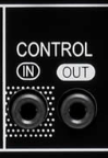 The connectors of this bus are designated as CONTROL IN and CONTROL OUT and are made in the form of mono jack mini jack 3.5mm. Therefore, block connections on the SR bus can be made with conventional two-pin audio cables with mono mini plug 3.5mm plugs (TS-type connector, from Tip-Sleeve). The devices are connected in series, in a daisy chain: the CONTROL OUT output of one component is connected to the CONTROL IN input of another. The contact Tip of the connector carries the SR bus signal itself, but with the Contact contact the case is a bit more complicated. On some components (for example, the M-10X amplifier) here is an honest "ground", and then everything is as it should be: Tip - signal, Sleeve - "earth". But there are components (usually players) that use the sleeve pin of the SR bus connector to transmit a digital audio signal. In this case, the “ground” is taken from the component case or from the “ground” of the analog audio connector. In fact, if the "earths" of the components are connected in some way, then you can forget about the contact of the Sleeve of the SR bus connector.
SR bus control codes are nothing more than demodulated remote control signals. That is, the SR bus is simply a wired repeater of IR-cleared commands. (In IR consoles, modulation of ~ 40 kHz carrier frequency control codes is used to, firstly, reduce the power consumption for transmission and increase the service life of the remote control batteries, and secondly, be able to keep up with signals from other remote controls). When an IR command is received from the remote control, the active SR receiver transmits this command via the SR bus. The command is seen by all devices connected to the bus. Components manufactured by Pioneer Corporation can be equipped with one SR bus connector (input only or output only), or two with both input and output. The input, CONTROL IN , is characterized by the presence of a command interpreter (special chip; for example, in an M-10X amplifier it is a PD5637A chip), which is responsible for decoding and executing commands by the device. However, it should be noted that System Remote is a common bus, and control codes are relayed to both CONTROL OUT outputs and CONTROL IN inputs.
')
In the simplest case, the control codes are two-byte, where the first byte is the device type, and the second byte is the actual command code for execution on this type of device. Below for reference is a list of SR bus device types (first control command byte):
- 0x73 Projectors
- 0xA1 Tape decks (Blu-ray Players)
- 0xA2 CD Players
- 0xA3 DVD Players
- 0xA4 Tuners
- 0xA5 Amplifiers (AV Receivers)
- 0xA8 Laserdisc Players
- 0xAB Video Recorders (DVD Recorders)
- 0xAA Plasma Displays
Devices on the SR bus do not have dedicated addresses, the bus is not addressable. Therefore, for example, if two CD players are connected to the bus, then many commands with a device type of 0xA2 will execute both players simultaneously. There are many command codes, command sets depend on the type of device, year of release and even on the component model. At one of the sites of Pioneer Corporation, in the Custom Install section, you can download device codes and control commands for some specific models via this link .
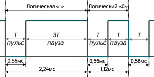
The protocol for transferring information via the System Remote bus is quite simple. Each component on the pin of the bus connectors supports + 5V (TTL logic). To send a frame of information, it is necessary in a certain sequence and with a certain duration to apply the potential of “ground” (0V) to the Tip contact of the SR bus. Pioneer, like many Japanese manufacturers, uses a bit-width codification scheme in IR commands, when a logical zero is encoded with a pulse of 0.56 ms and then a pause of 0.56 ms, and the logical unit is encoded with a pulse of 0.56 ms and then pause 1.68ms.
Figure 1. Coding by bit duration.
The SR bus frame structure for double-byte commands is as follows:
- frame header: a potential of 0V (pulse) is held on the bus for 9ms, then a potential of + 5V for 4.5ms (pause)
- 8 bits: device type code
- 8 bits: bitwise denial of device type code
- 8 bits: command code
- 8 bits: bitwise command code negation
- 1 bit: stop bit
The figure below shows the waveform of the frame of the SR bus 0xA55A38C7, transmitting the power toggle command (command code 0x38) to the amplifier (device type code 0xA5):
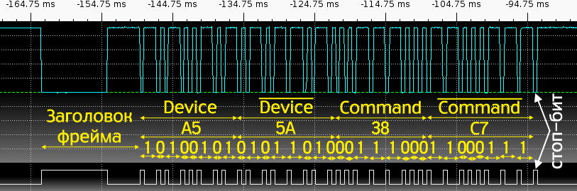
Figure 2. Frame 0xA55A38C7 of the System Remote bus.
Amplifier Pioneer M-10X
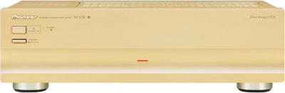 This is a power amplifier, from the controls it has only two buttons: a mechanical Power button and an electronic Standby button. Not much. But, fortunately, it is also equipped with the CONTROL IN input of the System Remote bus and understands three commands:
- power cycle (power toggle) 0xA538
- turn on the power (power on) 0xA558
- turn off the power (power off) 0xA5D8
Connecting the RaspberryPi to the Pioneer System Remote bus
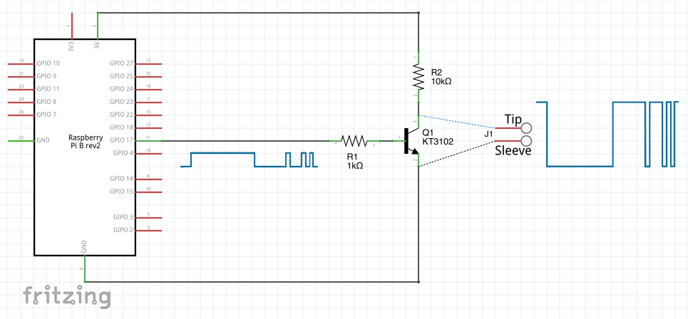
The System Remote bus has TTL logic, the voltage varies from 0V to + 5V. At the GPIO RaspberryPi, the voltage can vary in the range from 0V to + 3.3V, while overvoltage protection for these pins is not provided on the board. Therefore, it is impossible to directly control the SR bus from the GPIO output; you must use a level converter.
The circuit presented here is such a converter. The base of transistor Q1 is connected via resistor R1 to pin P1-11 (GPIO17) RPi, the collector of transistor across resistor R2 connects to pin P1-02 (5V) RPi, and the emitter of transistor connects to pin P1-20 (GND) RPi. By programmatically controlling the output of GPIO17 (base of transistor Q1), on the Tip contact of the terminal block J1 (collector of transistor Q1) we get the signal of the desired level for the control commands of the System Remote bus. Resistor R1 is the base current limiter, and resistor R2 is the collector current limiter of the transistor. When the base of the transistor is 0V (GPIO17 = 0), the transistor is closed and the + 5V potential is held at the emitter; when on the base of the transistor + 3.3V (GPIO17 = 1), the transistor is open and the potential 0V is held at the emitter. Therefore, strictly speaking, this circuit is a signal level inverter. In Figure 2 above, the oscillograms of the working circuit are shown: in the upper graph - the signal at the collector of the transistor (SR bus), in the lower graph - the signal at the base of the transistor (GPIO17 leg; the real range of this signal is from 0V to + 3.3V).
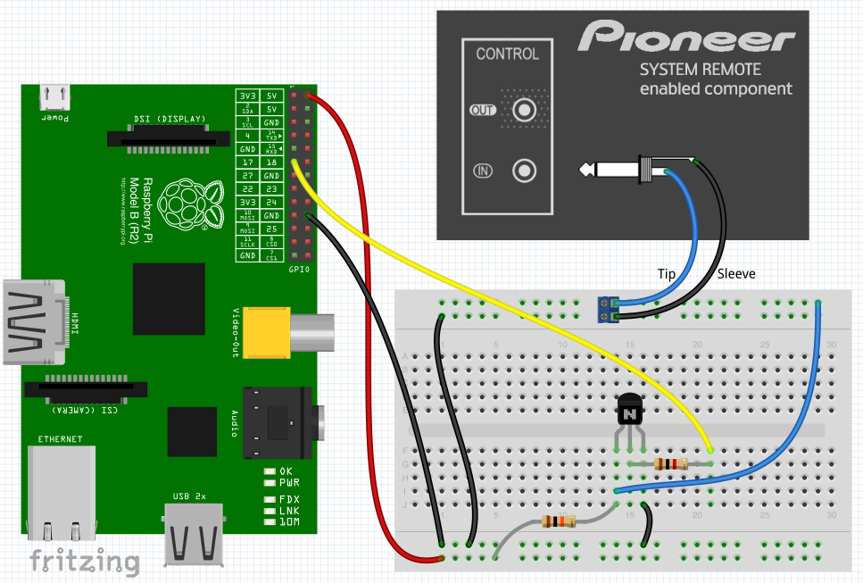
To implement the scheme will need:
- contact breadboard
- KT3102 transistor (Q1)
- 1kOhm resistor (R1)
- 10k ohm resistor (R2)
- terminal strip with 2.54 mm pitch, for installation in a breadboard (J1)
- 3.5mm mini plug mono plug (TS type connector)
- wires
In order not to mess around with soldering the plug, you can take a ready mono cable with a 3.5mm mini plug instead, cut off the connector on one side, and connect the conductors to the J1 terminal box.
Attention! Be very careful with the RaspberryPi five-volt legs (P1-02 and P1-04), do not accidentally short-circuit these contacts with the other legs of the board, as this will damage it.
Pioneer M-10X Amplifier Power Control Software for RaspberryPi
The source code for the Raspbian platform is located at this link . The code contains a nice call (-19) , so the program should be called by the root superuser. To build the program you need to use the command:
gcc -o m10xptgl m10xptgl.c After the build, you need to create two symbolic links with alternative names m10xpon and m10xpoff to the executable file:
ln -s m10xptgl m10xpon ln -s m10xptgl m10xpoff The program generates on the GPIO17 pin a control command frame for the Pioneer M-10X amplifier. The actual action of the program (generated frame) depends on the name under which the program is launched:
- when starting with the name m10xpon , the amplifier turns on (exit from the standby state, frame 0xA55A58A7)
- when starting with the name m10xpoff , the amplifier is turned off (transition to the Standby state, frame 0xA55AD827)
- when starting with the name m10xptgl , the power supply state of the amplifier is switched (power toggle command, frame 0xA55A38C7)
As an optional argument, the program can specify an integer, in which case the frame will be repeated consecutively as many times as specified by the command line argument.
In general, the project is simple, not more difficult than the educational project on LED blinking, only here we “blink” the whole Pioneer amplifier.
Application
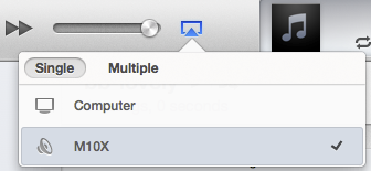
The scheme and program described in the article are convenient to use, for example, with the shairport project, because in this case we get not only the AirPlay function on the old amplifier, but also the automatic on and off of the on demand amplifier.
You can assemble a shairport project from source codes using a sequence of the following commands:
apt-get install avahi-daemon mdns-scan libssl-dev libavahi-client-dev libasound2-dev apt-get install libao4 libao-dev apt-get install pulseaudio libpulse-dev cd /root/src; git clone --depth 1 https://github.com/abrasive/shairport.git shairport cd shairport ./configure make And run like this:
shairport -v --name="M10X" --on-start="/usr/local/sbin/m10xpon 10" --on-stop="/usr/local/sbin/m10xpoff 10" Thanks for attention.
Source: https://habr.com/ru/post/226667/
All Articles