Programming and JTAG debugging of the Atmega16 microcontroller in the C language in the IAR environment, part 2

Introduction
Since The previous article aroused interest, as I promised, this article will cover examples of working with seven-segment indicators, built-in ADCs, and also assembled a digital thermometer software project on the ATmega16 of several examples of working with internal peripheral units microcontroller ATmega16.
Theoretical aspects
For a better understanding of the examples with the ADC, I recommend reading this article . In our case, in all examples, the sampling rate will be 10 Hz, which is equivalent to a sampling period of 100 ms. Since we use a 10-bit ADC built into the Atmega16 microcontroller, then the number of quantization levels will be 1024, which corresponds to a range of values from 0 to 1023 for each polled digital value. The reference voltage in all examples is external and is equal to 5 V. We will not see above the reference voltage at the input, well, below the ground, respectively. This means that when the input voltage of the ADC is 5 V, we get a digital value of 1023, and at 0 V (ground) a digital value of 0. At a voltage of, say, 3.5 V, we get a digital value of (3.5 / 5) = 716. Corrections for nonlinearity, zero offset in the examples we will not do.
An analog sensor TMP36 is used to measure the temperature. This is a low-voltage, precision temperature sensor, the output voltage of which is directly proportional to the temperature on the Celsius scale. We will digitize this voltage using a 10-bit ADC built into the ATmega16 microcontroller.
')
Programming and debugging
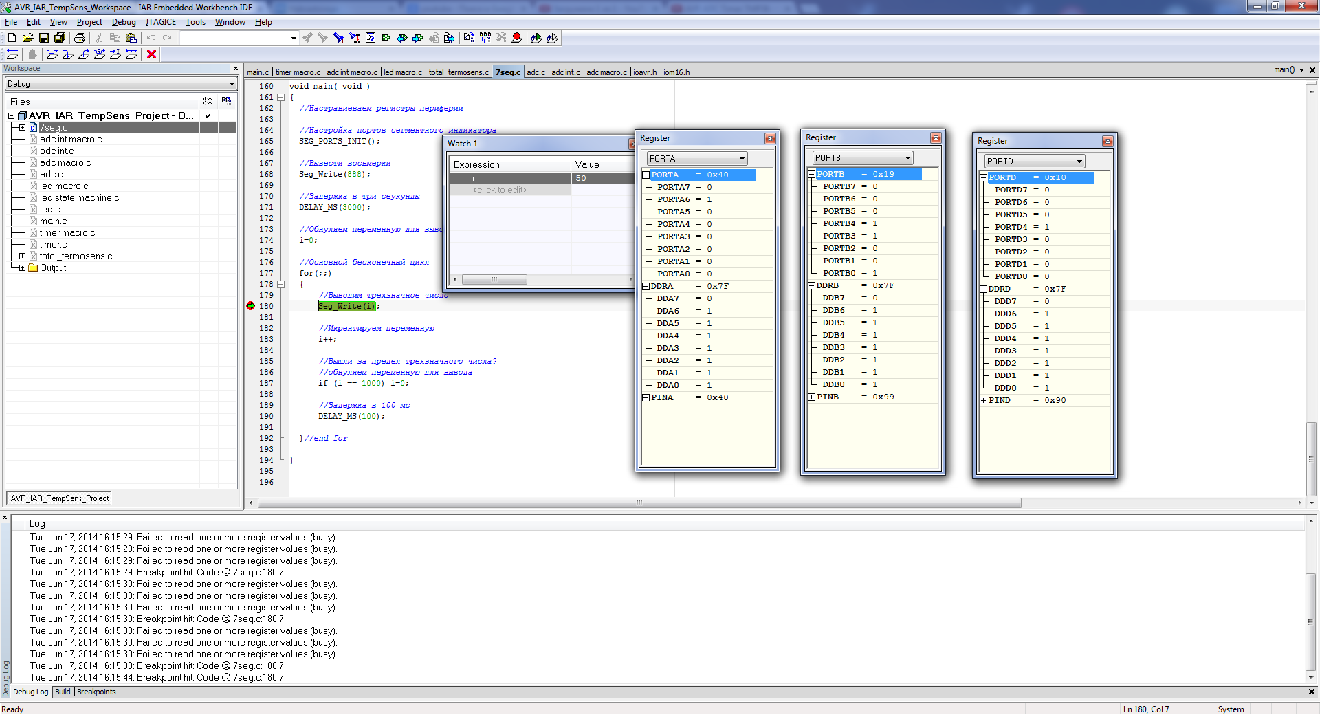
The first example is the output to a three-character seven-segment indicator of numbers in the range from 000 to 999. The indicators are static and are controlled by "0". Those. it can be said that each individual segment is controlled as a separate LED. Each of the three seven-segment indicators is connected to a separate port (ports A, B, D). The connections of the individual segments to the pin numbers, regardless of the port, are the same.
The text of the program of the first example
/* */ #include <ioavr.h> #include <intrinsics.h> #include <ina90.h> /* */ // #define F_CPU 16000000 // #define UCHAR unsigned char #define UINT unsigned int // //0 #define SEG_0 ~(0x3f) //1 #define SEG_1 ~(0x06) //2 #define SEG_2 ~(0x5b) //3 #define SEG_3 ~(0x4F) //4 #define SEG_4 ~(0x66) //5 #define SEG_5 ~(0x6d) //6 #define SEG_6 ~(0x7d) //7 #define SEG_7 ~(0x07) //8 #define SEG_8 ~(0x7F) //9 #define SEG_9 ~(0x6F) //A #define SEG_A ~(0x77) //b #define SEG_b ~(0x7c) //C #define SEG_C ~(0x39) //d #define SEG_d ~(0x5e) //E #define SEG_E ~(0x79) //F #define SEG_F ~(0x71) // #define SEG_MASK (0x7F) // // // #define SEG_1DEC_PORT PORTD // #define SEG_2DEC_PORT PORTB // #define SEG_3DEC_PORT PORTA // #define SEG_1DEC_DDR DDRD // #define SEG_2DEC_DDR DDRB // #define SEG_3DEC_DDR DDRA /* */ // #define DELAY_US(us) __delay_cycles((F_CPU / 1000000) * (us)); // #define DELAY_MS(ms) __delay_cycles((F_CPU / 1000) * (ms)); // #define SEG_PORTS_INIT() ( SEG_3DEC_DDR |= SEG_MASK );\ ( SEG_2DEC_DDR |= SEG_MASK );\ ( SEG_1DEC_DDR |= SEG_MASK ); // #define SEG_PORTS_CLEAR() ( SEG_3DEC_PORT &=~ SEG_MASK );\ ( SEG_2DEC_PORT &=~ SEG_MASK );\ ( SEG_1DEC_PORT &=~ SEG_MASK ); // #define SEG_PORTS_OUT(x,y,z) ( SEG_3DEC_PORT |= ( x & SEG_MASK ) );\ ( SEG_2DEC_PORT |= ( y & SEG_MASK ) );\ ( SEG_1DEC_PORT |= ( z & SEG_MASK ) ); /* */ // const unsigned char numbers[16] = { SEG_0, //0 SEG_1, //1 SEG_2, //2 SEG_3, //3 SEG_4, //4 SEG_5, //5 SEG_6, //6 SEG_7, //7 SEG_8, //8 SEG_9, //9 SEG_A, //A SEG_b, //b SEG_C, //C SEG_d, //d SEG_E, //E SEG_F //F }; // UINT i = 0; /* ** Name: Seg_Write() ** Description: ** ** Parameters: UINT dec3number 0 - 999 ** Returns: none */ void Seg_Write(UINT dec3number) { // UCHAR dec3 = 0 , dec2 = 0 , dec1 = 0; // 4 // dec3number = dec3number % 1000; // dec3 = dec3number / 100; // dec3number = dec3number % 100; // dec2 = dec3number / 10; // dec1 = dec3number % 10; // // SEG_PORTS_CLEAR(); // 3- // // SEG_PORTS_OUT( numbers[dec3], // numbers[dec2], // numbers[dec1] // ); }//end func /* ** Name: main() ** Description: , ** Parameters: none ** Returns: none */ // void main( void ) { // // SEG_PORTS_INIT(); // Seg_Write(888); // DELAY_MS(3000); // i=0; // for(;;) { // Seg_Write(i); // i++; // ? // if (i == 1000) i=0; // 100 DELAY_MS(100); }//end for } To display numbers, hex codes of the form ~ (0x3f) are used, each of which corresponds to a certain decimal digit in the range of 0-9. For each such code, a definition of the form SEG_X is made, where X is the number displayed on the display. These hex-codes are assembled in the numbers [16] array in such a way that the value of the array index corresponds to the output digit. For example, writing to the port of the third element of the numbers [3] array provides output to the indicator of the number 3.
The macro function SEG_PORTS_INIT () provides configuration of the used pins of ports A, B, D to the output. All ports except the eighth are used. The macro function SEG_PORTS_CLEAR () cleans the ports of seven-segment indicators, resetting all the findings to "0". This macro function, together with SEG_PORTS_OUT (x, y, z), which records values to all three ports through a mask conjunction and a disjunction, provides a safe recording of the value to the port without damaging the high bit.
For the convenience of outputting three-digit numbers, the function void Seg_Write (UINT dec3number) is used, where dec3number is the output three-digit number. In the function, each of the three decades of the number is selected by dividing by the integer / and the operation of obtaining the remainder of dividing%. After that, the values of each decade are used as an index of the numbers [decX] array, where decX is one of three decades, and are written to the port using SEG_PORTS_OUT (x, y, z) according to their position in the number.
In the main program loop, the values of the variable i are consistently output, which is incremented and reset when the value exceeds 999. To analyze this condition, use the if statement. The output of the values of the variable i occurs at an interval of 100 ms, which is provided by the DELAY_MS (100) delay macro function already considered in the previous article.
Under debugging, you can see the sequential incrementing of the variable i, as well as which hex codes are converted to the values of this variable using the Seg_Write () function.
The second example is the work with the built-in ADC. An analog signal is connected to its seventh channel, the input of which is connected respectively to the seventh output of port A.
The text of the second example program
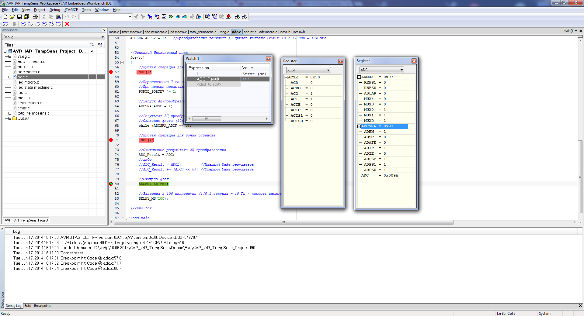
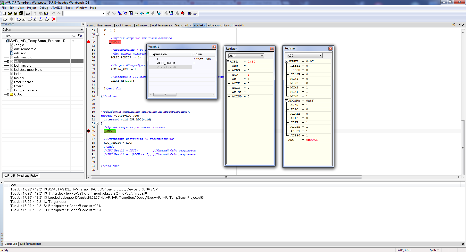
/* */ #include <ioavr.h> #include <intrinsics.h> #include <ina90.h> /* */ // #define F_CPU 16000000 // #define UINT unsigned int /* */ // #define DELAY_US(us) __delay_cycles((F_CPU / 1000000) * (us)); // #define DELAY_MS(ms) __delay_cycles((F_CPU / 1000) * (ms)); /* */ // - UINT ADC_Result = 0; /* */ // void main( void ) { // // // 7- D DDRD_DDD7 = 1; // 7- D "0" PORTD_PORTD7 = 0; // // 7- A DDRA_DDA7 = 0; // PORTA_PORTA7 = 0; ADMUX_MUX0 = 1; // ADMUX_MUX1 = 1; ADMUX_MUX2 = 1; ADCSRA_ADEN = 1; // ADCSRA_ADPS0 = 1; // 16 / 128 = 125 ADCSRA_ADPS1 = 1; // 50-200 ADCSRA_ADPS2 = 1; // 13 125 13 / 125000 = 104 // for(;;) { // _NOP(); // 7- D "0" "1" "1" "0" // PORTD_PORTD7 ^= 1; // - ADCSRA_ADSC = 1; // - ? // (104 ) while (ADCSRA_ADIF == 0); // _NOP(); // - ADC_Result = ADC; // //ADC_Result = ADCL; // //ADC_Result += (ADCH << 8); // // ADCSRA_ADIF=1; // 100 (1/0,1 = 10 - ) DELAY_MS(100); }//end for }//end main In this example, in the function main (), after setting up the LED, already discussed in the previous article, the seventh output of port D is configured for input. For this, the DDD7 bit of the DDRD control register is reset to “0”. After that, the pull-up resistor is forced to turn off on this pin by resetting the PORTA7 bit of the PORTA data register to “0”.
After that, using the record "1" in the MUXx bits of the ADMUX control register, the seventh ADC channel is selected.

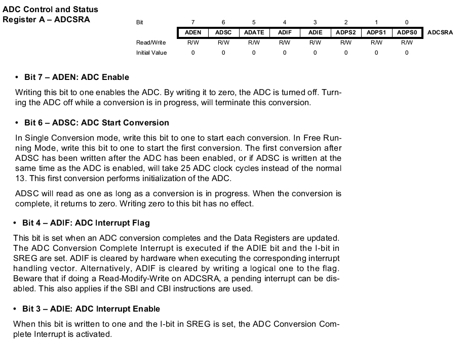
Next, enable the ADC by setting the ADEN bit of the ADCSRA control register.
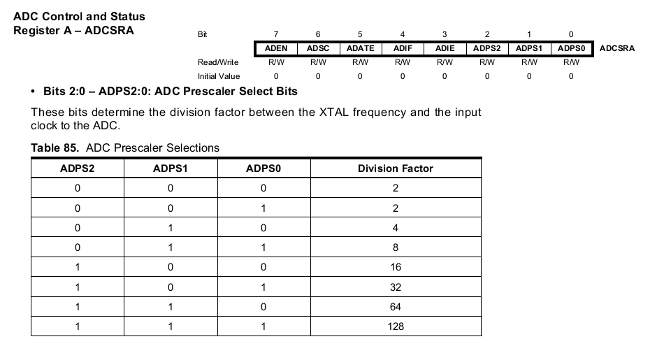
The ADPSx bits of the ADCSRA control register port are set to “1” to ensure the operation of the ADC in the optimal frequency range of 50-200 kHz (as stated in the datasheet). The ADPSx bits provide a prescaler value of 128. A specific frequency value at a clock frequency of 16 MHz will be 16 MHz / 128 = 128 kHz.
After all the necessary settings, cyclic sequential launching and polling of AD conversions are performed using flags. An LED is used to indicate a program event.
The AD conversion is started by setting the ADSC bit of the ADCSRA control register. The readiness of the result is determined by setting the ADIF flag in this control register. At the selected ADC frequency, one conversion will last 104 ms. After setting the ADIF flag, the result of the AD conversion, whose range is 0 - 1023, can be read from the data registers ADCL and ADCH. The result of the AD conversion is written to the ADC_Result variable. Next, you need to clear the ADIF flag with the “1” entry. The polling interval is 100 ms, which is equivalent to a sampling rate of 10 Hz.
Under debugging, you can test the correctness of the ADC setting, as well as evaluate the value in quanta, obtained as a result of the AD conversion.
The third example is also an ADC poll, but with the use of additional macro functions.
Text of the third sample program
/* */ #include <ioavr.h> #include <intrinsics.h> #include <ina90.h> /* */ // #define F_CPU 16000000 // #define UINT unsigned int // // #define LED_DDR DDRD #define LED_PORT PORTD #define LED_PIN DDD7 // #define ADC_IN_DDR DDRA #define ADC_IN_PORT PORTA #define ADC_IN_DDR_PIN DDA7 #define ADC_IN_PORT_PIN PORTA7 // #define ADC0 (0<<MUX2)|(0<<MUX1)|(0<<MUX0) #define ADC1 (0<<MUX2)|(0<<MUX1)|(1<<MUX0) #define ADC2 (0<<MUX2)|(1<<MUX1)|(0<<MUX0) #define ADC3 (0<<MUX2)|(1<<MUX1)|(1<<MUX0) #define ADC4 (1<<MUX2)|(0<<MUX1)|(0<<MUX0) #define ADC5 (1<<MUX2)|(0<<MUX1)|(1<<MUX0) #define ADC6 (1<<MUX2)|(1<<MUX1)|(0<<MUX0) #define ADC7 (1<<MUX2)|(1<<MUX1)|(1<<MUX0) // #define ADC_F_CPU_DIV_2 (0<<ADPS2)|(0<<ADPS1)|(1<<ADPS0) #define ADC_F_CPU_DIV_4 (0<<ADPS2)|(0<<ADPS1)|(1<<ADPS0) #define ADC_F_CPU_DIV_8 (0<<ADPS2)|(1<<ADPS1)|(0<<ADPS0) #define ADC_F_CPU_DIV_16 (0<<ADPS2)|(1<<ADPS1)|(1<<ADPS0) #define ADC_F_CPU_DIV_32 (1<<ADPS2)|(0<<ADPS1)|(0<<ADPS0) #define ADC_F_CPU_DIV_64 (1<<ADPS2)|(1<<ADPS1)|(0<<ADPS0) #define ADC_F_CPU_DIV_128 (1<<ADPS2)|(1<<ADPS1)|(1<<ADPS0) /* */ // #define LED_INIT() ( LED_DDR |= (1<<LED_PIN) ); // #define LED_LOW() ( LED_PORT &=~ (1<<LED_PIN) ); // #define LED_HIGH() ( LED_PORT |= (1<<LED_PIN) ); // #define LED_TOG() ( LED_PORT ^= (1<<LED_PIN) ); // #define ADC_IN_INIT() ( ADC_IN_DDR &= ~(0<<ADC_IN_DDR_PIN) );\ ( ADC_IN_PORT |= (0<<ADC_IN_PORT_PIN) ); // #define ADC_SET_CHAN(x) ( ADMUX |= x ); // #define ADC_ON() ( ADCSRA |= (1<<ADEN) ); // #define ADC_OFF() ( ADCSRA &=~ (1<<ADEN) ); // #define ADC_SET_CLK_DIV(x) ( ADCSRA |= x ); // - #define ADC_START_CONV() ( ADCSRA |= (1<<ADSC) ); // - #define ADC_RES_READY() ( ADCSRA & (1<<ADIF) ) // - #define ADC_FLAG_CLEAR() ( ADCSRA |= (1<<ADIF) ); // #define DELAY_US(us) __delay_cycles((F_CPU / 1000000) * (us)); // #define DELAY_MS(ms) __delay_cycles((F_CPU / 1000) * (ms)); /* */ // - UINT ADC_Result = 0; /* */ // void main( void ) { // // LED_INIT(); // LED_LOW(); // // ADC_IN_INIT(); // ADC_SET_CHAN(ADC7); ADC_ON(); // // 16 / 128 = 125 ADC_SET_CLK_DIV(ADC_F_CPU_DIV_128); // 50-200 // 13 125 13 / 125000 = 104 // for(;;) { // _NOP(); // LED_TOG(); // - ADC_START_CONV(); // - ? // (104 ) while(!ADC_RES_READY()); // _NOP(); // - ADC_Result = ADC; // //ADC_Result = ADCL; // //ADC_Result += (ADCH << 8); // // ADC_FLAG_CLEAR(); // 100 (1/0,1 = 10 - ) DELAY_MS(100); }//end for }//end main Initialization of the input of the seventh channel of the ADC is carried out using the macro function ADC_IN_INIT (). The definitions of ADC_IN_DDR, ADC_IN_PORT, ADC_IN_DDR_PIN, ADC_IN_PORT_PIN provide an easy possible change in the output and, accordingly, the ADC channel.
The bits in the ADMUX channel selection control register, when tuned, are implemented using the macro function ADC_SET_CHAN (ADCx), whose argument ADCx determines the channel number, where x is selected in the range from 0 to 7. Each ADCx definition is a collection of MUXx control bit values, the value of which “0” and “1” correspond to the selected channel number x.
The ADC is turned on by the ADC_ON () macro function. The frequency divider is selected using the macro function ADC_SET_CLK_DIV (ADC_F_CPU_DIV_x), where the argument is selected from a number of definitions ADC_F_CPU_DIV_x, in which x is taken from the set 2,4,8,16,32,64,128 and corresponds to the selected microcontroller clock prefacitor.
The AD conversion is executed by the ADC_START_CONV () macro function. The readiness of the AD conversion is determined by the macro function ADC_RES_READY (). Clearing the flag with ADC_FLAG_CLEAR ().
The fourth example is an ADC poll using an interrupt mechanism to capture the readiness event instead of flags.
The text of the program of the fourth example
/* */ #include <ioavr.h> #include <intrinsics.h> #include <ina90.h> /* */ // #define F_CPU 16000000 // #define UINT unsigned int /* */ // #define DELAY_US(us) __delay_cycles((F_CPU / 1000000) * (us)); // #define DELAY_MS(ms) __delay_cycles((F_CPU / 1000) * (ms)); /* */ // - UINT ADC_Result = 0; /* */ // void main( void ) { // // // 7- D DDRD_DDD7 = 1; // 7- D "0" PORTD_PORTD7 = 0; // // 7- A DDRA_DDA7 = 0; // PORTA_PORTA7 = 1; ADMUX_MUX0 = 1; // ADMUX_MUX1 = 1; ADMUX_MUX2 = 1; ADCSRA_ADEN = 1; // ADCSRA_ADPS0 = 1; // 16 / 128 = 125 ADCSRA_ADPS1 = 1; // 50-200 ADCSRA_ADPS2 = 1; // 13 125 13 / 125000 = 104 ADCSRA_ADIE = 1; // // _SEI(); // for(;;) { // _NOP(); // 7- D "0" "1" "1" "0" // PORTD_PORTD7 ^= 1; // - ADCSRA_ADSC = 1; // 100 (1/0,1 = 10 - ) DELAY_MS(100); }//end for }//end main /* -*/ #pragma vector=ADC_vect __interrupt void ISR_ADC(void) { // _NOP(); // - ADC_Result = ADC; // //ADC_Result = ADCL; // //ADC_Result += (ADCH << 8); // }//end func In order to enable an interrupt on readiness of the AD conversion result, you must set the ADIE bit in the control register ADCSRA. Then we do the global resolution of all masked interrupts with the _SEI () macro function.
The logic of the program is the system with a super-cycle already described in the first article, where the quasi-parallel operation of the main loop and interrupt handler is provided. In the main cycle, the AC conversion starts with a period of 100 ms. After an interval of approximately 104 μs, the main loop is interrupted to process an interrupt on the readiness event of the AD-conversion. Interrupt processing is performed using the ISR_ADC () handler function, which is called upon this event. The result of the AD conversion is copied from the data registers ADCL and ADCH in the body of the handler function.
Under debugging, you can test the correctness of the interrupt subsystem for the peripheral ADC module.
The fifth example is a symbiosis of the third and fourth example. This is an ADC poll with the help of interrupts using macro functions.
The text of the program of the fifth example
/* */ #include <ioavr.h> #include <intrinsics.h> #include <ina90.h> /* */ // #define F_CPU 16000000 // #define UINT unsigned int // // #define LED_DDR DDRD #define LED_PORT PORTD #define LED_PIN DDD7 // #define ADC_IN_DDR DDRA #define ADC_IN_PORT PORTA #define ADC_IN_DDR_PIN DDA7 #define ADC_IN_PORT_PIN PORTA7 // #define ADC0 (0<<MUX2)|(0<<MUX1)|(0<<MUX0) #define ADC1 (0<<MUX2)|(0<<MUX1)|(1<<MUX0) #define ADC2 (0<<MUX2)|(1<<MUX1)|(0<<MUX0) #define ADC3 (0<<MUX2)|(1<<MUX1)|(1<<MUX0) #define ADC4 (1<<MUX2)|(0<<MUX1)|(0<<MUX0) #define ADC5 (1<<MUX2)|(0<<MUX1)|(1<<MUX0) #define ADC6 (1<<MUX2)|(1<<MUX1)|(0<<MUX0) #define ADC7 (1<<MUX2)|(1<<MUX1)|(1<<MUX0) // #define ADC_F_CPU_DIV_2 (0<<ADPS2)|(0<<ADPS1)|(1<<ADPS0) #define ADC_F_CPU_DIV_4 (0<<ADPS2)|(0<<ADPS1)|(1<<ADPS0) #define ADC_F_CPU_DIV_8 (0<<ADPS2)|(1<<ADPS1)|(0<<ADPS0) #define ADC_F_CPU_DIV_16 (0<<ADPS2)|(1<<ADPS1)|(1<<ADPS0) #define ADC_F_CPU_DIV_32 (1<<ADPS2)|(0<<ADPS1)|(0<<ADPS0) #define ADC_F_CPU_DIV_64 (1<<ADPS2)|(1<<ADPS1)|(0<<ADPS0) #define ADC_F_CPU_DIV_128 (1<<ADPS2)|(1<<ADPS1)|(1<<ADPS0) /* */ // #define LED_INIT() ( LED_DDR |= (1<<LED_PIN) ); // #define LED_LOW() ( LED_PORT &=~ (1<<LED_PIN) ); // #define LED_HIGH() ( LED_PORT |= (1<<LED_PIN) ); // #define LED_TOG() ( LED_PORT ^= (1<<LED_PIN) ); // #define ADC_IN_INIT() ( ADC_IN_DDR &= ~(0<<ADC_IN_DDR_PIN) );\ ( ADC_IN_PORT |= (0<<ADC_IN_PORT_PIN) ); // #define ADC_SET_CHAN(x) ( ADMUX |= x ); // #define ADC_ON() ( ADCSRA |= (1<<ADEN) ); // #define ADC_OFF() ( ADCSRA &=~ (1<<ADEN) ); // #define ADC_SET_CLK_DIV(x) ( ADCSRA |= x ); // - #define ADC_START_CONV() ( ADCSRA |= (1<<ADSC) ); // #define ADC_INT_ON() ( ADCSRA |= (1<<ADIE) ); // #define DELAY_US(us) __delay_cycles((F_CPU / 1000000) * (us)); // #define DELAY_MS(ms) __delay_cycles((F_CPU / 1000) * (ms)); /* */ // - UINT ADC_Result = 0; /* */ // void main( void ) { // // LED_INIT(); // LED_LOW(); // // ADC_IN_INIT(); // ADC_SET_CHAN(ADC7); ADC_ON(); // // 16 / 128 = 125 ADC_SET_CLK_DIV(ADC_F_CPU_DIV_128); // 50-200 // 13 125 13 / 125000 = 104 ADC_INT_ON(); // // _SEI(); // for(;;) { // _NOP(); // LED_TOG(); // - ADC_START_CONV(); // 100 (1/0,1 = 10 - ) DELAY_MS(100); }//end for }//end main /* -*/ #pragma vector=ADC_vect __interrupt void ISR_ADC(void) { // _NOP(); // - ADC_Result = ADC; // //ADC_Result = ADCL; // //ADC_Result += (ADCH << 8); // }//end func To enable interrupts, use the macro function ADC_INT_ON ().
Having considered all the necessary examples, let's move on to the whole project of a digital thermometer, made on the basis of the already considered examples of working with the internal microcontroller peripheral blocks.
Text of the digital thermometer program
/* */ #include <ioavr.h> #include <intrinsics.h> #include <ina90.h> #include <stdbool.h> /* */ // #define F_CPU 16000000 // #define UCHAR unsigned char #define UINT unsigned int #define FLOAT_TYPE float // // #define LED_DDR DDRD #define LED_PORT PORTD #define LED_PIN DDD7 // #define F_CPU_DIV_1 (0<<CS02)|(0<<CS01)|(1<<CS00) #define F_CPU_DIV_8 (0<<CS02)|(1<<CS01)|(0<<CS00) #define F_CPU_DIV_64 (0<<CS02)|(1<<CS01)|(1<<CS00) #define F_CPU_DIV_256 (1<<CS02)|(0<<CS01)|(0<<CS00) #define F_CPU_DIV_1024 (1<<CS02)|(0<<CS01)|(1<<CS00) // #define TCNT0_VALUE 99 // #define T0_TICK_CNT_LIMIT 10 // #define ADC_IN_DDR DDRA #define ADC_IN_PORT PORTA #define ADC_IN_DDR_PIN DDA7 #define ADC_IN_PORT_PIN PORTA7 // #define ADC0 (0<<MUX2)|(0<<MUX1)|(0<<MUX0) #define ADC1 (0<<MUX2)|(0<<MUX1)|(1<<MUX0) #define ADC2 (0<<MUX2)|(1<<MUX1)|(0<<MUX0) #define ADC3 (0<<MUX2)|(1<<MUX1)|(1<<MUX0) #define ADC4 (1<<MUX2)|(0<<MUX1)|(0<<MUX0) #define ADC5 (1<<MUX2)|(0<<MUX1)|(1<<MUX0) #define ADC6 (1<<MUX2)|(1<<MUX1)|(0<<MUX0) #define ADC7 (1<<MUX2)|(1<<MUX1)|(1<<MUX0) // #define ADC_F_CPU_DIV_2 (0<<ADPS2)|(0<<ADPS1)|(1<<ADPS0) #define ADC_F_CPU_DIV_4 (0<<ADPS2)|(0<<ADPS1)|(1<<ADPS0) #define ADC_F_CPU_DIV_8 (0<<ADPS2)|(1<<ADPS1)|(0<<ADPS0) #define ADC_F_CPU_DIV_16 (0<<ADPS2)|(1<<ADPS1)|(1<<ADPS0) #define ADC_F_CPU_DIV_32 (1<<ADPS2)|(0<<ADPS1)|(0<<ADPS0) #define ADC_F_CPU_DIV_64 (1<<ADPS2)|(1<<ADPS1)|(0<<ADPS0) #define ADC_F_CPU_DIV_128 (1<<ADPS2)|(1<<ADPS1)|(1<<ADPS0) // //0 #define SEG_0 ~(0x3f) //1 #define SEG_1 ~(0x06) //2 #define SEG_2 ~(0x5b) //3 #define SEG_3 ~(0x4F) //4 #define SEG_4 ~(0x66) //5 #define SEG_5 ~(0x6d) //6 #define SEG_6 ~(0x7d) //7 #define SEG_7 ~(0x07) //8 #define SEG_8 ~(0x7F) //9 #define SEG_9 ~(0x6F) //A #define SEG_A ~(0x77) //b #define SEG_b ~(0x7c) //C #define SEG_C ~(0x39) //d #define SEG_d ~(0x5e) //E #define SEG_E ~(0x79) //F #define SEG_F ~(0x71) // #define SEG_GRAD ~(0x63) // #define SEG_MASK (0x7F) // // // #define SEG_1DEC_PORT PORTD // #define SEG_2DEC_PORT PORTB // #define SEG_3DEC_PORT PORTA // #define SEG_1DEC_DDR DDRD // #define SEG_2DEC_DDR DDRB // #define SEG_3DEC_DDR DDRA /* */ // #define LED_INIT() ( LED_DDR |= (1<<LED_PIN) ); // #define LED_LOW() ( LED_PORT &=~ (1<<LED_PIN) ); // #define LED_HIGH() ( LED_PORT |= (1<<LED_PIN) ); // #define LED_TOG() ( LED_PORT ^= (1<<LED_PIN) ); // #define TIMER0_SET_CLK_DIV(x) ( TCCR0 |= x ); // #define TIMER0_SET_CNT(x) ( TCNT0 = x ); // #define TIMER0_OVF_INT_ON() ( TIMSK|=(1<<TOIE0) ); // #define ADC_IN_INIT() ( ADC_IN_DDR &= ~(0<<ADC_IN_DDR_PIN) );\ ( ADC_IN_PORT &= ~(0<<ADC_IN_PORT_PIN) ); // #define ADC_SET_CHAN(x) ( ADMUX |= x ); // #define ADC_ON() ( ADCSRA |= (1<<ADEN) ); // #define ADC_OFF() ( ADCSRA &=~ (1<<ADEN) ); // #define ADC_SET_CLK_DIV(x) ( ADCSRA |= x ); // - #define ADC_START_CONV() ( ADCSRA |= (1<<ADSC) ); // #define ADC_INT_ON() ( ADCSRA |= (1<<ADIE) ); // #define SEG_PORTS_INIT() ( SEG_3DEC_DDR |= SEG_MASK );\ ( SEG_2DEC_DDR |= SEG_MASK );\ ( SEG_1DEC_DDR |= SEG_MASK ); // #define SEG_PORTS_CLEAR() ( SEG_3DEC_PORT &=~ SEG_MASK );\ ( SEG_2DEC_PORT &=~ SEG_MASK );\ ( SEG_1DEC_PORT &=~ SEG_MASK ); // #define SEG_PORTS_OUT(x,y,z) ( SEG_3DEC_PORT |= ( x & SEG_MASK ) );\ ( SEG_2DEC_PORT |= ( y & SEG_MASK ) );\ ( SEG_1DEC_PORT |= ( z & SEG_MASK ) ); // #define DELAY_US(us) __delay_cycles((F_CPU / 1000000) * (us)); // #define DELAY_MS(ms) __delay_cycles((F_CPU / 1000) * (ms)); /* */ // T0 UINT T0_tick_cnt=0; // const unsigned char numbers[16] = { SEG_0, //0 SEG_1, //1 SEG_2, //2 SEG_3, //3 SEG_4, //4 SEG_5, //5 SEG_6, //6 SEG_7, //7 SEG_8, //8 SEG_9, //9 SEG_A, //A SEG_b, //b SEG_C, //C SEG_d, //d SEG_E, //E SEG_F //F }; // FLOAT_TYPE T = 0; // - UINT ADC_Result = 0; // - - UINT ADC_res_cnt = 0; // UINT Sum = 0; // - bool ADCReadyFlag = false; /* ** Name: Seg_Write() ** Description: ** ** Parameters: UINT T - 0 - 99 C ** Returns: none */ void Seg_Write(UINT T) { // UINT dec2 = 0 , dec1 = 0; // T = T % 100; // dec2 = T / 10; // dec1 = T % 10; // // SEG_PORTS_CLEAR(); // 3- // // SEG_PORTS_OUT( numbers[dec2], // numbers[dec1], // SEG_GRAD // ); }//end func /* ** Name: main() ** Description: , ** Parameters: none ** Returns: none */ // void main( void ) { // // SEG_PORTS_INIT(); // LED_INIT(); // LED_LOW(); // ( Normal) TIMER0_SET_CLK_DIV(F_CPU_DIV_1024);// 16 000 000 // 16 000 000 / 1024 = 15 625 // 1 / 15 625 = 0,000064 =64 TIMER0_SET_CNT(TCNT0_VALUE); // 156 * 0,000064 c = 0,009984 c (10 ) // 255-156 = 99 TIMER0_OVF_INT_ON(); // // // ADC_IN_INIT(); // ADC_SET_CHAN(ADC7); ADC_ON(); // // 16 / 128 = 125 ADC_SET_CLK_DIV(ADC_F_CPU_DIV_128); // 50-200 // 13 125 13 / 125000 = 104 ADC_INT_ON(); // // T=0; // Sum = 0; // _SEI(); // for(;;) { // _NOP(); // - // if(ADCReadyFlag) { // _NOP(); // ADCReadyFlag = false; // LED_TOG(); // //- Sum += ADC_Result; // //- ADC_res_cnt++; // -? if ( ADC_res_cnt == 8 ) { // _NOP(); // ADC_res_cnt = 0; // ADC_Result = Sum / 8; // Sum = 0; // T = ADC_Result*(5.0/1023); // T = ((T-0.75)*100)+25; // // Seg_Write((UINT)T); }//end if }//end if }//end for }//end main /* T0 */ #pragma vector=TIMER0_OVF_vect __interrupt void ISR_TickTimer(void) { // _NOP(); // T0 T0_tick_cnt++; // 100 if (T0_tick_cnt >= T0_TICK_CNT_LIMIT) { // _NOP(); // T0 T0_tick_cnt=0; // // - ADC_START_CONV(); }//end for // // TIMER0_SET_CNT(TCNT0_VALUE); }//end func /* -*/ #pragma vector=ADC_vect __interrupt void ISR_ADC(void) { // _NOP(); // - ADC_Result = ADC; // //ADC_Result = ADCL; // //ADC_Result += (ADCH << 8); // // - ADCReadyFlag = true; }//end func In the setting of the peripheral registers, the settings of the LED, the hardware timer, and the A / D converter already discussed in the examples of the macro function are used.
The logic of the program is focused on the quasi-parallel operation of the main loop and two interrupt handlers for the tick hardware timer and the ADC. In the tick timer interrupt handler, a 100 ms interval passing event is triggered by an AD conversion using the macro function ADC_START_CONV (). After an interval of approximately equal to 104 μs, an interrupt is triggered by the readiness of the result of the AD conversion. In the body of the ISR_ADC () handler, the result of the AD conversion is written to the ADC_Result variable and the readiness flag ADCReadyFlag of the bool type is set (for using this type, the library stdbool.h was previously included with the #include directive).
The event of setting this flag is fixed in the main loop by the if operator. After that, the flag is reset and the result of the AD-conversion ADC_Result is added to the variable Sum until eight results of the AD-conversion are summed. When eight results are obtained and summed, the sum in the variable Sum is divided by eight. Thus, a simple version of digital filtering is implemented and the low-order bit noise is reduced due to the noisy USB power supply in addition to external filtering circuits.
The filtered result is written to the ADC_Result variable, and the Sum variable is reset. Further, the obtained filtered result in quanta is converted to volts using simple arithmetic operations. Sincethe reference voltage is 5 V, and the maximum value in quanta corresponding to it is 1023, then to translate our value in volts in quanta, it is enough to divide it by 1023 and multiply by 5. We will keep the resulting fractional value in real type. Further, having a datasheet on TMP36 on hand and knowing that at 25 degrees the output should be 750 mV and that each degree up or down corresponds to 10 mV, it is easy to convert the fractional result in volts to degrees using the following expression T = ((( -0.75) * 100) +25. Next, the temperature value in degrees is displayed on seven-segment indicators using the void Seg_Write (UINT T) function, which, unlike the first example, displays two-digit numbers with the degree symbol. The logic of the selection of decades of the number displayed on the display is the same.
Under debugging, you can trace all the described logic of the program, as well as the correctness of the calculation of both the values of intermediate variables and the final result.

Conclusion
All examples in the form of the IAR project can be downloaded here .
If this post is of interest, then in the next part we will look at new examples on a new, specially designed board.
Source: https://habr.com/ru/post/226539/
All Articles