Shadow rendering using Parallel-Split Shadow Mapping
 Hi, Habr! My previous post on graphics programming was well received by the community, and I ventured another one. Today I will talk about the Parallel-Split Shadow Mapping (PSSM) shadow rendering algorithm, which I first encountered when there was a working need to display shadows at a great distance from the player. Then I was limited to the Direct3D 10 feature set, now I implemented the algorithm on Direct3D 11 and OpenGL 4.3. The PSSM algorithm is described in more detail in GPU Gems 3, both from a mathematical point of view, and from the point of view of implementation on Direct3D 9 and 10. For details, I ask for cat.
A demo can be found here . The project is called Demo_PSSM. You will need Visual Studio 2012/2013 and CMake to build.
Shadow mapping
The original shadow mapping algorithm was invented a long time ago. The principle of its operation is as follows:
- Draw a scene into the texture (shadow map) from the position of the light source. It is important to note here that for different types of light sources everything happens a little differently.
Directional sources of light (such as, in a certain approximation, sunlight can be attributed) do not have a position in space, but in order to form a shadow map this position has to be chosen. Usually it is tied to the observer's position, so that objects that are directly in the field of view of the observer fall into the shadow map. When rendering using orthographic projection .
Projection sources of light (lamps with an opaque shade, spotlights) have a certain position in space and limit the propagation of light in certain directions. When rendering a shadow map in this case, the usual perspective projection matrix is used .
Omnidirectional light sources (incandescent lamps, for example), although they have a certain position in space, propagate light in all directions. In order to correctly construct the shadows from such a light source, it is necessary to use cubic textures (cube maps), which, as a rule, means drawing a scene into a shadow map 6 times. Not every game can afford dynamic shadows from such light sources, and not every game needs it. If you are interested in the principles of this approach, there is an old article on this topic.
In addition, there is a subclass of shadow mapping algorithms ( LiSPSM , TSM , PSM , etc.) that use non-standard projection view matrices to improve the quality of shadows and eliminate the drawbacks of the original approach.
Whatever way the shadow map is formed, it invariably contains the distance from the light source to the nearest visible (from the position of the light source) point or function from this distance in more complex varieties of the algorithm. - We draw a scene from the main camera. In order to understand whether a point of any object is in the shadow, it is enough to translate the coordinates of this point into the space of a shadow map and make a comparison. The space of the shadow map is determined by the projection view matrix that was used in the formation of this map. Transferring the coordinates of the object point to this space and converting the coordinates from the range [-1; -1] to [0; 1] , we obtain the texture coordinates. If the obtained coordinates turned out to be outside the range [0; 1] , then this point did not fall into the shadow map, and it can be considered unshadowed. Making a sample of the shadow map on the received texture coordinates, we get the distance between the light source and the nearest point of an object. If we compare this distance with the distance between the current point and the light source, then the point is in the shadow if the value in the shadow map is smaller. It is quite simple from a logical point of view, if the value from the shadow map is smaller, it means that at this point there is some object that is closer to the light source, and we are in its shadow.
Shadow mapping is by far the most common algorithm for rendering dynamic shadows. The implementation of one or another modification of the algorithm can be found in almost any graphics engine. The main advantage of this algorithm is that it ensures the rapid formation of shadows from arbitrarily geometrically complex objects. However, the existence of a wide range of variations of the algorithm is largely due to its shortcomings, which can lead to very unpleasant graphic artifacts. PPSM-specific problems and ways to overcome them will be discussed below.
Parallel-Split Shadow Mapping
Consider the following task: it is necessary to draw dynamic shadows from objects that are at a considerable distance from the player without prejudice to the shadows from closely located objects. We confine ourselves to directed sunlight.
A task of this kind can be especially relevant in outdoor games, where in some situations a player can see the landscape hundreds of meters in front of him. In this case, the further we want to see the shadow, the more space should fall into the shadow map. In order to maintain the proper resolution of objects in the shadow map, we are forced to increase the resolution of the card itself, which first leads to a decrease in performance, then we rest on the limit on the maximum size of the target target. As a result, balancing between the performance and the quality of the shadow, we get the shadow with a well-marked aliasing effect, which is poorly masked even by blurring. It is clear that such a decision cannot satisfy us.
To solve this problem, we can come up with a projection matrix so that the objects close to the player receive in the shadow map an area larger than objects that are far away. This is the basic idea of the Perspective Shadow Mapping (PSM) algorithm and a number of other algorithms. The main advantage of this approach is the fact that we practically did not change the process of rendering the scene, only the method of calculating the projection view matrix has changed. This approach can be easily integrated into an existing game or engine without the need for major modifications of the latter. The main disadvantage of this type of approach is the boundary conditions. Imagine the situation that we draw the shadows from the sun at sunset. When the sun approaches the horizon, the objects in the shadow map begin to overlap each other. In this case, an atypical projection matrix can exacerbate the situation. In other words, PSM class algorithms work well in certain situations, for example, when the game draws shadows from the “fixed Sun” close to the zenith.
A fundamentally different approach is proposed in the PSSM algorithm. For some, this algorithm may be known as Cascaded Shadow Mapping (CSM). Formally, these are different algorithms, I would even say that PSSM is a special case of CSM. In this algorithm, it is proposed to divide the frustum of the main camera into segments. In the case of PSSM, with boundaries parallel to the near and far cut-off planes, in the case of CSM, the type of separation is not strictly regulated. For each segment ( split in the terminology of the algorithm) its own shadow card is built. An example of separation is shown in the figure below.
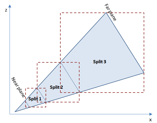
In the figure you can see the division of the pyramid of visibility into 3 segments. Each of the segments is highlighted by a bounding box (in three-dimensional space there will be a parallelepiped, a bounding box). For each of these limited parts of the space will be built its own shadow map. The attentive reader will notice that here I used bounding box parallelepipeds. You can also use unaligned ones, this will add additional complexity to the object clipping algorithm and will slightly change the way the matrix of the view is formed from the position of the light source. As the pyramid of visibility expands, the area of the segments closer to the camera can be significantly less than the area of the farthest. With the same resolution of shadow maps, this means a higher resolution for the shadow of closely located objects. In the above-mentioned article in GPU Gems 3 , the following scheme was proposed for calculating the distances of the partition of the pyramid of visibility:
')

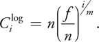
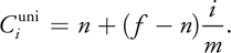
where i is the partitioning index, m is the number of partitions, n is the distance to the near cut plane, f is the distance to the far cut plane, λ is the coefficient determining the interpolation between the logarithmic and uniform split scale.
Common in implementation
The PSSM algorithm in the implementation on Direct3D 11 and OpenGL has a lot in common. To implement the algorithm it is necessary to prepare the following:
- Several shadow maps (by the number of splits). At first glance, it seems that in order to obtain several shadow maps, it is necessary to draw objects several times. Actually, it is not necessary to do this explicitly, we will use the mechanism of hardware instansing. To do this, we need a so-called array of textures for rendering and a simple geometric shader.
- The mechanism of clipping objects. The objects of the game world can be of different geometric shapes and have a different position in space. Extended objects can be seen in several shadow maps, small objects - only in one. The object may be directly on the border of neighboring segments and must be drawn in at least 2 shadow maps. Thus, a mechanism is needed to determine which subset of the shadow maps falls on an object.
- A mechanism for determining the optimal number of partitions. Rendering shadow maps for each segment per frame can be a waste of computational resources. In many situations, the player sees in front of him only a small portion of the game world (for example, he looks at his feet, or his gaze rested on the wall in front of him). It is clear that this greatly depends on the type of review in the game, but it would be nice to have such optimization.
As a result, we obtain the following algorithm for generating projection view matrices for rendering shadow maps:
- Calculate the distances to divide the visibility pyramid for the worst case. The worst case here is we see the shadows to the far clipping plane of the camera.Code
void calculateMaxSplitDistances() { float nearPlane = m_camera.getInternalCamera().GetNearPlane(); float farPlane = m_camera.getInternalCamera().GetFarPlane(); for (int i = 1; i < m_splitCount; i++) { float f = (float)i / (float)m_splitCount; float l = nearPlane * pow(farPlane / nearPlane, f); float u = nearPlane + (farPlane - nearPlane) * f; m_maxSplitDistances[i - 1] = l * m_splitLambda + u * (1.0f - m_splitLambda); } m_farPlane = farPlane + m_splitShift; } - Determine the distance between the camera and the most distant visible point of the object casting a shadow. It is important to note here that objects can cast and not cast shadows. For example, a flat-hilly landscape can be made without casting shadows; in this case, the lighting algorithm can be responsible for shading. Only shadow objects will be drawn into the shadow map.Code
float calculateFurthestPointInCamera(const matrix44& cameraView) { bbox3 scenebox; scenebox.begin_extend(); for (size_t i = 0; i < m_entitiesData.size(); i++) { if (m_entitiesData[i].isShadowCaster) { bbox3 b = m_entitiesData[i].geometry.lock()->getBoundingBox(); b.transform(m_entitiesData[i].model); scenebox.extend(b); } } scenebox.end_extend(); float maxZ = m_camera.getInternalCamera().GetNearPlane(); for (int i = 0; i < 8; i++) { vector3 corner = scenebox.corner_point(i); float z = -cameraView.transform_coord(corner).z; if (z > maxZ) maxZ = z; } return std::min(maxZ, m_farPlane); } - On the basis of the values obtained at steps 1 and 2, we determine the number of segments that we really need and the separation distances for them.Code
void calculateSplitDistances() { // calculate how many shadow maps do we really need m_currentSplitCount = 1; if (!m_maxSplitDistances.empty()) { for (size_t i = 0; i < m_maxSplitDistances.size(); i++) { float d = m_maxSplitDistances[i] - m_splitShift; if (m_furthestPointInCamera >= d) m_currentSplitCount++; } } float nearPlane = m_camera.getInternalCamera().GetNearPlane(); for (int i = 0; i < m_currentSplitCount; i++) { float f = (float)i / (float)m_currentSplitCount; float l = nearPlane * pow(m_furthestPointInCamera / nearPlane, f); float u = nearPlane + (m_furthestPointInCamera - nearPlane) * f; m_splitDistances[i] = l * m_splitLambda + u * (1.0f - m_splitLambda); } m_splitDistances[0] = nearPlane; m_splitDistances[m_currentSplitCount] = m_furthestPointInCamera; } - For each segment (the boundaries of the segment are determined by the near and far distances) we calculate the bounding box.Code
bbox3 calculateFrustumBox(float nearPlane, float farPlane) { vector3 eye = m_camera.getPosition(); vector3 vZ = m_camera.getOrientation().z_direction(); vector3 vX = m_camera.getOrientation().x_direction(); vector3 vY = m_camera.getOrientation().y_direction(); float fov = n_deg2rad(m_camera.getInternalCamera().GetAngleOfView()); float aspect = m_camera.getInternalCamera().GetAspectRatio(); float nearPlaneHeight = n_tan(fov * 0.5f) * nearPlane; float nearPlaneWidth = nearPlaneHeight * aspect; float farPlaneHeight = n_tan(fov * 0.5f) * farPlane; float farPlaneWidth = farPlaneHeight * aspect; vector3 nearPlaneCenter = eye + vZ * nearPlane; vector3 farPlaneCenter = eye + vZ * farPlane; bbox3 box; box.begin_extend(); box.extend(vector3(nearPlaneCenter - vX * nearPlaneWidth - vY * nearPlaneHeight)); box.extend(vector3(nearPlaneCenter - vX * nearPlaneWidth + vY * nearPlaneHeight)); box.extend(vector3(nearPlaneCenter + vX * nearPlaneWidth + vY * nearPlaneHeight)); box.extend(vector3(nearPlaneCenter + vX * nearPlaneWidth - vY * nearPlaneHeight)); box.extend(vector3(farPlaneCenter - vX * farPlaneWidth - vY * farPlaneHeight)); box.extend(vector3(farPlaneCenter - vX * farPlaneWidth + vY * farPlaneHeight)); box.extend(vector3(farPlaneCenter + vX * farPlaneWidth + vY * farPlaneHeight)); box.extend(vector3(farPlaneCenter + vX * farPlaneWidth - vY * farPlaneHeight)); box.end_extend(); return box; } - We calculate the shadow matrix of the projection view for each segment.Code
matrix44 calculateShadowViewProjection(const bbox3& frustumBox) { const float LIGHT_SOURCE_HEIGHT = 500.0f; vector3 viewDir = m_camera.getOrientation().z_direction(); vector3 size = frustumBox.size(); vector3 center = frustumBox.center() - viewDir * m_splitShift; center.y = 0; auto lightSource = m_lightManager.getLightSource(0); vector3 lightDir = lightSource.orientation.z_direction(); matrix44 shadowView; shadowView.pos_component() = center - lightDir * LIGHT_SOURCE_HEIGHT; shadowView.lookatRh(shadowView.pos_component() + lightDir, lightSource.orientation.y_direction()); shadowView.invert_simple(); matrix44 shadowProj; float d = std::max(size.x, size.z); shadowProj.orthoRh(d, d, 0.1f, 2000.0f); return shadowView * shadowProj; }
Clipping of objects is realized with the help of a simple test for the intersection of two bounding parallelepipeds (an object and a segment of the pyramid of visibility). There is one feature that is important to consider. We may not see the object, but see the shadow of it. It is not hard to guess that with the approach described above we will cut off all the objects that are not visible in the main camera, and there will be no shadows from them. To prevent this from happening, I used a fairly common technique - stretching the bounding box of the object along the direction of light propagation, which gave a rough approximation of the region of space in which the shadow of the object is visible. As a result, for each object, an array of shadow map indices was formed, in which this object should be drawn.
Code
void updateShadowVisibilityMask(const bbox3& frustumBox, const std::shared_ptr<framework::Geometry3D>& entity, EntityData& entityData, int splitIndex) { bbox3 b = entity->getBoundingBox(); b.transform(entityData.model); // shadow box computation auto lightSource = m_lightManager.getLightSource(0); vector3 lightDir = lightSource.orientation.z_direction(); float shadowBoxL = fabs(lightDir.z) < 1e-5 ? 1000.0f : (b.size().y / -lightDir.z); bbox3 shadowBox; shadowBox.begin_extend(); for (int i = 0; i < 8; i++) { shadowBox.extend(b.corner_point(i)); shadowBox.extend(b.corner_point(i) + lightDir * shadowBoxL); } shadowBox.end_extend(); if (frustumBox.clipstatus(shadowBox) != bbox3::Outside) { int i = entityData.shadowInstancesCount; entityData.shadowIndices[i] = splitIndex; entityData.shadowInstancesCount++; } } Now consider the rendering process and parts specific to Direct3D 11 and OpenGL 4.3.
Implementation on Direct3D 11
To implement the algorithm on Direct3D 11, we need:
- An array of textures for rendering shadow maps. To create this kind of object in the
D3D11_TEXTURE2D_DESCstructure,D3D11_TEXTURE2D_DESCis anD3D11_TEXTURE2D_DESCfield. Thus, in C ++ code, we will not have anything similar toID3D11Texture2D* array[N]. From the point of view of the Direct3D API, an array of textures is slightly different from a single texture. An important feature when using such an array in a shader is that we can determine exactly which texture in the array we will draw this or that object (semantics ofSV_RenderTargetArrayIndexin HLSL). This is the main difference between this approach and MRT (multiple render targets), in which one object is drawn at once into all specified textures. For objects that need to be drawn into several shadow maps at once, we will use hardware instansing, which allows you to clone objects at the GPU level. In this case, an object can be drawn in one texture in an array, and its clones in others. In the shadow maps we will only store the depth value, so we will use the texture formatDXGI_FORMAT_R32_FLOAT. - Special texture sampler. In the Direct3D API, you can set special parameters for sampling from a texture, which will allow you to compare values in a texture with a given number. The result in this case will be 0 or 1, and the transition between these values can be smoothed by a linear or anisotropic filter. To create a sampler in the
D3D11_SAMPLER_DESCstructureD3D11_SAMPLER_DESCset the following parameters:samplerDesc.Filter = D3D11_FILTER_COMPARISON_MIN_MAG_LINEAR_MIP_POINT; samplerDesc.ComparisonFunc = D3D11_COMPARISON_LESS; samplerDesc.AddressU = D3D11_TEXTURE_ADDRESS_BORDER; samplerDesc.AddressV = D3D11_TEXTURE_ADDRESS_BORDER; samplerDesc.BorderColor[0] = 1.0f; samplerDesc.BorderColor[1] = 1.0f; samplerDesc.BorderColor[2] = 1.0f; samplerDesc.BorderColor[3] = 1.0f;
Thus, we will have bilinear filtering, the comparison with the “less” function, and a sample of the texture by coordinates outside the [0; 1] range will return 1 (that is, no shadow).
Rendering will be carried out according to the following scheme:
- Cleaning an array of shadow maps. Since the smallest distance between objects and the light source is stored in the shadow map, we will clear the value
FLT_MAX. - Render the scene into an array of shadow maps. To do this, we transfer to the shaders an array of shadow matrices of the projection type and an array of indexes of shadow maps for each object. Objects that need to be drawn in several shadow maps are drawn with instancing using the
DrawIndexedInstancedmethod. HLSL shaders for shadow map generation are shown below.Vertex shader#include <common.h.hlsl> struct VS_OUTPUT { float4 position : SV_POSITION; float depth : TEXCOORD0; uint instanceID : SV_InstanceID; }; VS_OUTPUT main(VS_INPUT input, unsigned int instanceID : SV_InstanceID) { VS_OUTPUT output; float4 pos = mul(float4(input.position, 1), model); output.position = mul(pos, shadowViewProjection[shadowIndices[instanceID]]); output.depth = output.position.z; output.instanceID = instanceID; return output; }Geometric Shader#include <common.h.hlsl> struct GS_INPUT { float4 position : SV_POSITION; float depth : TEXCOORD0; uint instanceID : SV_InstanceID; }; struct GS_OUTPUT { float4 position : SV_POSITION; float depth : TEXCOORD0; uint index : SV_RenderTargetArrayIndex; }; [maxvertexcount(3)] void main(triangle GS_INPUT pnt[3], inout TriangleStream<GS_OUTPUT> triStream) { GS_OUTPUT p = (GS_OUTPUT)pnt[0]; p.index = shadowIndices[pnt[0].instanceID]; triStream.Append(p); p = (GS_OUTPUT)pnt[1]; p.index = shadowIndices[pnt[1].instanceID]; triStream.Append(p); p = (GS_OUTPUT)pnt[2]; p.index = shadowIndices[pnt[2].instanceID]; triStream.Append(p); triStream.RestartStrip(); }Pixel shaderstruct PS_INPUT { float4 position : SV_POSITION; float depth : TEXCOORD0; uint index : SV_RenderTargetArrayIndex; }; float main(PS_INPUT input) : SV_TARGET { return input.depth; }
As a result, an array of shadow maps will look something like this.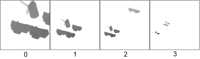
- Render the scene from the main camera. In order for the shadow to turn out to be a bit blurred, we will use the Percentage Closer Filtering algorithm. When calculating the shading of a point, we will take samples from all shadow maps and mix the result. As a result, we get a float value, where 0.0 would mean a fully shaded point, and 1.0 - not completely shaded. The functions on the HLSL for calculating shading are shown below.
float3 getShadowCoords(int splitIndex, float3 worldPos) { float4 coords = mul(float4(worldPos, 1), shadowViewProjection[splitIndex]); coords.xy = (coords.xy / coords.ww) * float2(0.5, -0.5) + float2(0.5, 0.5); return coords.xyz; } float sampleShadowMap(int index, float3 coords, float bias) { if (coords.x < 0 || coords.x > 1 || coords.y < 0 || coords.y > 1) return 1.0f; float3 uv = float3(coords.xy, index); float receiver = coords.z; float sum = 0.0; const int FILTER_SIZE = 3; const float HALF_FILTER_SIZE = 0.5 * float(FILTER_SIZE); for (int i = 0; i < FILTER_SIZE; i++) { for (int j = 0; j < FILTER_SIZE; j++) { float3 offset = float3(shadowBlurStep * (float2(i, j) - HALF_FILTER_SIZE) / HALF_FILTER_SIZE, 0); sum += shadowMap.SampleCmpLevelZero(shadowMapSampler, uv + offset, receiver - bias); } } return sum / (FILTER_SIZE * FILTER_SIZE); } float shadow(float3 worldPos) { float shadowValue = 0; [unroll(MAX_SPLITS)] for (int i = 0; i < splitsCount; i++) { float3 coords = getShadowCoords(i, worldPos); shadowValue += (1.0 - sampleShadowMap(i, coords, SHADOW_BIASES[i])); } return 1.0 - saturate(shadowValue); }
Finally, it is necessary to take into account the fact that, in addition to shadows, there is also shading from the lighting algorithm (I used the Blinna-Phong lighting model). To avoid double shading, I added the following code to the pixel shader.float shadowValue = shadow(input.worldPos); shadowValue = lerp(1, shadowValue, ndol);
Here the advantage is given to the lighting model, i.e. where it is dark according to the Blinna-Phong model, the shadow will not be superimposed. The decision does not claim to be ideal, but to some extent eliminates the problem.
As a result, we get the following picture.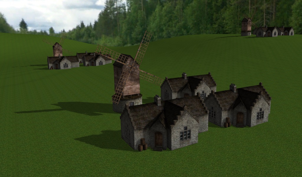

Implementation on OpenGL 4.3
To implement the algorithm on OpenGL 4.3, we need all the same as for Direct3D 11, but there are subtleties. In OpenGL, we can only
GL_DEPTH_COMPONENT32F samples with comparisons for textures that contain a depth value (for example, in the GL_DEPTH_COMPONENT32F format). Consequently, we will render the rendering only to the depth buffer, and write to color in color (more precisely, attach only the array of textures for storing the depth buffer to the framebuffer). On the one hand, this will save us a little bit of video memory and ease the graphics pipeline, on the other hand, it will force us to work with normalized depth values.OpenGL's selection parameters can be tied directly to the texture. They will be identical to those discussed earlier for Direct3D 11.
const float BORDER_COLOR[] = { 1.0f, 1.0f, 1.0f, 1.0f }; glBindTexture(m_shadowMap->getTargetType(), m_shadowMap->getDepthBuffer()); glTexParameteri(m_shadowMap->getTargetType(), GL_TEXTURE_MIN_FILTER, GL_LINEAR_MIPMAP_LINEAR); glTexParameteri(m_shadowMap->getTargetType(), GL_TEXTURE_MAG_FILTER, GL_LINEAR); glTexParameteri(m_shadowMap->getTargetType(), GL_TEXTURE_COMPARE_MODE, GL_COMPARE_REF_TO_TEXTURE); glTexParameteri(m_shadowMap->getTargetType(), GL_TEXTURE_COMPARE_FUNC, GL_LESS); glTexParameteri(m_shadowMap->getTargetType(), GL_TEXTURE_WRAP_S, GL_CLAMP_TO_BORDER); glTexParameteri(m_shadowMap->getTargetType(), GL_TEXTURE_WRAP_T, GL_CLAMP_TO_BORDER); glTexParameterfv(m_shadowMap->getTargetType(), GL_TEXTURE_BORDER_COLOR, BORDER_COLOR); glBindTexture(m_shadowMap->getTargetType(), 0); Interesting is the process of creating an array of textures, which inside OpenGL is represented by a three-dimensional texture. There is no special function for its creation, both of which are created using
glTexStorage3D . The analog of SV_RenderTargetArrayIndex in GLSL is the built-in variable gl_Layer .The rendering scheme also remained the same:
- Clear the shadow map array. Since there is no color channel in framebuffer, we will only clear the depth buffer. For a normalized depth buffer, the maximum value will be 1.0.
- Render shadow maps. Since only depth buffers are formed, we do not need a fragment shader.Vertex shader
#version 430 core const int MAX_SPLITS = 4; layout(location = 0) in vec3 position; layout(location = 1) in vec3 normal; layout(location = 2) in vec2 uv0; layout(location = 3) in vec3 tangent; layout(location = 4) in vec3 binormal; out VS_OUTPUT { float depth; flat int instanceID; } vsoutput; uniform mat4 modelMatrix; uniform mat4 shadowViewProjection[MAX_SPLITS]; uniform int shadowIndices[MAX_SPLITS]; void main() { vec4 wpos = modelMatrix * vec4(position, 1); vec4 pos = shadowViewProjection[shadowIndices[gl_InstanceID]] * vec4(wpos.xyz, 1); gl_Position = pos; vsoutput.depth = pos.z; vsoutput.instanceID = gl_InstanceID; }Geometric Shader#version 430 core const int MAX_SPLITS = 4; layout(triangles) in; layout(triangle_strip, max_vertices = 3) out; in VS_OUTPUT { float depth; flat int instanceID; } gsinput[]; uniform int shadowIndices[MAX_SPLITS]; void main() { for (int i = 0; i < gl_in.length(); i++) { gl_Position = gl_in[i].gl_Position; gl_Layer = shadowIndices[gsinput[i].instanceID]; EmitVertex(); } EndPrimitive(); } - Render the scene from the main camera. When calculating the shadows, the main thing to remember is to translate the distance between the current point and the light source (
coords.zin the code) into the range [0; 1] .vec3 getShadowCoords(int splitIndex, vec3 worldPos) { vec4 coords = shadowViewProjection[splitIndex] * vec4(worldPos, 1); coords.xyz = (coords.xyz / coords.w) * vec3(0.5) + vec3(0.5); return coords.xyz; }
As a result, we get a picture slightly different from Direct3D 11 (for the sake of interest, I’ll show it from a different angle).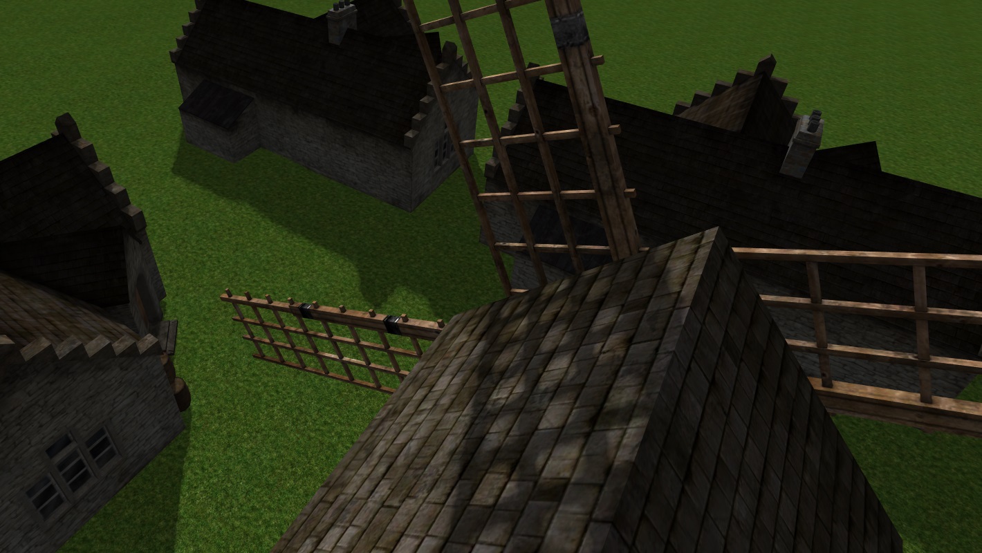
Problems
The shadow mapping algorithm and its modifications have many problems. Often, the algorithm has to be carefully customized for a particular game or even a specific scene. A list of the most frequent problems and their solutions can be found here . When implementing PSSM, I encountered the following:
- The disappearance of shadows from objects that are behind the observer. We position the shadow maps so that their coverage most closely matches the visibility pyramid from the main camera. Accordingly, the objects located behind the observer, simply will not get into them. I smoothed this artifact by entering into the algorithm for calculating the shadow matrices of the form-projection a shift in the direction opposite to the vector of vision. Although this certainly does not solve the problem in the case of long shadows at sunset or shadows from tall objects.
- Truncation of object shadows. If the object is large enough, it can be partially cut off when rendering shadow maps of the first segments. This can be solved by adjusting the position of the camera from which the shadow is rendered, and the shift from the previous point. With unsuccessful settings, you can see such an artifact.
- Erroneous self-shadowing. Probably the most famous graphic artifact that occurs when using shadow maps. This problem is quite successfully solved by introducing an error when comparing the value in the shadow map with the calculated value. In practice, I had to use individual error values for each shadow map. The figure below on the left shows the wrong choice of errors, on the right - the successful one.

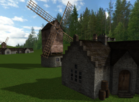
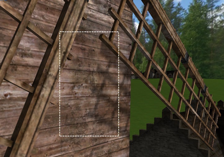
- Unfortunately, the elimination of erroneous self-shadowing by introducing an error when comparing depths leads to another artifact called Peter Panning (it can be roughly translated as “Peter Pan effect” into Russian). For those who do not remember the book, the shadow of Peter Pan lived their lives and often ran away from the owner. It looks like this (the shadow at the corner of the house is slightly shifted).
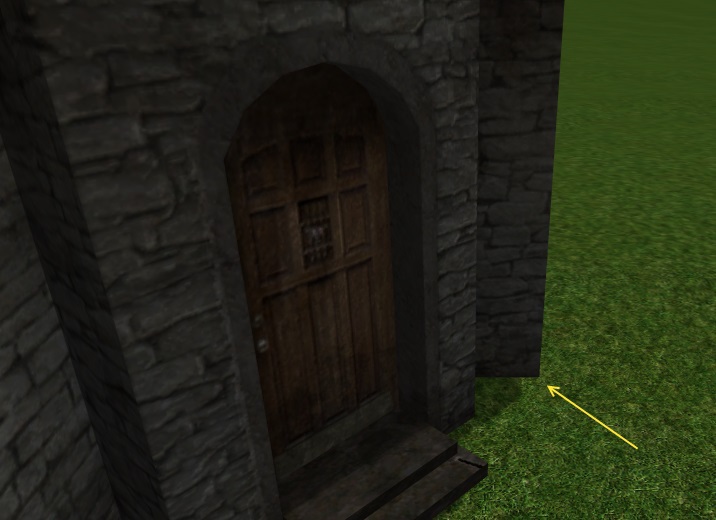
This artifact is sometimes quite difficult to notice, especially on objects of complex shape, but it is almost always there.
Performance
Performance measurements were taken on a computer with the following configuration: AMD Phenom II X4 970 3.79GHz, 16Gb RAM, AMD Radeon HD 7700 Series, running Windows 8.1.
Average frame time. Direct3D 11 / 1920x1080 / MSAA 8x / full screen / small scene (~ 12k polygons per frame, ~ 20 objects)
| Number of splits / Size of shadow map (N x N pixels) | 1024 | 2048 | 4096 |
|---|---|---|---|
| 2 | 4.5546ms | 5.07555ms | 7.1661ms |
| 3 | 5.50837ms | 6.18023ms | 9.75103ms |
| four | 6.00958ms | 7.23269ms | 12.1952ms |
Average frame time. OpenGL 4.3 / 1920x1080 / MSAA 8x / full screen / small scene (~ 12k polygons per frame, ~ 20 objects)
| Number of splits / Size of shadow map (N x N pixels) | 1024 | 2048 | 4096 |
|---|---|---|---|
| 2 | 3.2095ms | 4.05457ms | 6.06558ms |
| 3 | 3.9968ms | 4.87389ms | 8.65781ms |
| four | 4.68831ms | 5.93709ms | 10.4345ms |
Average frame time. 4 splits / 1920x1080 / MSAA 8x / full screen / large scene (~ 1000k polygons per frame, ~ 1000 objects, ~ 500 instances of objects)
| API / Shadow Map Size (N x N pixels) | 1024 | 2048 | 4096 |
|---|---|---|---|
| Direct3d 11 | 29.2031ms | 33.3434ms | 40.5429ms |
| Opengl 4.3 | 21.0032ms | 26.4095ms | 41.8098ms |
The results showed that on large and small scenes, the implementation on OpenGL 4.3 works, in general, faster. With an increase in the load on the graphics pipeline (an increase in the number of objects and their instances, an increase in the size of shadow maps), the difference in work speed between implementations is reduced. I associate the advantage of implementation on OpenGL with a method of forming a shadow map other than Direct3D 11 (we used only the depth buffer without writing to the color). Nothing prevents us from doing the same on Direct3D 11, while accepting the use of normalized depth values. However, this approach will work only as long as we do not want to store in the shadow map any additional data or function of the depth value instead of the depth value. And some improvements of the algorithm (for example, Variance Shadow Mapping ) will be difficult for us to implement.
findings
The PSSM algorithm is one of the most successful ways to create shadows in large open spaces. It is based on a simple and clear principle of splitting, which can be easily scaled by increasing or decreasing the quality of shadows. This algorithm can be combined with other shadow mapping algorithms for more beautiful soft shadows or more physically correct shadows. At the same time, shadow mapping algorithms often lead to the appearance of unpleasant graphic artifacts that must be eliminated by fine-tuning the algorithm for a particular game.
Source: https://habr.com/ru/post/226421/
All Articles