The method of self-determination of the response time of the LCD monitor screen or TV
“Who's stopping us will help us”
k / f "Caucasian Captive"
The response time of the LCD screen is one of the most important characteristics of the monitor and TV. It determines how well this monitor is suitable, for example, for computer games or watching videos. If the response time is too long, then on the screen behind moving high-contrast objects there will be visible artifacts perceived as "ghosts" or "shadows" that interfere with viewing. But, unlike most other technical specifications, the response time is difficult to measure. But this could be very useful, for example, when purchasing a new monitor or TV, as well as setting them up.
With other technical parameters, everything is more or less clear and obvious. For example, the screen size, if desired, can be measured with a tape measure or a ruler. The screen resolution and pixel size can also be “felt” by looking at the screen at close range. Many parameters (for example, screen brightness and contrast, black depth, uniformity of light, gradient display, sharpness, viewing angles, gamma and so on) can be checked using special test programs ranging from the simplest utilities like "Nokia Test " to programs for integrated configuration, verification and comparison, for example "LCD Vs_mon ".
')
But, unfortunately, the response time of the LCD screen is so easy to see and "touch" does not work, and it remains to be guided by the values specified by the manufacturer in the passport or advertising leaflet. But here, too, everything is quite confusing. There are different notions of response time: GtG (gray to gray, from gray to gray), BtW (black to white, from black to white), BtB or BWB (black-white-black, from black to white and back). In addition, each manufacturer measures the response time of the monitor using its own method, some of them use Overdrive overclocking technology to reduce response time, and therefore a direct comparison of monitors or TVs of different brands with each other may be incorrect.
So I would like to have some kind of tool with which the home (and even better in the store when buying) could be an objective measurement, based on it, to determine how well this TV or monitor is right for you.
Is there any way to do this?
In principle, of course you can, but ...
Here, for example, is a brief description of the method for measuring response time adopted at IXBT.COM :
Probably unlikely ...
Maybe it can be done somehow simpler, for example, using a regular camera or video camera? In principle, it is possible, but there are certain difficulties, problems associated both with the principle of image formation on the LCD matrix of a TV or monitor, and with the principles of fixing an image with a camera or video camera.
Here we need a little theory.
The image on the LCD matrix of a monitor or TV is formed from rows and columns of several million individual points, pixels , each of which in turn consists of a triad of colored subpixels.
For each pixel in accordance with its location, addressing is applied in rows and columns.
Information on switching a pixel is transmitted line by line, sequentially to all pixels of each row, and so sequentially row by row for the entire screen. Then the process starts again, the transfer of the next frame begins. Typically, in the LCD screens of monitors and televisions during such a cycle, the frame rate is 60 Hertz or more, that is, the frame refresh occurs every 16.7 milliseconds or less.
Accordingly, the pixels on the LCD matrix are not switched at a time, but line by line. Therefore, even within a single frame, at each moment of time, some of the pixels on the screen are already “old”, appeared as much as a few milliseconds ago and already had time to switch and change their brightness, some younger ones are in the process of switching, well, some have just appeared , and only going to switch.
Therefore, if we use high-speed shooting to try to fix what is happening on the surface of the whole screen from black to white, then in the photo we will get not a smooth gray tone, but a kind of gradient fill. Part of the screen has already changed color, and some have not yet.
In principle, of course, you can measure in Photoshop the brightness of pixels in different parts of the screenshot, by their position, and also, based on the frame and line frequency, determine the moment of their appearance, and based on this, try to calculate the response time by mathematical calculations, but the solution can hardly be called. Yes, and such a measurement is unlikely to be. Well, and for clarity and nothing to say ...
And not every camera will allow you to take such a picture.

And it's not just some special requirements for its speed, but in some features of the shutter and image fixing. For example, the above picture was taken by an old budget soap box with a central shutter, but in principle it is impossible to make a similar picture even with the most modern “SLR” with a curtain shutter.
Let us dwell on this in more detail.
First, a few words about the valves used in photo and video equipment.
Of all the variety of construction we will focus on the three most interesting ones for our further consideration.
The central shutter is located between the lens or right behind the rear lens. When it is triggered, the entire area of the photosensitive element is displayed immediately. The shutter speed is controlled by the open time of the shutter. Such a shutter has a relatively simple design, at any exposure provides a uniform exposure of the entire surface of the photosensitive element, so most of the compact digital cameras are equipped with various versions of such shutters. But since the central shutter is located inside the lens and makes it difficult to replace it, this design is extremely rare in cameras with interchangeable lenses.
The shutter is located directly near the film or photosensitive element. Since the shutter curtains begin to move from one edge to another, the exposure of the frame also occurs sequentially, from edge to edge. The speed of movement of the shutter curtains is kept strictly constant at any shutter speed, and the shutter speed is controlled by changing the size of the “slit”, the distance between the shutters during their movement (therefore, sometimes such a shutter is called curtain-slit).
Such a shutter is completely open only at shutter speed, more so-called sync shutter speed, X-Sync, which is indicated in the technical characteristics of the camera, and which is used when shooting with a flash. In this case, we will not shoot anything with the flash, but we still need this parameter.
Thus, even if shooting is done with a short flash (for example, 1/1000 seconds), the exposure of the entire frame will take much longer - from 1/30 second in old film mirrors and up to 1/200 second or less in modern digital ones.
Such a shutter is structurally much more complicated than the central one, somewhat capricious in operation, problems with uniform illumination may arise, but it allows you to easily replace the lens, and is able to provide very short exposures. Therefore, the curtain shutter is usually used in SLR cameras .
Finally, the third type of shutter, on which we will stop, is an electronic shutter . Strictly speaking, this is not a separate device, but simply the principle of dosing information of the photosensitive matrix. Directly in the open state, the information on the photosensitive matrix is first reset, then the matrix is exposed during the exposure time, and then the information is read. Such a shutter is structurally the simplest and, therefore, cheap, and therefore it is often used in the simplest photo and webcams and smartphones, and since it does not have mechanical parts and, consequently, noise and wear, it is often used for video recording with photo and video cameras even with another shutter.
The latter type of shutter is most important for our further consideration.
Now a few words about the photosensitive matrixes used in photo and video cameras.
Currently, for the shooting are mainly used light-sensitive matrix CCD and CMOS . Each of these types of matrices has its own characteristics, advantages and disadvantages. We dwell on only one of the features of each of these matrices, which is important for further understanding.
In a modern CCD matrix with column buffering (interline CCD), the captured frame is simultaneously read into a special light-protected frame buffer located in the matrix itself, and then relatively slowly pumped out from there for further processing.
In the CMOS matrix, the process of reading cell information occurs line by line, pixel by pixel, drain by line, much like the process of transferring information in the LCD matrix of a monitor or TV, which we discussed above.
Some conclusions important for further consideration.
Well, finally, we come to the main issue of the article, and still try to somehow fix, and then somehow measure the response time of the LCD matrix without using a high-speed camera or other special expensive equipment.
Since the frame change is a very fast process, it would seem that to fix it it would be best to use a camera with a central shutter. But as we found out, even an ideal camera capable of taking snapshots will not help us; we will need a series of shots taken at a frequency of at least 1000 frames per second. But we will try to go the other way, and get along with “improvised means”.
Imagine that the screen displays a picture of white and black rectangles that change places at some point in time:
 ->
-> 
As a result, we will see:

On the LCD screen, this happens not instantly, but for a certain period of time. With a refresh rate of 60 frames per second, this is 16.7 milliseconds.
Now imagine that we decided to photograph this process with a camera with a curtain or electronic shutter with a curtain movement from left to right, and in our camera the curtain moves relatively slowly, several times slower than the frame refresh rate on the LCD screen.
Consider a chain of events on the screen with the simultaneous imposition of a “slot” position in the camera blind:
one)  2)
2)
 3)
3)  four)
four)
Next begins the frame update:
 five)
five)  6)
6)
 7)
7)  eight)
Frame update ended:
9)  ten
ten
And so on ...
And now let us remember that in the photo we only recorded what happened, on the screen BEFORE THE MOMENT OF THE PASSAGE “gap”.
So:

Of course, this is a very simplified picture. In fact, the screen does not switch instantly, but during the response time (which we just want to determine) Yes, and frame scan and movement of the camera curtains are continuous, not steps, and therefore the photo will not be so glamorous.

Thus, in the photo we had captured the events occurring on the screen at different times during one frame, relatively speaking, a lot of narrow vertical “photos” taken one after another.
It remains to understand how to extract the information we need from this.
Suppose that the blind of the camera moves so slowly that during this time on the monitor screen the frame has time to change not two, but three times:
-> ->
In this case, the picture we would have:

Well, now we have fixed points for which we can attach to determine the time of the relevant events.
We know that at some point in time there was a change in the rectangles on the screen, and after another 16.7 milliseconds the opposite change occurred.
Thus, on any horizontal line in the picture, the distance between the beginning of the change in brightness of rectangles from black to white and from white to black is exactly 16.7 milliseconds.
If the beginning of the change in brightness is difficult to determine, then any other characteristic point can be chosen as a reference point, for example, the point where the brightness of the gradients coincides in the upper and lower bands.
Now we know what distance in the photo corresponds to a time interval of 16.7 milliseconds.
For simplicity, let us vertically divide our image into conditional time zones of equal width.
In the above case, it turned out that the time interval of 16.7 milliseconds takes 13 time zones. A small error in the definition in this case is not terrible, since it will be a fraction of a millisecond.
Consequently, one time zone corresponds to about 1.25 milliseconds.
Well, then everything is simple.
Let us measure horizontally the length of the front from white to black (BtW) and from black to white (WtB).
In this case, they coincided, and have a length of about 4 vertical time zones, that is, about 5 milliseconds.
The truth is only theoretically, on paper. It remains to create a test material with which we will work, and pick up equipment with which you can take a similar picture.
With the first, everything is quite simple.
Let's make a simple video for offline viewing * with alternating black and white stripes vertically like in the picture above, only at 60 frames per second. It is easy to see that every 16.7 milliseconds the horizontal bar shifts down by 1 step. Since in most displays the response time from black to white is much longer than from white to black, the stripes in the test in each horizontal line alternate not through one, but after three (one black and three white). Accordingly, the horizontals we got not two, but four. Thus, at each moment of time we have one black and three white stripes on the screen.
Well, for convenience, as well as to make it easier to catch defective images, two identical test zones were made one under one.
In the picture they should also be exactly the same (well, except perhaps with a slight horizontal displacement due to the frame scan of the monitor).
But if the picture is very large, or the length of the strips of the upper and lower test zones do not match, then something went wrong (for example, the photo came at the wrong time of the monitor frame change), and such a picture will have to be rejected.
To facilitate subsequent analysis, the video is vertically divided into 50 time zones. Vertical stripes combined, light / dark gray (10% / 90%). This should also facilitate further work with photography. When photographing it is not necessary that all zones fit into the frame. You can remove and 40, and 30, and even 20 zones. It’s not scary if there is not a whole number of time zones in the image, for example, 37.5 - this doesn’t affect the accuracy, just the conversion factor from the relative width of the time zone to milliseconds will be different.
Well, now go to the question
As we noted above, the duration of the photo frame must be longer than the duration of the frame on the display. For DSLRs and other cameras with a shutter, the duration of the photo frame is approximately equal to the sync speed.
And here the first ambush lurks us: modern cameras have a very short one. The sync speed is much shorter than 1/60 second.
Here the old Soviet “Zenith E” would be perfect, but unfortunately it is not digital.
But all is not lost - a similar picture can be taken with a camera with a fast curtain shutter, but there are specific features. But we'll talk about this in the next article.
In addition, modern mirrors usually have the ability to shoot video, so if you have a CMOS matrix, you can use this mode. The main thing is that the video mode is not very fast - no more than 30 frames per second. Well, the resolution for the video naturally need to choose the maximum. Firstly, to get the highest quality freeze frame, and secondly, to slow down the electronic shutter as much as possible.
The same requirements for video cameras: in this case, they should be approached with a maximum video mode of no more than 30 frames per second, a CMOS matrix and an electronic shutter. If the camcorder also uses an electronic shutter when taking photos, then you can try this mode.
And finally, digital cameras, smartphones and similar devices, which are usually considered unsuitable for serious work, can be perfect here.
The requirements are the same: CMOS matrix, and a rather slow electronic shutter.
The truth is, there is one more important requirement that will immediately eliminate half of the digital flashes: THE SHUTTER SHOULD BE SHALL AS SHORTLY AS SHED, at least 1/500 - 1/1000 seconds, and preferably even less. After all, 1/1000 of a second is 1 millisecond, i.e. comparable to the response time of the LCD monitor that we want to measure. Shooting with an exposure of more than 1/500 is the same as shooting an active child with an exposure of more than 1/30. Of course, we will be able to see something with a longer shutter speed, but it must be borne in mind that in this case, the shorter the shutter speed, the more accurate the result will be.

Such are the conflicting requirements for equipment for shooting.
But, nevertheless, suitable for this test photographic equipment can be found. For example, the camera of the Samsung Galaxy S GT-I9000 smartphone is quite good for the author of the article.
Let's try to determine the response time of the monitor with the TN matrix BenQ M2700HD .
Before testing, the monitor should be warm and well tuned to the levels of black and white. This can be done, for example, using the LCD Vs_mon program. If the black and white levels are inaccurately tuned, then the response time test will give the corresponding error. Rather, the test result will be correct, but for incorrectly set levels.
To get the shortest possible shutter speed, you need to set the maximum sensitivity to light (in this case ISO 800). With the same purpose, as well as to reduce the effect of PWM backlight lamps, it is advisable to calibrate the monitor during testing at the highest possible brightness.
So, we run an endless replay of the video playback in windowed mode, and take several screenshots.
Since the electronic shutter usually “moves” along the short side of the image, we position the camera in front of the screen so that the portrait image is obtained.
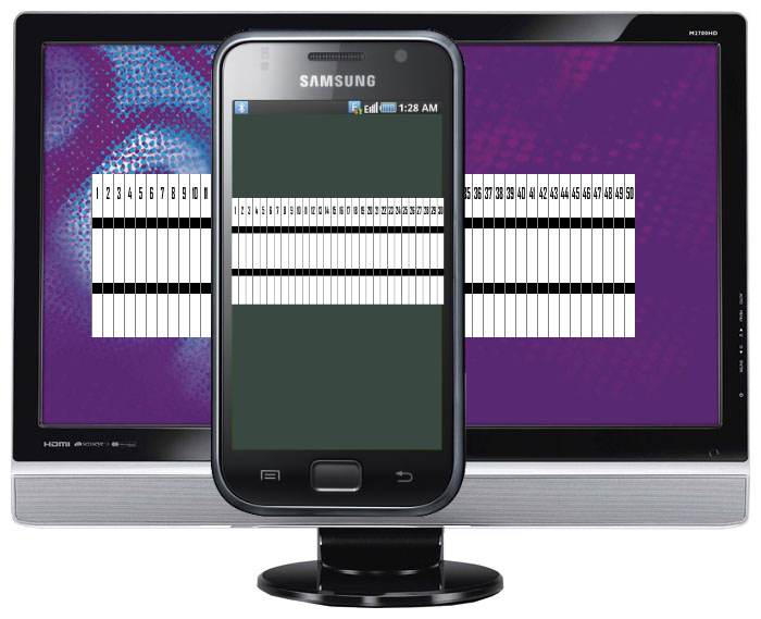
Screenshots of the monitor with TN matrix BenQ M2700HD , taken by the camera of the smartphone Samsung Galaxy S GT-I9000 .
The pictures above clearly show that although they differ in the width of the player’s window, the character of the lines corresponding to the frames on the LCD screen is exactly the same (well, except for the scale, of course) - in both cases there were four horizontal bars, each which corresponds to the next one by one frame on the monitor screen.
Since the frame rate of the monitor was 60 Hertz (16.7 milliseconds), by the presence of four horizontal bars in the frame, we can conclude that the total response time of the electronic shutter of this camera is about 65 milliseconds, which is a bit too much, but quite acceptable.
Any frame is suitable for further analysis.
But since in the second snapshot we already see the raster of the monitor matrix, we will consider the first snapshot.
For clarity, the picture is blurred in the photo editor, and conditional marks are applied to it, corresponding to the frame time and response time from 10% white to 90% black and from 90% black to 10% white (it’s clear now why vertical lines are made of exactly these shades). ).

If you enable Overdrive in the monitor settings, then the response time from black to white is significantly reduced.
We conducted the previous testing with the monitor brightness close to the maximum, and with optimal adjustment of the black and white levels. However, usually the monitor is operated at a much lower brightness, and the rest of the settings the user usually selects for themselves individually. And from this the result of the test can change significantly.
Let's try to check the response time of the same BenQ M2700HD monitor at the operational “office” setting (low brightness, black and white levels are calibrated to make all halftones visible in highlights and shadows).

Overdrive is off.
The response time from black to white increased to almost 20 milliseconds, i.e. It became more than one frame. It is here that it becomes clear why the alternation of one black and three white frames is made in the test video. In this case, this is a calibration fee with the distinctiveness of all halftones in highlights.
For “office” use, this is not terrible, but for “cinema” and even more “gaming” use, if behind high-contrast objects “ghosts” or “shadows” begin to appear, it may be worth sacrificing one or two gradations in highlights (shadows), to get rid of them.
In addition, the picture clearly shows the vertical slightly colored stripes of different rage. This flicker backlight with PWM regulation, due to the reduced brightness of the CCFL lamp, operating at incomplete power. Alas, this is also a fee for a comfortable brightness. Note that the “pencil test” this monitor passes without comment, so in reality, everything is not so scary.
Overdrive enabled.
The response time from black to white remains almost the same as at maximum brightness, but now after switching the strip becomes whiter than the white background. This is an artifact characteristic of the Overdrive display mode, also manifested due to the nature of the calibration.
Of course, this method is hardly applicable for professional testing of LCD monitors, and its result is less accurate than according to the method given at the beginning of the article. But on the other hand, it makes it quite easy to conduct such testing independently, without the use of special equipment, and the test result is very visual. This can be very useful when setting up and calibrating an existing monitor or TV, or when purchasing a new one.
k / f "Caucasian Captive"
Preamble
The response time of the LCD screen is one of the most important characteristics of the monitor and TV. It determines how well this monitor is suitable, for example, for computer games or watching videos. If the response time is too long, then on the screen behind moving high-contrast objects there will be visible artifacts perceived as "ghosts" or "shadows" that interfere with viewing. But, unlike most other technical specifications, the response time is difficult to measure. But this could be very useful, for example, when purchasing a new monitor or TV, as well as setting them up.
With other technical parameters, everything is more or less clear and obvious. For example, the screen size, if desired, can be measured with a tape measure or a ruler. The screen resolution and pixel size can also be “felt” by looking at the screen at close range. Many parameters (for example, screen brightness and contrast, black depth, uniformity of light, gradient display, sharpness, viewing angles, gamma and so on) can be checked using special test programs ranging from the simplest utilities like "Nokia Test " to programs for integrated configuration, verification and comparison, for example "LCD Vs_mon ".
')
But, unfortunately, the response time of the LCD screen is so easy to see and "touch" does not work, and it remains to be guided by the values specified by the manufacturer in the passport or advertising leaflet. But here, too, everything is quite confusing. There are different notions of response time: GtG (gray to gray, from gray to gray), BtW (black to white, from black to white), BtB or BWB (black-white-black, from black to white and back). In addition, each manufacturer measures the response time of the monitor using its own method, some of them use Overdrive overclocking technology to reduce response time, and therefore a direct comparison of monitors or TVs of different brands with each other may be incorrect.
So I would like to have some kind of tool with which the home (and even better in the store when buying) could be an objective measurement, based on it, to determine how well this TV or monitor is right for you.
Is there any way to do this?
In principle, of course you can, but ...
Here, for example, is a brief description of the method for measuring response time adopted at IXBT.COM :
TheoryCan this method be recommended for self-testing?
The response time for monitors is given in ISO 13406-2. The response time is the sum of the time required to change the relative brightness of the object from 0.1 to 0.9 (on time) and the time for reverse change (off time). The relative brightness is defined as the instantaneous difference (at the current time) and the minimum (the monitor is turned on, the video signal corresponding to the black field is supplied to the input) brightness, divided by the maximum difference (the monitor is turned on, the video signal corresponding to the white field is input) and the minimum brightness.
Practice
The hardware part of the response time measurement complex consists of a photo sensor that measures the relative brightness on the screen of the monitor under test, and a L-Card E-140 USB ADC (max. 100 kHz, operating at 10 kHz, 14 bits) for digitizing and entering data from the sensor to the computer, as well as the necessary cables ...
The software part of the complex is the GelTreat program, which allows to register and analyze time-response type dependencies modified to obtain response time values.
During the measurements, the GelTreat program launches two processes: the first registers the signal from the sensor, the second, in the DirectDraw mode, displays templates on the screen under test. Pages in the templates change after 500 ms for 10 seconds ...
On the record we get about 10 pulses. We process the last 5, where the monitor mode has already been precisely established ... As a result, horizontal red lines appear on the chart, marking 10% and 90% of the maximum response (brightness) ... In total, we define 5 intervals, then we calculate the average on and off times and their sum ...
Probably unlikely ...
Maybe it can be done somehow simpler, for example, using a regular camera or video camera? In principle, it is possible, but there are certain difficulties, problems associated both with the principle of image formation on the LCD matrix of a TV or monitor, and with the principles of fixing an image with a camera or video camera.
Here we need a little theory.
Theory
The image on the LCD matrix of a monitor or TV is formed from rows and columns of several million individual points, pixels , each of which in turn consists of a triad of colored subpixels.
For each pixel in accordance with its location, addressing is applied in rows and columns.
Information on switching a pixel is transmitted line by line, sequentially to all pixels of each row, and so sequentially row by row for the entire screen. Then the process starts again, the transfer of the next frame begins. Typically, in the LCD screens of monitors and televisions during such a cycle, the frame rate is 60 Hertz or more, that is, the frame refresh occurs every 16.7 milliseconds or less.
Accordingly, the pixels on the LCD matrix are not switched at a time, but line by line. Therefore, even within a single frame, at each moment of time, some of the pixels on the screen are already “old”, appeared as much as a few milliseconds ago and already had time to switch and change their brightness, some younger ones are in the process of switching, well, some have just appeared , and only going to switch.
Therefore, if we use high-speed shooting to try to fix what is happening on the surface of the whole screen from black to white, then in the photo we will get not a smooth gray tone, but a kind of gradient fill. Part of the screen has already changed color, and some have not yet.
In principle, of course, you can measure in Photoshop the brightness of pixels in different parts of the screenshot, by their position, and also, based on the frame and line frequency, determine the moment of their appearance, and based on this, try to calculate the response time by mathematical calculations, but the solution can hardly be called. Yes, and such a measurement is unlikely to be. Well, and for clarity and nothing to say ...
And not every camera will allow you to take such a picture.
And it's not just some special requirements for its speed, but in some features of the shutter and image fixing. For example, the above picture was taken by an old budget soap box with a central shutter, but in principle it is impossible to make a similar picture even with the most modern “SLR” with a curtain shutter.
Let us dwell on this in more detail.
First, a few words about the valves used in photo and video equipment.
Photo and video shutters
Of all the variety of construction we will focus on the three most interesting ones for our further consideration.
The central shutter is located between the lens or right behind the rear lens. When it is triggered, the entire area of the photosensitive element is displayed immediately. The shutter speed is controlled by the open time of the shutter. Such a shutter has a relatively simple design, at any exposure provides a uniform exposure of the entire surface of the photosensitive element, so most of the compact digital cameras are equipped with various versions of such shutters. But since the central shutter is located inside the lens and makes it difficult to replace it, this design is extremely rare in cameras with interchangeable lenses.
The shutter is located directly near the film or photosensitive element. Since the shutter curtains begin to move from one edge to another, the exposure of the frame also occurs sequentially, from edge to edge. The speed of movement of the shutter curtains is kept strictly constant at any shutter speed, and the shutter speed is controlled by changing the size of the “slit”, the distance between the shutters during their movement (therefore, sometimes such a shutter is called curtain-slit).
Such a shutter is completely open only at shutter speed, more so-called sync shutter speed, X-Sync, which is indicated in the technical characteristics of the camera, and which is used when shooting with a flash. In this case, we will not shoot anything with the flash, but we still need this parameter.
Thus, even if shooting is done with a short flash (for example, 1/1000 seconds), the exposure of the entire frame will take much longer - from 1/30 second in old film mirrors and up to 1/200 second or less in modern digital ones.
Such a shutter is structurally much more complicated than the central one, somewhat capricious in operation, problems with uniform illumination may arise, but it allows you to easily replace the lens, and is able to provide very short exposures. Therefore, the curtain shutter is usually used in SLR cameras .
Finally, the third type of shutter, on which we will stop, is an electronic shutter . Strictly speaking, this is not a separate device, but simply the principle of dosing information of the photosensitive matrix. Directly in the open state, the information on the photosensitive matrix is first reset, then the matrix is exposed during the exposure time, and then the information is read. Such a shutter is structurally the simplest and, therefore, cheap, and therefore it is often used in the simplest photo and webcams and smartphones, and since it does not have mechanical parts and, consequently, noise and wear, it is often used for video recording with photo and video cameras even with another shutter.
The latter type of shutter is most important for our further consideration.
Now a few words about the photosensitive matrixes used in photo and video cameras.
Photosensitive matrix
Currently, for the shooting are mainly used light-sensitive matrix CCD and CMOS . Each of these types of matrices has its own characteristics, advantages and disadvantages. We dwell on only one of the features of each of these matrices, which is important for further understanding.
In a modern CCD matrix with column buffering (interline CCD), the captured frame is simultaneously read into a special light-protected frame buffer located in the matrix itself, and then relatively slowly pumped out from there for further processing.
In the CMOS matrix, the process of reading cell information occurs line by line, pixel by pixel, drain by line, much like the process of transferring information in the LCD matrix of a monitor or TV, which we discussed above.
Some conclusions important for further consideration.
- The central shutter in combination with any type of matrix gives a snapshot taken at a single point in time.
- The curtain shutter in combination with any type of matrix gives a picture, different parts of which were exposed at a slightly different time, determined by the sync delay. Of course, the time difference is very small, but when shooting fast-moving objects or very fast processes, certain effects may occur. Usually they are negative (for example, the Rolling Shutter), but sometimes they can also be positive. But more on that below.
- The electronic shutter in combination with the CCD matrix gives a picture taken at a single point in time, but the electronic shutter in combination with the CMOS matrix gives a picture, different parts of which were exposed at a slightly different time, as when using the curtain shutter. Accordingly, the effects of this will be similar to the curtain.

Rolling shutter
Well, finally, we come to the main issue of the article, and still try to somehow fix, and then somehow measure the response time of the LCD matrix without using a high-speed camera or other special expensive equipment.
The author proposes exactly such a very accessible and fairly visual method.
Since the frame change is a very fast process, it would seem that to fix it it would be best to use a camera with a central shutter. But as we found out, even an ideal camera capable of taking snapshots will not help us; we will need a series of shots taken at a frequency of at least 1000 frames per second. But we will try to go the other way, and get along with “improvised means”.
Imagine that the screen displays a picture of white and black rectangles that change places at some point in time:
-> As a result, we will see:
On the LCD screen, this happens not instantly, but for a certain period of time. With a refresh rate of 60 frames per second, this is 16.7 milliseconds.
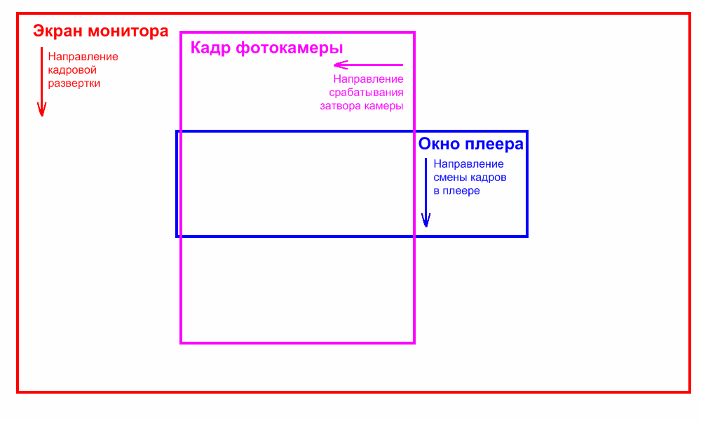
Now imagine that we decided to photograph this process with a camera with a curtain or electronic shutter with a curtain movement from left to right, and in our camera the curtain moves relatively slowly, several times slower than the frame refresh rate on the LCD screen.
Consider a chain of events on the screen with the simultaneous imposition of a “slot” position in the camera blind:
one) 2) 3) four)Next begins the frame update:
five) 6) 7) eight)Frame update ended:
9) tenAnd so on ...
And now let us remember that in the photo we only recorded what happened, on the screen BEFORE THE MOMENT OF THE PASSAGE “gap”.
So:
Of course, this is a very simplified picture. In fact, the screen does not switch instantly, but during the response time (which we just want to determine)
Yes, and frame scan and movement of the camera curtains are continuous, not steps, and therefore the photo will not be so glamorous.Thus, in the photo we had captured the events occurring on the screen at different times during one frame, relatively speaking, a lot of narrow vertical “photos” taken one after another.
So this is exactly what we need!
It remains to understand how to extract the information we need from this.
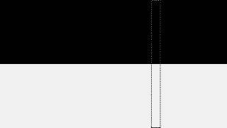
Suppose that the blind of the camera moves so slowly that during this time on the monitor screen the frame has time to change not two, but three times:
-> -> In this case, the picture we would have:
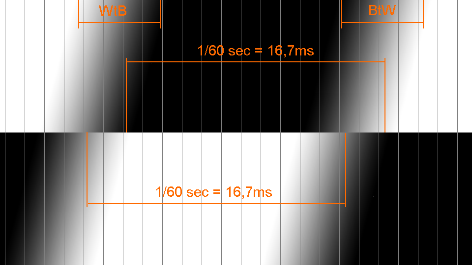
Well, now we have fixed points for which we can attach to determine the time of the relevant events.
We know that at some point in time there was a change in the rectangles on the screen, and after another 16.7 milliseconds the opposite change occurred.
Thus, on any horizontal line in the picture, the distance between the beginning of the change in brightness of rectangles from black to white and from white to black is exactly 16.7 milliseconds.
If the beginning of the change in brightness is difficult to determine, then any other characteristic point can be chosen as a reference point, for example, the point where the brightness of the gradients coincides in the upper and lower bands.
Now we know what distance in the photo corresponds to a time interval of 16.7 milliseconds.
For simplicity, let us vertically divide our image into conditional time zones of equal width.
In the above case, it turned out that the time interval of 16.7 milliseconds takes 13 time zones. A small error in the definition in this case is not terrible, since it will be a fraction of a millisecond.
Consequently, one time zone corresponds to about 1.25 milliseconds.
Well, then everything is simple.
Let us measure horizontally the length of the front from white to black (BtW) and from black to white (WtB).
In this case, they coincided, and have a length of about 4 vertical time zones, that is, about 5 milliseconds.
THE TASK SET IN THE HEADING OF THE ARTICLE IS SOLVED!
The truth is only theoretically, on paper. It remains to create a test material with which we will work, and pick up equipment with which you can take a similar picture.
With the first, everything is quite simple.
Let's make a simple video for offline viewing * with alternating black and white stripes vertically like in the picture above, only at 60 frames per second. It is easy to see that every 16.7 milliseconds the horizontal bar shifts down by 1 step. Since in most displays the response time from black to white is much longer than from white to black, the stripes in the test in each horizontal line alternate not through one, but after three (one black and three white). Accordingly, the horizontals we got not two, but four. Thus, at each moment of time we have one black and three white stripes on the screen.
Well, for convenience, as well as to make it easier to catch defective images, two identical test zones were made one under one.
In the picture they should also be exactly the same (well, except perhaps with a slight horizontal displacement due to the frame scan of the monitor).
But if the picture is very large, or the length of the strips of the upper and lower test zones do not match, then something went wrong (for example, the photo came at the wrong time of the monitor frame change), and such a picture will have to be rejected.
To facilitate subsequent analysis, the video is vertically divided into 50 time zones. Vertical stripes combined, light / dark gray (10% / 90%). This should also facilitate further work with photography. When photographing it is not necessary that all zones fit into the frame. You can remove and 40, and 30, and even 20 zones. It’s not scary if there is not a whole number of time zones in the image, for example, 37.5 - this doesn’t affect the accuracy, just the conversion factor from the relative width of the time zone to milliseconds will be different.
- Small addition
If you have a monitor with a very slow matrix, which does not have time to switch from white to black during one frame, you can try to use this video . Here the cycle takes 6 frames. The top 6 “frame-by-frame” bars can be used to determine the reference points on the frame, and the bottom 2 “three-frame” bars to measure the response time of monitors with a “slow” LCD matrix. Of course, there will be a few more defects when shooting (it will be necessary to select images where the entire transition is visible on the lower bars), but you can test monitors with a long response time from white to black.
Well, now go to the question
what are we going to shoot
As we noted above, the duration of the photo frame must be longer than the duration of the frame on the display. For DSLRs and other cameras with a shutter, the duration of the photo frame is approximately equal to the sync speed.
And here the first ambush lurks us: modern cameras have a very short one. The sync speed is much shorter than 1/60 second.
Here the old Soviet “Zenith E” would be perfect, but unfortunately it is not digital.
But all is not lost - a similar picture can be taken with a camera with a fast curtain shutter, but there are specific features. But we'll talk about this in the next article.
In addition, modern mirrors usually have the ability to shoot video, so if you have a CMOS matrix, you can use this mode. The main thing is that the video mode is not very fast - no more than 30 frames per second. Well, the resolution for the video naturally need to choose the maximum. Firstly, to get the highest quality freeze frame, and secondly, to slow down the electronic shutter as much as possible.
The same requirements for video cameras: in this case, they should be approached with a maximum video mode of no more than 30 frames per second, a CMOS matrix and an electronic shutter. If the camcorder also uses an electronic shutter when taking photos, then you can try this mode.
And finally, digital cameras, smartphones and similar devices, which are usually considered unsuitable for serious work, can be perfect here.
The requirements are the same: CMOS matrix, and a rather slow electronic shutter.
The truth is, there is one more important requirement that will immediately eliminate half of the digital flashes: THE SHUTTER SHOULD BE SHALL AS SHORTLY AS SHED, at least 1/500 - 1/1000 seconds, and preferably even less. After all, 1/1000 of a second is 1 millisecond, i.e. comparable to the response time of the LCD monitor that we want to measure. Shooting with an exposure of more than 1/500 is the same as shooting an active child with an exposure of more than 1/30. Of course, we will be able to see something with a longer shutter speed, but it must be borne in mind that in this case, the shorter the shutter speed, the more accurate the result will be.
Such are the conflicting requirements for equipment for shooting.
But, nevertheless, suitable for this test photographic equipment can be found. For example, the camera of the Samsung Galaxy S GT-I9000 smartphone is quite good for the author of the article.
Let's try to determine the response time of the monitor with the TN matrix BenQ M2700HD .
Before testing, the monitor should be warm and well tuned to the levels of black and white. This can be done, for example, using the LCD Vs_mon program. If the black and white levels are inaccurately tuned, then the response time test will give the corresponding error. Rather, the test result will be correct, but for incorrectly set levels.
To get the shortest possible shutter speed, you need to set the maximum sensitivity to light (in this case ISO 800). With the same purpose, as well as to reduce the effect of PWM backlight lamps, it is advisable to calibrate the monitor during testing at the highest possible brightness.
So, we run an endless replay of the video playback in windowed mode, and take several screenshots.
Since the electronic shutter usually “moves” along the short side of the image, we position the camera in front of the screen so that the portrait image is obtained.
Screenshots of the monitor with TN matrix BenQ M2700HD , taken by the camera of the smartphone Samsung Galaxy S GT-I9000 .
The pictures above clearly show that although they differ in the width of the player’s window, the character of the lines corresponding to the frames on the LCD screen is exactly the same (well, except for the scale, of course) - in both cases there were four horizontal bars, each which corresponds to the next one by one frame on the monitor screen.
Since the frame rate of the monitor was 60 Hertz (16.7 milliseconds), by the presence of four horizontal bars in the frame, we can conclude that the total response time of the electronic shutter of this camera is about 65 milliseconds, which is a bit too much, but quite acceptable.
Any frame is suitable for further analysis.
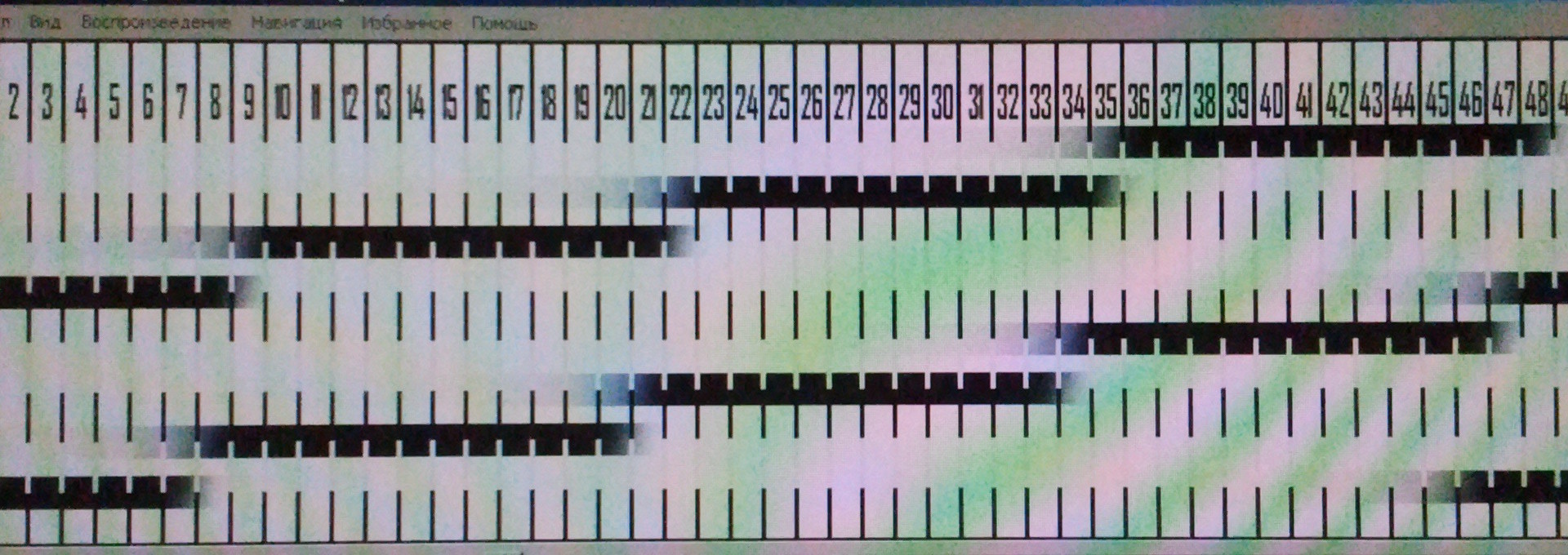
But since in the second snapshot we already see the raster of the monitor matrix, we will consider the first snapshot.
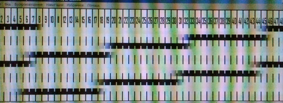
For clarity, the picture is blurred in the photo editor, and conditional marks are applied to it, corresponding to the frame time and response time from 10% white to 90% black and from 90% black to 10% white (it’s clear now why vertical lines are made of exactly these shades). ).
- It can be seen that the length of the frame (16.7 milliseconds) in a picture luring vertical time about 13 s x zones.
- Thus, a one time as I zone in the picture turned out 1,285 milliseconds in length
- The response time from white to black takes approximately one temporal y th zone, i.e. about 1.3 milliseconds.
- The response time from black to white is significantly longer, which is typical of TN matrices. In this case fall to 10% white (visible on the "disappearance" vertical stripes) took approximately 3 temporal s e zones, i.e. 4 milliseconds.
If you enable Overdrive in the monitor settings, then the response time from black to white is significantly reduced.
Thus, the task set in the title of the article was solved not only in theory, but also in practice!
We conducted the previous testing with the monitor brightness close to the maximum, and with optimal adjustment of the black and white levels. However, usually the monitor is operated at a much lower brightness, and the rest of the settings the user usually selects for themselves individually. And from this the result of the test can change significantly.
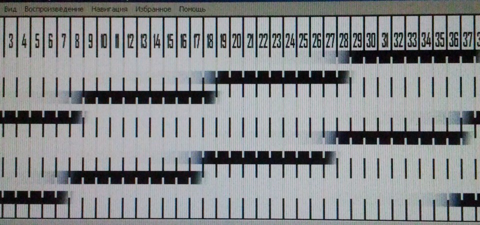
Let's try to check the response time of the same BenQ M2700HD monitor at the operational “office” setting (low brightness, black and white levels are calibrated to make all halftones visible in highlights and shadows).
Overdrive is off.
The response time from black to white increased to almost 20 milliseconds, i.e. It became more than one frame. It is here that it becomes clear why the alternation of one black and three white frames is made in the test video. In this case, this is a calibration fee with the distinctiveness of all halftones in highlights.
For “office” use, this is not terrible, but for “cinema” and even more “gaming” use, if behind high-contrast objects “ghosts” or “shadows” begin to appear, it may be worth sacrificing one or two gradations in highlights (shadows), to get rid of them.
In addition, the picture clearly shows the vertical slightly colored stripes of different rage. This flicker backlight with PWM regulation, due to the reduced brightness of the CCFL lamp, operating at incomplete power. Alas, this is also a fee for a comfortable brightness. Note that the “pencil test” this monitor passes without comment, so in reality, everything is not so scary.
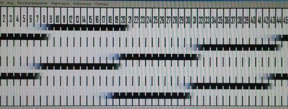
Overdrive enabled.
The response time from black to white remains almost the same as at maximum brightness, but now after switching the strip becomes whiter than the white background. This is an artifact characteristic of the Overdrive display mode, also manifested due to the nature of the calibration.
And a few words in conclusion
Of course, this method is hardly applicable for professional testing of LCD monitors, and its result is less accurate than according to the method given at the beginning of the article. But on the other hand, it makes it quite easy to conduct such testing independently, without the use of special equipment, and the test result is very visual. This can be very useful when setting up and calibrating an existing monitor or TV, or when purchasing a new one.
Source: https://habr.com/ru/post/225829/
All Articles