MIDI Wavy: make controlled color music using Arduino and MIDI
Hello. This manual describes the process of building controlled via MIDI-controller (or midi-track in any sequencer) color music on the Arduino. Initially, I made this device for visualizing a live performance; 2 modes of operation are proposed: live play and MIDI track playback.
The article is designed for beginners - everything that is needed is explained by the available, more advanced can simply get acquainted with this method of implementation, and, perhaps, use it in creating their own art installations or use it to dynamically control the light. Knowing programming languages is not necessary.
MIDI Wavy will consist of:
')

The path from pressing the key to the moment the LED lights up:
MIDI controller → Ableton Live (with ASIO) → LoopBe1 → Hairless MIDI <-> Serial Bridge → Arduino → LED torch
Instead of a MIDI controller, you can use a computer keyboard in a sequencer.
The lantern is made of LED strip 5050 with WS2811 chip , 5 diodes on the lantern. WS2811 allows you to control each LED separately, besides, the tape with capacitors is already soldered at the factory, and at the output we have 3 DIN , 5V , GND pins . Sold as without protection, and with a protective transparent silicone case. To create a presentable device, it is best to use 3-pin connectors. They are convenient to use, simplifying the removal of LEDs from the system.

(for example, “15 cm JR 3pin servo extension for servo”. choose the length according to taste)
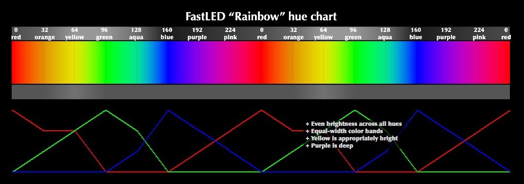
In the Arduino sketch, we include the FastLED library. It is recommended that you familiarize yourself with interesting documentation , where you can find the color code and other useful information.
The first time I did something like the one shown below. Soldering all the lights, you need to check every work:

(this is an old version of a flashlight without a magic connector, just soldered wires from the arduino set, but the meaning does not change)
The emulator is needed when we want to connect a sequencer (let Ableton Live) with our color music to control the change of the light pattern in real time, or to play the recorded change. Anyone will do, but I took LoopBe1 (http://www.nerds.de/en/loopbe1.html) . Install, reboot, open the sequencer. The essence of the sequencer setting is to make an output from the sequencer to the virtual MIDI channel, in order to connect this channel with the Arduino.
Go to the settings Ableton Live, or in any other, and configure the MIDI-OUTPUT output to our MIDI-emulator:
Using the hairless-midiserial program (http://projectgus.imtqy.com/hairless-midiserial/), we create the Serial <-> MIDI bridge (the values from the emulator / controller will be transmitted via the Serial-port):

As you can see, MIDI In is the entrance to the bridge, Serial port is the output from the bridge to the Arduino. In this setting, you can directly connect any MIDI controller, for example a MIDI keyboard, but to be honest, the keyboard did not want to work directly with me, apparently you need some kind of special. application, let's deal with it whenever possible somehow, but control of light through a midi + sequencer is more convenient. Of the minuses - the sequencer program can load quite slowly.
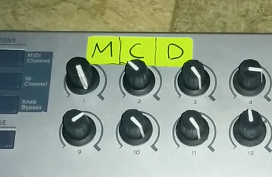
Absolutely anyone will fit (depending on your tasks, of course) a controller that you can buy at a music store, or you can assemble it yourself (there are instructions on the Internet how to do this). And if you are writing electronic music, then you probably have such a keyboard. You can use both the keys and the keys themselves. Each key (note) "hangs" the execution of certain commands, similarly with twists. In this example, 3 twists (denoted by Master, Color, Delay) and four octave notes are used.
In Ableton, FL Studio, etc. you can do without a MIDI controller. In these programs, you can use a regular PC keyboard as a piano.
For a prototype device, it is enough to connect everything on one small breadboard. In the future, it will not be difficult to replace the prototype board with a printed circuit board (soldering all that is necessary will not fall off). Cases for the device are in some stores with arduino or radio engineering, aluminum, cost from ~ 300


Unsafe breadboard SYB-170 10x17 holes 60P ; Aluminum case 100 * 76 * 35 mm, golden. 300 rub .
The directivity of the radiation of LEDs can be set using reflectors of arbitrary types. At will it is possible to fasten any reflector which you can. I took a plastic corner for the walls - it is matte, white and well illuminated. One inside (let it be lower) will be glued with aluminum tape (or some kind of mirror), and the other will be left. Direct the radiation to the non-pasted side, get a frosted glow of the reflector, and limited (ie it will seem that all or some part of the reflector is shining, depending on the proportions of the length of the reflector to the length of the tape). It is not necessary to glue the tape, but then the reflection coefficient will be less. It is possible on the contrary, to paste over all areas of the reflector.

There are reflectors with different textures that affect the shape of the radiation, but we will not consider them.
To begin with, we will connect the necessary libraries, set the type byte to all variables (it stores from 0 to 255, we just need the values, the rest will not be used):
Lantern designation:
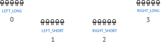
(Note: 0, 1, 2, 3 - numbers of cells in the array)
Code, part 2. Set the setup () function:
This method of marking LED strips is necessary for simultaneous control of each tape independently of the other. Read more on the FastLED library documentation page .
The fact is that 8-bit controllers do not support multi-threading, the code is executed sequentially. Piling up code slows down its execution. This method of connecting and working with LEDs (we will consider further) in some sense solves this problem, the program slows down less, and therefore each keystroke will be taken into account (from experience I’ll say that I used to do it differently and there were a lot of jambs with passing note due to delays or misalignments). In addition, changing the properties of LEDs is much more convenient by this method.
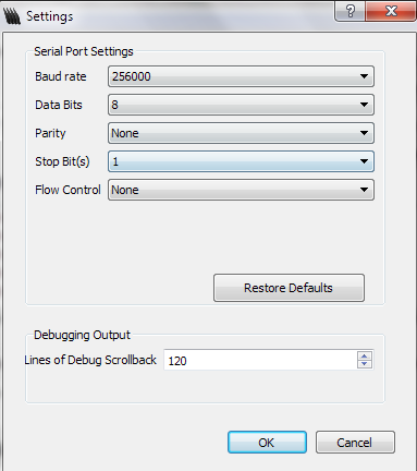
We start the Serial-port through which the microcontroller will communicate with the computer. We specify 256000. In the settings of Hairless Bridge we specify the same speed .
Let's create a couple of functions that will turn on and off the LEDs with certain settings:
Define the function of working with MIDI commands:
Comments on the code: as you noticed, when you press a key, a certain LED lights up, several simultaneously pressed keys will give a continuous glow, for example, one of the tapes, until the key is released. This allows you to create smooth transitions from one LED to another, creating a loop.
It happens that the LED hangs and does not turn off, for this purpose it was assigned to note 37 "RESET, DISABLE ALL LEDS".
The values in the MIDI commands can be taken from here (http://www.midi.org/techspecs/midimessages.php) , or you can directly track the key pressed in the hairless-midiserial :

You can (but not necessarily) add another function - a simple transfusion of all LEDs with color. Then the device can be used as a night light:
Code, part 5. And the final touch, set the loop () function:
The “longer” the notes that you press / insert, the more blurry the picture is due to the ghost effect being created:
Consider an example.
Duplicate the notes several times, and each time we lower the Velocity notes by a certain level, say 25%. In this case, you can specify the tail more precisely:
The most expensive - LEDs and a microcontroller. In general, if you are in the subject line, then in terms of arduino, you can use cheaper things.
Basically it is the lighting design of installations, concerts, structures, etc. Restriction on fantasy. For example, I use MIDI Wavy to highlight my tracks. LEDs help to give a special atmosphere and drive to the music, but look - do not kill people with epilepsy. It is desirable to use it with smoke, then the radiation picture looks much more powerful and cooler.
I use the simplified version of the control without the midi controller in the backlight of my bike, but about it later.
You can twist this case for learning to play the piano, or for your child's color programming, or to improve his memory (although such toys are sold in stores and they are much more compact, but we are not looking for easy ways).
If you are interested, I wish you good luck in your endeavors! Be sure to send a link to your work.
The article is designed for beginners - everything that is needed is explained by the available, more advanced can simply get acquainted with this method of implementation, and, perhaps, use it in creating their own art installations or use it to dynamically control the light. Knowing programming languages is not necessary.
Table of contents
- Visual model
- Components
- LED lights
- Library for working with LED
- MIDI emulator and sequencer
- Arduino Communications - MIDI Controller
- MIDI controller
- Bread board
- Reflectors
- Software part
- Ribbon Animation Example
- findings
- Demo video
- Files
MIDI Wavy will consist of:
- 4 homemade LED lights,
- 4 3-pin connectors of different lengths (50 and 30 cm) for communication LED <-> microcontroller,
- microcontroller (for example, arduino),
- breadboard (enough is enough)
- any MIDI controller
- emulator (namely - Ableton Live + loopBe1)
')
§ 1. Visual model
The path from pressing the key to the moment the LED lights up:
MIDI controller → Ableton Live (with ASIO) → LoopBe1 → Hairless MIDI <-> Serial Bridge → Arduino → LED torch
Instead of a MIDI controller, you can use a computer keyboard in a sequencer.
§ 2. Components
§ 2.1. LED lights
The lantern is made of LED strip 5050 with WS2811 chip , 5 diodes on the lantern. WS2811 allows you to control each LED separately, besides, the tape with capacitors is already soldered at the factory, and at the output we have 3 DIN , 5V , GND pins . Sold as without protection, and with a protective transparent silicone case. To create a presentable device, it is best to use 3-pin connectors. They are convenient to use, simplifying the removal of LEDs from the system.
(for example, “15 cm JR 3pin servo extension for servo”. choose the length according to taste)
§ 2.2. Library for working with LED
In the Arduino sketch, we include the FastLED library. It is recommended that you familiarize yourself with interesting documentation , where you can find the color code and other useful information.
The first time I did something like the one shown below. Soldering all the lights, you need to check every work:
Show Arduino sketch to check LED
#include "FastLED.h" #define NUM_LEDS 5 // 5 #define DATA_PIN 6 // 6- DIN ( ) // CRGB leds[NUM_LEDS]; void setup() { FastLED.addLeds<NEOPIXEL, DATA_PIN>(leds, NUM_LEDS); // } void loop() { FastLED.showColor(CHSV(190,255,255)); // } (this is an old version of a flashlight without a magic connector, just soldered wires from the arduino set, but the meaning does not change)
§ 2.3. MIDI emulator and sequencer
The emulator is needed when we want to connect a sequencer (let Ableton Live) with our color music to control the change of the light pattern in real time, or to play the recorded change. Anyone will do, but I took LoopBe1 (http://www.nerds.de/en/loopbe1.html) . Install, reboot, open the sequencer. The essence of the sequencer setting is to make an output from the sequencer to the virtual MIDI channel, in order to connect this channel with the Arduino.
Go to the settings Ableton Live, or in any other, and configure the MIDI-OUTPUT output to our MIDI-emulator:
Show Sequencer Settings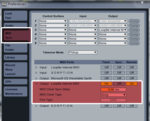
In the sequencer we create 2 MIDI tracks. On the first one, we put any synthesizer (I advise Drum Rack, because you can conveniently customize the names of the keys, which will help you navigate through all this more easily), then do MUTE on it (you can really not do it if you want to work directly on this track) , and the second is left blank, we do the following setting:
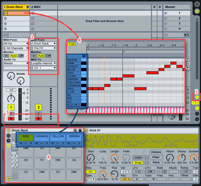
Activate the I / O button (item 2 in the figure), set the settings for the second track (item 1).
Hold down the CTRL button and activate both tracks (point 3 in the figure). Is done. Pay attention to paragraph 4 in the figure, this is exactly what I said, then it will be convenient to work with it. For example, through the editor of notes.
In the figure above, the same kind of note map as presented in area No. 4 can be achieved as follows: throw any audio file into the Drum Rack cell (I used kick.wav), right-click on it, “Rename” (or CTRL) + R).
This is a sound card emulator, with it you can get a very low delay between pressing a key and the result of signal processing (for comparison, on the basic settings of the sequencer, if you switch between keys a lot and quickly, there will be a delay between pressing a key and starting the LED) .
You can find it on the official site , freely available.
In the sequencer we create 2 MIDI tracks. On the first one, we put any synthesizer (I advise Drum Rack, because you can conveniently customize the names of the keys, which will help you navigate through all this more easily), then do MUTE on it (you can really not do it if you want to work directly on this track) , and the second is left blank, we do the following setting:
Activate the I / O button (item 2 in the figure), set the settings for the second track (item 1).
- MIDI From: 1-Drum Rack (specify from where to "take the signal" - from the first track).
- Pre FX (any value can be used, but Pre FX is used so that the effects from the first round go at the same time as the second one, it is better to read more on the Internet, in this problem it does not matter).
- Monitor: Auto
- MIDI To: LoopBe Internal MIDI (choose the name of the MIDI emulator)
- Ch: 1. (by default, the first (first) channel is used. In total, 16 channels are available, that is, as many as 16 layers of midi messages (notes). It is useful to use different channels when creating a more complex LED control system).
Hold down the CTRL button and activate both tracks (point 3 in the figure). Is done. Pay attention to paragraph 4 in the figure, this is exactly what I said, then it will be convenient to work with it. For example, through the editor of notes.
In the figure above, the same kind of note map as presented in area No. 4 can be achieved as follows: throw any audio file into the Drum Rack cell (I used kick.wav), right-click on it, “Rename” (or CTRL) + R).
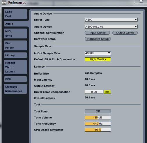
Optional: ASIO Driver
This is a sound card emulator, with it you can get a very low delay between pressing a key and the result of signal processing (for comparison, on the basic settings of the sequencer, if you switch between keys a lot and quickly, there will be a delay between pressing a key and starting the LED) .
You can find it on the official site , freely available.
Creating a MIDI track
↑ Let’s go into the arranging mode, the more expensive the LED must be the None option in step 2 in the figure, otherwise the MIDI clip cannot be created. Select the zone and create a new clip.
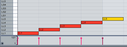
↑ Add notes. For example, the figure above shows the alternate switching of the LEDs on the LEFT_LONG tape. As soon as the note ends, the LED turns off immediately. It turns out a sharp flicker of the tape in one direction:

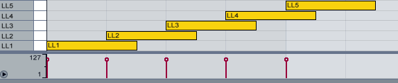
↑ By lengthening the notes, you can create a loop that is more pleasant to contemplate than just alternating the working LED:

By changing the value of beats per minute, you can change the track playback speed:

If we want to make music, then simply add an audio track with an audio file as you need (dragging it to the workspace). To make the light go in sync with the music, make a Warp sound clip. More details.
↑ Let’s go into the arranging mode, the more expensive the LED must be the None option in step 2 in the figure, otherwise the MIDI clip cannot be created. Select the zone and create a new clip.
↑ Add notes. For example, the figure above shows the alternate switching of the LEDs on the LEFT_LONG tape. As soon as the note ends, the LED turns off immediately. It turns out a sharp flicker of the tape in one direction:
↑ By lengthening the notes, you can create a loop that is more pleasant to contemplate than just alternating the working LED:
By changing the value of beats per minute, you can change the track playback speed:
If we want to make music, then simply add an audio track with an audio file as you need (dragging it to the workspace). To make the light go in sync with the music, make a Warp sound clip. More details.
Arduino Communications - MIDI Controller
Using the hairless-midiserial program (http://projectgus.imtqy.com/hairless-midiserial/), we create the Serial <-> MIDI bridge (the values from the emulator / controller will be transmitted via the Serial-port):
As you can see, MIDI In is the entrance to the bridge, Serial port is the output from the bridge to the Arduino. In this setting, you can directly connect any MIDI controller, for example a MIDI keyboard, but to be honest, the keyboard did not want to work directly with me, apparently you need some kind of special. application, let's deal with it whenever possible somehow, but control of light through a midi + sequencer is more convenient. Of the minuses - the sequencer program can load quite slowly.
§ 2.4. MIDI controller
Absolutely anyone will fit (depending on your tasks, of course) a controller that you can buy at a music store, or you can assemble it yourself (there are instructions on the Internet how to do this). And if you are writing electronic music, then you probably have such a keyboard. You can use both the keys and the keys themselves. Each key (note) "hangs" the execution of certain commands, similarly with twists. In this example, 3 twists (denoted by Master, Color, Delay) and four octave notes are used.
In Ableton, FL Studio, etc. you can do without a MIDI controller. In these programs, you can use a regular PC keyboard as a piano.
§ 2.5. Bread board
For a prototype device, it is enough to connect everything on one small breadboard. In the future, it will not be difficult to replace the prototype board with a printed circuit board (soldering all that is necessary will not fall off). Cases for the device are in some stores with arduino or radio engineering, aluminum, cost from ~ 300
Unsafe breadboard SYB-170 10x17 holes 60
§ 3. Reflectors
The directivity of the radiation of LEDs can be set using reflectors of arbitrary types. At will it is possible to fasten any reflector which you can. I took a plastic corner for the walls - it is matte, white and well illuminated. One inside (let it be lower) will be glued with aluminum tape (or some kind of mirror), and the other will be left. Direct the radiation to the non-pasted side, get a frosted glow of the reflector, and limited (ie it will seem that all or some part of the reflector is shining, depending on the proportions of the length of the reflector to the length of the tape). It is not necessary to glue the tape, but then the reflection coefficient will be less. It is possible on the contrary, to paste over all areas of the reflector.
There are reflectors with different textures that affect the shape of the radiation, but we will not consider them.
§ 4. Software part
Arduino sketch
To begin with, we will connect the necessary libraries, set the type byte to all variables (it stores from 0 to 255, we just need the values, the rest will not be used):
Show code part 1
// MIDI Wavy // JVLNS.ORG 2014 // #include "FastLED.h" // , #define LEFT_LONG 7 #define LEFT_SHORT 6 #define RIGHT_SHORT 5 #define RIGHT_LONG 4 #define NUM_STRIPS 4 // #define NUM_LEDS_PER_STRIP 5 // 1 // CRGB leds[NUM_STRIPS][NUM_LEDS_PER_STRIP]; // , byte colors[] = {0, 32, 64, 96, 128, 160, 192, 224, 239 }; // Master () - byte ColorBasic = 0; byte Master = 255; byte commandByte; // MIDI-, (noteOn, noteOff, Controller) byte noteByte; // ( ) byte velocityByte; // — ( noteOn/Off velocity (https://www.ableton.com/en/manual/editing-midi-notes-and-velocities), Controller — ). byte velocityByte1; // map() 0-127 0-255 byte noteOn = 144; // byte noteOff = 128; // byte faza = 0; // delay(faza) Lantern designation:
(Note: 0, 1, 2, 3 - numbers of cells in the array)
Code, part 2. Set the setup () function:
void setup() { // Serial- 256000 Serial.begin(256000); FastLED.addLeds<NEOPIXEL, LEFT_LONG>(leds[0], NUM_LEDS_PER_STRIP); FastLED.addLeds<NEOPIXEL, LEFT_SHORT>(leds[1], NUM_LEDS_PER_STRIP); FastLED.addLeds<NEOPIXEL, RIGHT_SHORT>(leds[2], NUM_LEDS_PER_STRIP); FastLED.addLeds<NEOPIXEL, RIGHT_LONG>(leds[3], NUM_LEDS_PER_STRIP); } This method of marking LED strips is necessary for simultaneous control of each tape independently of the other. Read more on the FastLED library documentation page .
The fact is that 8-bit controllers do not support multi-threading, the code is executed sequentially. Piling up code slows down its execution. This method of connecting and working with LEDs (we will consider further) in some sense solves this problem, the program slows down less, and therefore each keystroke will be taken into account (from experience I’ll say that I used to do it differently and there were a lot of jambs with passing note due to delays or misalignments). In addition, changing the properties of LEDs is much more convenient by this method.
We start the Serial-port through which the microcontroller will communicate with the computer. We specify 256000. In the settings of Hairless Bridge we specify the same speed .
Let's create a couple of functions that will turn on and off the LEDs with certain settings:
Show code, part 3
// pointer() // num_strip = ( 0 3, [ ]) // num_led = num_strip // master = // color = void pointer(byte num_strip, byte num_led, byte master, byte color) { leds[num_strip][num_led] = CHSV(color, 255, master); FastLED.show(); } // blackout() void blackout(byte num_strip, byte num_led) { leds[num_strip][num_led] = CHSV(0, 0, 0); FastLED.show(); } Define the function of working with MIDI commands:
Show code part 4
void checkMIDI(){ do{ // 3 if (Serial.available()){ commandByte = Serial.read();//read first byte noteByte = Serial.read();//read next byte velocityByte1 = Serial.read();//read final byte velocityByte = map(velocityByte1, 0, 127, 0, 255); Master = velocityByte; // Master Velocity // if(noteByte == 96) ColorBasic = colors[0]; if(noteByte == 97) ColorBasic = colors[1]; if(noteByte == 98) ColorBasic = colors[2]; if(noteByte == 99) ColorBasic = colors[3]; if(noteByte == 100) ColorBasic = colors[4]; if(noteByte == 101) ColorBasic = colors[5]; if(noteByte == 102) ColorBasic = colors[6]; if(noteByte == 103) ColorBasic = colors[7]; if(noteByte == 104) ColorBasic = colors[8]; // if (commandByte == 176 && noteByte == 22)ColorBasic = velocityByte; // Color if(commandByte == 176 && noteByte == 21) Master = velocityByte; // Master if(commandByte == 176 && noteByte == 23) faza = velocityByte; // Velocity // LEFT_LONG if(noteByte == 36) { //C1 if(commandByte == noteOn) pointer(0, 0, Master, ColorBasic); else if(commandByte == noteOff) blackout(0, 0); } if(noteByte == 38) { if(commandByte == noteOn) pointer(0, 1, Master, ColorBasic); else if(commandByte == noteOff) blackout(0, 1); } if(noteByte == 40) { if(commandByte == noteOn) pointer(0, 2, Master, ColorBasic); else if(commandByte == noteOff) blackout(0, 2); } if(noteByte == 41) { if(commandByte == noteOn) pointer(0, 3, Master, ColorBasic); else if(commandByte == noteOff) blackout(0, 3); } if(noteByte == 43) { if(commandByte == noteOn) pointer(0, 4, Master, ColorBasic); else if(commandByte == noteOff) blackout(0, 4); } // end left_long // LEFT_SHORT if(noteByte == 45) { if(commandByte == noteOn) pointer(1, 0, Master, ColorBasic); else if(commandByte == noteOff) blackout(1, 0); } if(noteByte == 47) { if(commandByte == noteOn) pointer(1, 1, Master, ColorBasic); else if(commandByte == noteOff) blackout(1, 1); } if(noteByte == 48) { if(commandByte == noteOn) pointer(1, 2, Master, ColorBasic); else if(commandByte == noteOff) blackout(1, 2); } if(noteByte == 50) { if(commandByte == noteOn) pointer(1, 3, Master, ColorBasic); else if(commandByte == noteOff) blackout(1, 3); } if(noteByte == 52) { if(commandByte == noteOn) pointer(1, 4, Master, ColorBasic); else if(commandByte == noteOff) blackout(1, 4); } // end left_short // RIGHT_SHORT if(noteByte == 53) { if(commandByte == noteOn) pointer(2, 0, Master, ColorBasic); else if(commandByte == noteOff) blackout(2, 0); } if(noteByte == 55) { if(commandByte == noteOn) pointer(2, 1, Master, ColorBasic); else if(commandByte == noteOff) blackout(2, 1); } if(noteByte == 57) { if(commandByte == noteOn) pointer(2, 2, Master, ColorBasic); else if(commandByte == noteOff) blackout(2, 2); } if(noteByte == 59) { if(commandByte == noteOn) pointer(2, 3, Master, ColorBasic); else if(commandByte == noteOff) blackout(2, 3); } if(noteByte == 60) { if(commandByte == noteOn) pointer(2, 4, Master, ColorBasic); else if(commandByte == noteOff) blackout(2, 4); } // end right_short // RIGHT_LONG if(noteByte == 62) if(commandByte == noteOn) pointer(3, 0, Master, ColorBasic); else if(commandByte == noteOff) blackout(3, 0); } if(noteByte == 64) { if(commandByte == noteOn) pointer(3, 1, Master, ColorBasic); else if(commandByte == noteOff) blackout(3, 1); } if(noteByte == 65) { if(commandByte == noteOn) pointer(3, 2, Master, ColorBasic); else if(commandByte == noteOff) blackout(3, 2); } if(noteByte == 67) { if(commandByte == noteOn) pointer(3, 3, Master, ColorBasic); else if(commandByte == noteOff) blackout(3, 3); } if(noteByte == 69) { if(commandByte == noteOn) pointer(3, 4, Master, ColorBasic); else if(commandByte == noteOff) blackout(3, 4); } // end right_long if(noteByte == 72) { // C4, LEFT_LONG if(commandByte == noteOn) { for(byte i = 0; i < NUM_LEDS_PER_STRIP; i++) pointer(0, i, Master, ColorBasic); } else if(commandByte == noteOff) { // — for(byte i = 0; i < NUM_LEDS_PER_STRIP; i++) blackout(0, i); } } if(noteByte == 74) { // LEFT_SHORT if(commandByte == noteOn) { for(byte i = 0; i < NUM_LEDS_PER_STRIP; i++) pointer(1, i, Master, ColorBasic); } else if(commandByte == noteOff) { for(byte i = 0; i < NUM_LEDS_PER_STRIP; i++) blackout(1, i); } } if(noteByte == 76) { // RIGHT_SHORT if(commandByte == noteOn) { for(byte i = 0; i < NUM_LEDS_PER_STRIP; i++) pointer(2, i, Master, ColorBasic); } else if(commandByte == noteOff) { for(byte i = 0; i < NUM_LEDS_PER_STRIP; i++) blackout(2, i); } } if(noteByte == 77) { // RIGHT_LONG if(commandByte == noteOn) { for(byte i = 0; i < NUM_LEDS_PER_STRIP; i++) pointer(3, i, Master, ColorBasic); } else if(commandByte == noteOff) { for(byte i = 0; i < NUM_LEDS_PER_STRIP; i++) blackout(3, i); } } // , if(noteByte == 37) { for(byte x = 0; x < NUM_STRIPS; x++) { // This inner loop will go over each led in the current strip, one at a time for(byte i = 0; i < NUM_LEDS_PER_STRIP; i++) { leds[x][i] = CRGB::Black; FastLED.show(); } } } // if(noteByte == 73){ if(commandByte == noteOn) { for(byte x = 0; x < NUM_STRIPS; x++) { for(byte i = 0; i < NUM_LEDS_PER_STRIP; i++) { leds[x][i] = CHSV(ColorBasic, 255, 255); FastLED.show(); leds[x][i] = CRGB::Black; delay(faza); // Delay } } } // end Note ON else if(commandByte == noteOff) { for(byte i = 0; i < NUM_LEDS_PER_STRIP; i++) blackout(3, i); } }// end note On // end noteByte 73 // faza , i . if(noteByte == 75 && commandByte == noteOn) { faza = map(faza, 0, 200, 0, 3); for(byte i = 255; i > 0; i--) { FastLED.showColor(CHSV(ColorBasic, 255, i)); delay(faza); } } }// end if }// end do while (Serial.available() > 2);// 3 } Comments on the code: as you noticed, when you press a key, a certain LED lights up, several simultaneously pressed keys will give a continuous glow, for example, one of the tapes, until the key is released. This allows you to create smooth transitions from one LED to another, creating a loop.
It happens that the LED hangs and does not turn off, for this purpose it was assigned to note 37 "RESET, DISABLE ALL LEDS".
The values in the MIDI commands can be taken from here (http://www.midi.org/techspecs/midimessages.php) , or you can directly track the key pressed in the hairless-midiserial :
You can (but not necessarily) add another function - a simple transfusion of all LEDs with color. Then the device can be used as a night light:
void Rainbow(int delay_time) { for(int hue = 0; hue < 255; hue++) { FastLED.showColor(CHSV(hue,255,255)); delay(delay_time); } } Code, part 5. And the final touch, set the loop () function:
void loop(){ // MIDI checkMIDI(); // . , . - , , . delay(50); } § 5. Sample tape animations
Wave
The “longer” the notes that you press / insert, the more blurry the picture is due to the ghost effect being created:
Consider an example.
Duplicate the notes several times, and each time we lower the Velocity notes by a certain level, say 25%. In this case, you can specify the tail more precisely:
§ 6. Conclusions
§ 6.1. Price issue
- One such LED costs about 17 rubles, we need 20 such => 340
P. - Arduino (chose one of the cheapest) 400
p. - Connectors 4 pcs - I do not remember exactly, about 100
Pcame out. - Development Board - 60
. - Total: 908
(excluding wires from the Arduino set)
The most expensive - LEDs and a microcontroller. In general, if you are in the subject line, then in terms of arduino, you can use cheaper things.
§ 6.2. Application area
Basically it is the lighting design of installations, concerts, structures, etc. Restriction on fantasy. For example, I use MIDI Wavy to highlight my tracks. LEDs help to give a special atmosphere and drive to the music, but look - do not kill people with epilepsy. It is desirable to use it with smoke, then the radiation picture looks much more powerful and cooler.
I use the simplified version of the control without the midi controller in the backlight of my bike, but about it later.
You can twist this case for learning to play the piano, or for your child's color programming, or to improve his memory (although such toys are sold in stores and they are much more compact, but we are not looking for easy ways).
If you are interested, I wish you good luck in your endeavors! Be sure to send a link to your work.
§ 7. Demonstration video
§ 8. Links and files
Download Arduino Sketch
- Midi messages
- FastLED library
- Datashit on WS2811 chip
- Making your MIDI controller on the Arduino (English)
- Transferring MIDI data from Arduino to computer
- Useful Fiction about Arduino and MIDI (Large useful article in English)
- Music in video
Source: https://habr.com/ru/post/225653/
All Articles