RGB tape control with Arduino and L298N driver
Hello Habr community.
At this time, LED strips are available with a variable glow color. They look cool, are not expensive and can be well adapted for decorative interior lighting, advertising, etc.
These tapes can buy a power source, dimmer, dimmer with remote control. This will allow you to use the LED strip for illumination. However, if you want to program a color change algorithm, or make control from a computer, then disappointment begins. You will not find dimmers with control via COM-port or Ethernet.
')
I solved this problem with the help of Arduino, and I want to share my solution with you.
Welcome under cat.
To implement a smooth change in the glow of all 3 channels, we need to make our own dimer. It is very simple to make it; it requires taking power keys and controlling them with the help of a PWM signal. Also our dimmer must be programmable and / or controlled from outside.
Arduino is ideally suited as brains. In its program, you can record any algorithm for changing colors, and it can also be controlled using Arduino modules or remotely via Ethernet, Ik-port, Bluetooth, using appropriate modules.

To implement my plan, I chose the Arduino Leonardo. It is one of the cheapest Arduino boards, and it has a lot of conclusions with PWM support.
And so, we have a source of PWM, it remains to come up with power keys. If you wander on the internet shopping, it turns out that there is no Arduino module for managing RGB tapes. Or just universal modules with power transistors. You can also find a huge number of sites of radio amateurs who make boards with power switches themselves.
However, there is a simpler way! We are rescued by the Arduino module to control the engines. This module has everything you need - we have powerful 12V keys installed on it.

An example of such a module is the “L298N Module Dual H Bridge Stepper Motor Driver Modules for Arduino Smart Car FZ0407”. Such a module is based on the L298N microcircuit, which consists of 2 bridges. However, bridging is useful for the engine (from this it can change the direction of rotation), and in the case of an RGB tape, it is useless.
We will not use all the functionality of this microcircuit, but only 3 of its lower keys, connecting the tape as shown in the figure.

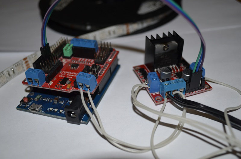
For implementation, you will need the Arduino Leonardo, L298N Motor Control Module, 12V Source (for powering the tape), the RGB tape itself, the connecting wires.
For ease of connection, I also used Fundruino IO Expansion, but it does not carry any functional load.
The wiring diagram is shown in the figure.
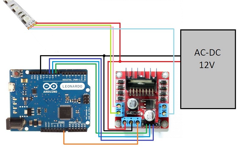
I want to further describe the power system. In this scheme, the power is supplied to the engine control module, there is a 5V reducing power supply in it, and I feed these 5V to the Vin input of the Arduino. If you break this connection (of course, leaving the earth connected), then you can power the Arduino and power switches from different power sources. This can be useful when a lot of things are connected to Arduino, and the source in the engine control module does not cope (it turns off by overheating).
It is controlled by the RGB tape using the analogWrite commands, which configures the output to form the PWM signal.
Source code for arduino:
In the video you can see how it works:
Total $ 37.65 = 1,300 rubles
For those who want to repeat the scheme described here - I want to note that the driver L298N is designed for a current of 2-3A per channel, and RGB LED strips on LED 5050 with a density of 60 LEDs per meter, sold for 5 meters, can consume up to 6A ( 2A per channel). Therefore, if you want to use tapes longer than 5M, you may need to upgrade the circuit (connect the tape in segments, or take a more powerful driver).
At this time, LED strips are available with a variable glow color. They look cool, are not expensive and can be well adapted for decorative interior lighting, advertising, etc.
These tapes can buy a power source, dimmer, dimmer with remote control. This will allow you to use the LED strip for illumination. However, if you want to program a color change algorithm, or make control from a computer, then disappointment begins. You will not find dimmers with control via COM-port or Ethernet.
')
I solved this problem with the help of Arduino, and I want to share my solution with you.
Welcome under cat.
Theoretical part
To implement a smooth change in the glow of all 3 channels, we need to make our own dimer. It is very simple to make it; it requires taking power keys and controlling them with the help of a PWM signal. Also our dimmer must be programmable and / or controlled from outside.
Arduino is ideally suited as brains. In its program, you can record any algorithm for changing colors, and it can also be controlled using Arduino modules or remotely via Ethernet, Ik-port, Bluetooth, using appropriate modules.
To implement my plan, I chose the Arduino Leonardo. It is one of the cheapest Arduino boards, and it has a lot of conclusions with PWM support.
PWM: 3, 5, 6, 9, 10, 11, and 13. Provide 8-bit PWM output with the analogWrite () function.
And so, we have a source of PWM, it remains to come up with power keys. If you wander on the internet shopping, it turns out that there is no Arduino module for managing RGB tapes. Or just universal modules with power transistors. You can also find a huge number of sites of radio amateurs who make boards with power switches themselves.
However, there is a simpler way! We are rescued by the Arduino module to control the engines. This module has everything you need - we have powerful 12V keys installed on it.
An example of such a module is the “L298N Module Dual H Bridge Stepper Motor Driver Modules for Arduino Smart Car FZ0407”. Such a module is based on the L298N microcircuit, which consists of 2 bridges. However, bridging is useful for the engine (from this it can change the direction of rotation), and in the case of an RGB tape, it is useless.
We will not use all the functionality of this microcircuit, but only 3 of its lower keys, connecting the tape as shown in the figure.
The practical part
For implementation, you will need the Arduino Leonardo, L298N Motor Control Module, 12V Source (for powering the tape), the RGB tape itself, the connecting wires.
For ease of connection, I also used Fundruino IO Expansion, but it does not carry any functional load.
The wiring diagram is shown in the figure.
I want to further describe the power system. In this scheme, the power is supplied to the engine control module, there is a 5V reducing power supply in it, and I feed these 5V to the Vin input of the Arduino. If you break this connection (of course, leaving the earth connected), then you can power the Arduino and power switches from different power sources. This can be useful when a lot of things are connected to Arduino, and the source in the engine control module does not cope (it turns off by overheating).
It is controlled by the RGB tape using the analogWrite commands, which configures the output to form the PWM signal.
Source code for arduino:
#define GRBLED_PIN_R 9 // R #define GRBLED_PIN_G 10 // G #define GRBLED_PIN_B 11 // B int rgbled_r=0, rgbled_g=0, rgbled_b=0; void setup(){ //enable serial datada print Serial.begin(9600); Serial.println("RBG LED v 0.1"); // RGBLED pinMode(GRBLED_PIN_R, OUTPUT); pinMode(GRBLED_PIN_G, OUTPUT); pinMode(GRBLED_PIN_B, OUTPUT); } void loop(){ // change color rgbled_r = (rgbled_r+1)%1024; rgbled_g = (rgbled_g+2)%1024; rgbled_b = (rgbled_b+3)%1024; // Output Z1_output_rgbled(); delay(1); } void Z1_output_rgbled() { analogWrite(GRBLED_PIN_R, rgbled_r); analogWrite(GRBLED_PIN_G, rgbled_g); analogWrite(GRBLED_PIN_B, rgbled_b); } In the video you can see how it works:
The economic part
| Module | Cost of | amount |
|---|---|---|
| L298N Module Dual Car Steering Motor Driver Board Modules for Arduino Smart Car FZ0407 | $ 5.31 | one |
| Leonardo R3 Development Board for Arduino Compatiblae + USB Cable Wire FZ0437 | $ 10.00 | one |
| 5050 LED Strip RGB and Single Color 5M DC12V / 24V 60leds / m | $ 12.38 | one |
| Retail AC85 ~ 265V to DC 12V / 6A power supply adapter transformer switching for led light | $ 9.98 | one |
Total $ 37.65 = 1,300 rubles
Instead of conclusion
For those who want to repeat the scheme described here - I want to note that the driver L298N is designed for a current of 2-3A per channel, and RGB LED strips on LED 5050 with a density of 60 LEDs per meter, sold for 5 meters, can consume up to 6A ( 2A per channel). Therefore, if you want to use tapes longer than 5M, you may need to upgrade the circuit (connect the tape in segments, or take a more powerful driver).
Source: https://habr.com/ru/post/224621/
All Articles