Wireless thermometer
... on ultra-cheap radio modules for $ 5 per bundle .

The kit contains a radio transmitter and superregenerative receiver. The number of contacts, in fact, 3 each, two of which are powered, hints at the extreme simplicity of working with them. True, the kit is more focused on remote control and is more often used in tandem with encoders and decoders on specialized chips, but we will miss it, because your bike is always more expensive.

Transmitter with amplitude modulation at a frequency of 433 MHz, the frequency is stabilized by SAW. The transmitter is a close relative of all one-, two-, three-transistor bugs and beacons, which made everyone who has ever been involved in radio engineering (a lot of circuits on vrtp.ru ). Power to the transmitter is allowed up to 12 V. Input data actually opens the transistor and starts the generation, with a low input level, the generation stops. Respectively exposing Hi and Lo at the input with a certain frequency, we can transfer data.
The receiver belongs to the class superregenerative. Today, this scheme is almost completely out of use and replaced by superheterodyne, but decades ago even industrial receivers were released to listen to the radio.
Supergenerate is the further development of a direct gain receiver. In the input circuit, due to positive feedback in the discontinuous mode, at frequencies of tens of kHz, the energy of the power source is introduced in the form of oscillations of the same frequency to which the circuit is tuned. This compensates for losses in the circuit and improves its Q-factor. At the output of the radio module there is a comparator issuing Data Hi or Lo to the line.
')

Advantages of superregenerative receivers:
The disadvantages arising from the advantages:
On both modules left a hole under the antenna. After the adjacent modules were finally separated, I realized that without an antenna there was nothing to do and I attached crocodiles with wires to the modules as antennas. In this form, the range of the collected devices was over 10 meters in a straight line when the transmitter was powered from the Krone 9V. I remind you that a piece of wire equal to approximately ¼ or ½ wavelength can be used as an antenna, in our case it will be 17 or 34 cm. It’s better to connect the common wire (GND) to the counterweight, which could be a metal case or another piece wires directed in the opposite direction from the antenna.
This picture is when you remove the transmitter by 10 meters. Despite the fact that the signal power is visually greatly reduced, the receiving module receives data confidently.
Now directly to the transfer of data. How naive I was when I connected the transmitter to the UART on one controller, and to the UART on the other. I saw a transmitted byte, although it was surrounded by dozens of extra! Look at the following picture, the receiver always catches something. And only when there is a steady periodic (!) Signal, it is clearly manifested in all incoming garbage. The UART transmits data one bit at a time, without dividing each bit, if 0x00 is transmitted, it will be a low level during the entire transfer of a byte, i.e. the transmitter will simply be turned off, and if 0xff is transmitted, this will be a high level, but even so, the receiver will soon begin to see discontinuities in it and give out a random sequence.
Those. I turn on the transmitter, soot the power data line, the transmitter broadcasts the carrier at full power, and at the receiver I see several units, and then garbage 11111111110100100101001. I release the data line, zeros appear and again 00000000011010101010. Conclusion: the receiver needs periodic level drops.
And we have this code. Mancunian. In the Manchester code, bits are encoded by a differential from a low level up (let it be 1), or from a top down (let it be 0). Accordingly, before the start of the transmission of each bit, the level should be set to the initial position, and in the middle should be changed. It has been experimentally found that the optimal data transfer rate is about 5-10-20 kilobits per second. This will allow to achieve a sufficiently stable reception, and will be used in the prototype of the device, which I will begin to describe further.
Traditionally it will be a thermometer, but now with wireless data transmission. According to the condition of the task on the bed under the film lies the transmitter, and in the house there is a receiver, which, as it were, collects the data from the sensors, well from one sensor, and builds a histogram. Those. if I see that at night there was 0 degrees, I understand from what all the seedlings are frozen and it remains only to find the culprit.
The transmitter is assembled on the controller Attiny13, with a thermal sensor LM335. Analog thermal sensor, gives 100mV to 1K. The reference voltage source MK uses an internal 1.1V. Since values from the sensor over 3V, then the data on the ADC is transmitted through a divider. The controller wakes up once every 30 minutes, and in debugging mode once every 4 seconds, it supplies power to the thermal sensor, turns on the transmitter, and for about 1-2 seconds transmits the current temperature a thousand times. Yes! It is a thousand times in a row, because even with 100 transmissions in a row, I skipped the data in some sessions. Modern cities, with dozens of automotive signaling at 433 MHz is not the most peaceful place.
The temperature is transmitted as a single byte with a Manchester coding.
0b10101011 on the receiver side turn into 21 ° .
Power is supplied through the same Krona 9V, measured by the Chinese tester in active mode consumption 6mA, in sleep mode 0,2mA. I can not pay attention to the voltage regulator circuit. The controller from 9V will simply die, and 5V or less will be small for the transmitter, so a power converter was needed. Boost pulse, perhaps I would interfere, and I did not experiment with it. It was easier to put a lowering linear, like the classic 7805. But suddenly I saw that she had her own consumption of 6 mA. This means that while the controller is sleeping, she will eat the entire battery. Googling, I found low-consuming converters LP2950, MCP1700…. But there weren't any nearby, but here such a circuit turned up on a pair of transistors 7002. Resistors had to be reduced not even to mega, but to hundreds of kilo, otherwise the output voltage did not rise above 3 with a small volt. Now it has become approximately 4.6V, which is quite comfortable for the controller.
The receiver is assembled on the basis of Attiny85 with a display from the Nokia 5110. The top line is reserved for the display of the current temperature, the bottom one shows the highest and the lowest. The central area 84x32 displays a histogram from 0 to 32C. Anything above or below is simply clipped.
Reception is ongoing. When switching to the receive line from Lo to Hi, an attempt is made to receive 8 data bits. In the original version, the reception of bits looked like this: The first transition from Lo to Hi is the middle of start bit 1, then the time is measured from it a little less than the bit duration, the value at the input is fixed, and a little later, when the time of the second half of the bit arrives, the value at the port is fixed again. This determines the transition to the upper or lower level. Further it is clear that it worked badly.
For screening garbage, I expect three parcels in a row, and if they match, then this will be the current temperature. At the same time, it is displayed for 0.5 sec. reception indicator is displayed. Once every 15 minutes, the histogram shifts, and if no new temperature is received within 45 minutes, the current temperature indication goes out, and the histogram will continue to move with an empty column. If the char in the GCC settings were not unsigned, then everything would have worked from half a kick, but strange glitches would peck out my brain until the night. And in the morning turning on the receiver, with the transmitter turned off, within half an hour I caught the noise, getting -91 degrees.
Then I did not lose my head and made an expectation of four parcels in a row. And I caught a false package again within half an hour. I did wait for two consecutive bytes and confirm their CRC8. And after an hour again I caught the false temperature, all according to the theorem on infinite monkeys.
“Half a dozen monkeys, if they had typewriters and one or other eternity in reserve, will create all the books that are kept today in the British Museum”
And, finally, having returned to the triple premise, but having changed the algorithm for receiving individual bits, I sort of calmed down, although I understand that the monkeys are not asleep.
In the modified algorithm, when each bit is received, several intermediate readings of the port are made, and if there is an untimely level transition, the reception is interrupted.
Despite the fact that these radio modules are hardly suitable for serious use as data transfer modules, but for collecting statistics, with the subsequent processing and rejection of obviously inaccurate data, it is quite.
Since the devices are only a demonstration function, then I deliberately do not spread the printed circuit boards, the more they should be repackaged to fix bugs.
The original krivoruky C-code and hex files in the archive . Fuse bits by default.
The kit contains a radio transmitter and superregenerative receiver. The number of contacts, in fact, 3 each, two of which are powered, hints at the extreme simplicity of working with them. True, the kit is more focused on remote control and is more often used in tandem with encoders and decoders on specialized chips, but we will miss it, because your bike is always more expensive.
Transmitter with amplitude modulation at a frequency of 433 MHz, the frequency is stabilized by SAW. The transmitter is a close relative of all one-, two-, three-transistor bugs and beacons, which made everyone who has ever been involved in radio engineering (a lot of circuits on vrtp.ru ). Power to the transmitter is allowed up to 12 V. Input data actually opens the transistor and starts the generation, with a low input level, the generation stops. Respectively exposing Hi and Lo at the input with a certain frequency, we can transfer data.
The receiver belongs to the class superregenerative. Today, this scheme is almost completely out of use and replaced by superheterodyne, but decades ago even industrial receivers were released to listen to the radio.
Supergenerate is the further development of a direct gain receiver. In the input circuit, due to positive feedback in the discontinuous mode, at frequencies of tens of kHz, the energy of the power source is introduced in the form of oscillations of the same frequency to which the circuit is tuned. This compensates for losses in the circuit and improves its Q-factor. At the output of the radio module there is a comparator issuing Data Hi or Lo to the line.
')
Advantages of superregenerative receivers:
- Simplicity and low cost designs
- Very high sensitivity
- High bandwidth
- Automatic gain control
The disadvantages arising from the advantages:
- Wide bandwidth, which always gets something. The value of the order of units is MHz.
- High sensitivity, even though the transmitter is on, even off, there is always some noise at the receiver output (see below).
- The difficulty in setting up, because the superregenerative cascade simultaneously performs two or three functions (amplifier, generator, detector). But we already have nothing to set up.
On both modules left a hole under the antenna. After the adjacent modules were finally separated, I realized that without an antenna there was nothing to do and I attached crocodiles with wires to the modules as antennas. In this form, the range of the collected devices was over 10 meters in a straight line when the transmitter was powered from the Krone 9V. I remind you that a piece of wire equal to approximately ¼ or ½ wavelength can be used as an antenna, in our case it will be 17 or 34 cm. It’s better to connect the common wire (GND) to the counterweight, which could be a metal case or another piece wires directed in the opposite direction from the antenna.
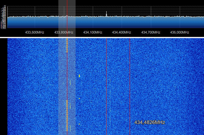
This picture is when you remove the transmitter by 10 meters. Despite the fact that the signal power is visually greatly reduced, the receiving module receives data confidently.
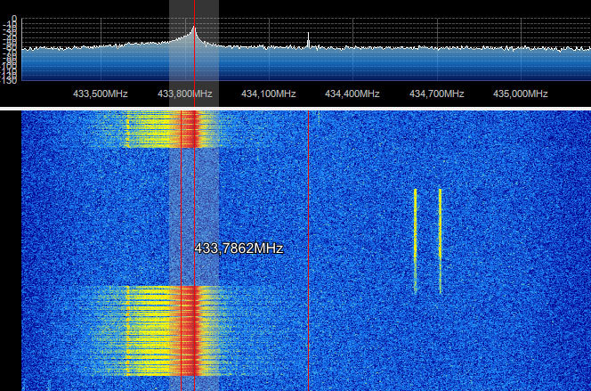
Now directly to the transfer of data. How naive I was when I connected the transmitter to the UART on one controller, and to the UART on the other. I saw a transmitted byte, although it was surrounded by dozens of extra! Look at the following picture, the receiver always catches something. And only when there is a steady periodic (!) Signal, it is clearly manifested in all incoming garbage. The UART transmits data one bit at a time, without dividing each bit, if 0x00 is transmitted, it will be a low level during the entire transfer of a byte, i.e. the transmitter will simply be turned off, and if 0xff is transmitted, this will be a high level, but even so, the receiver will soon begin to see discontinuities in it and give out a random sequence.
Those. I turn on the transmitter, soot the power data line, the transmitter broadcasts the carrier at full power, and at the receiver I see several units, and then garbage 11111111110100100101001. I release the data line, zeros appear and again 00000000011010101010. Conclusion: the receiver needs periodic level drops.
And we have this code. Mancunian. In the Manchester code, bits are encoded by a differential from a low level up (let it be 1), or from a top down (let it be 0). Accordingly, before the start of the transmission of each bit, the level should be set to the initial position, and in the middle should be changed. It has been experimentally found that the optimal data transfer rate is about 5-10-20 kilobits per second. This will allow to achieve a sufficiently stable reception, and will be used in the prototype of the device, which I will begin to describe further.
Traditionally it will be a thermometer, but now with wireless data transmission. According to the condition of the task on the bed under the film lies the transmitter, and in the house there is a receiver, which, as it were, collects the data from the sensors, well from one sensor, and builds a histogram. Those. if I see that at night there was 0 degrees, I understand from what all the seedlings are frozen and it remains only to find the culprit.
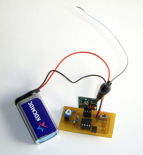
The transmitter is assembled on the controller Attiny13, with a thermal sensor LM335. Analog thermal sensor, gives 100mV to 1K. The reference voltage source MK uses an internal 1.1V. Since values from the sensor over 3V, then the data on the ADC is transmitted through a divider. The controller wakes up once every 30 minutes, and in debugging mode once every 4 seconds, it supplies power to the thermal sensor, turns on the transmitter, and for about 1-2 seconds transmits the current temperature a thousand times. Yes! It is a thousand times in a row, because even with 100 transmissions in a row, I skipped the data in some sessions. Modern cities, with dozens of automotive signaling at 433 MHz is not the most peaceful place.
The temperature is transmitted as a single byte with a Manchester coding.
0b10101011 on the receiver side turn into 21 ° .
Transfer bytes
void send1() { PORT_TX&=~B_TX; _delay_us(DELAY_US); PORT_TX|=B_TX; _delay_us(DELAY_US); } void send0() { PORT_TX|=B_TX; _delay_us(DELAY_US); PORT_TX&=~B_TX; _delay_us(DELAY_US); } void send(char c) { send1(); for(uint8_t i=128; i>0; i>>=1) { if(c & i) send1(); else send0(); } PORT_TX&=~B_TX; } Falling asleep after data transfer until interrupt from watchdog timer
if(debug_mode) { cli(); wdt_reset(); WDTCR=1<<WDCE | 1<<WDTIE; WDTCR=1<<WDP3 | 1<<WDTIE; // 4 sei(); MCUCR|=1<<SE | 1<<SM1; // Power-down sleep_cpu(); } else for(uint8_t i=0; i<SLEEP_TIME; i++) { cli(); wdt_reset(); WDTCR=1<<WDCE | 1<<WDTIE; WDTCR=1<<WDP3 | 1<<WDP0 | 1<<WDTIE; // 8 sei(); MCUCR|=1<<SE | 1<<SM1; sleep_cpu(); } Power is supplied through the same Krona 9V, measured by the Chinese tester in active mode consumption 6mA, in sleep mode 0,2mA. I can not pay attention to the voltage regulator circuit. The controller from 9V will simply die, and 5V or less will be small for the transmitter, so a power converter was needed. Boost pulse, perhaps I would interfere, and I did not experiment with it. It was easier to put a lowering linear, like the classic 7805. But suddenly I saw that she had her own consumption of 6 mA. This means that while the controller is sleeping, she will eat the entire battery. Googling, I found low-consuming converters LP2950, MCP1700…. But there weren't any nearby, but here such a circuit turned up on a pair of transistors 7002. Resistors had to be reduced not even to mega, but to hundreds of kilo, otherwise the output voltage did not rise above 3 with a small volt. Now it has become approximately 4.6V, which is quite comfortable for the controller.
The scheme of the transmitter, how not to do!
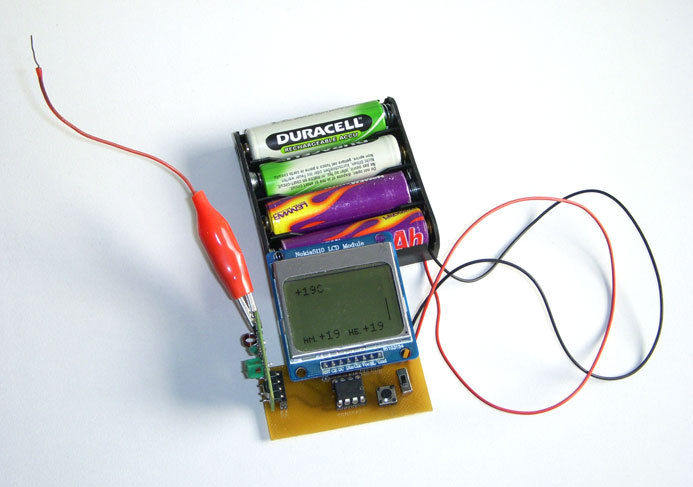
The receiver is assembled on the basis of Attiny85 with a display from the Nokia 5110. The top line is reserved for the display of the current temperature, the bottom one shows the highest and the lowest. The central area 84x32 displays a histogram from 0 to 32C. Anything above or below is simply clipped.
Reception is ongoing. When switching to the receive line from Lo to Hi, an attempt is made to receive 8 data bits. In the original version, the reception of bits looked like this: The first transition from Lo to Hi is the middle of start bit 1, then the time is measured from it a little less than the bit duration, the value at the input is fixed, and a little later, when the time of the second half of the bit arrives, the value at the port is fixed again. This determines the transition to the upper or lower level. Further it is clear that it worked badly.
Receiver circuit
For screening garbage, I expect three parcels in a row, and if they match, then this will be the current temperature. At the same time, it is displayed for 0.5 sec. reception indicator is displayed. Once every 15 minutes, the histogram shifts, and if no new temperature is received within 45 minutes, the current temperature indication goes out, and the histogram will continue to move with an empty column. If the char in the GCC settings were not unsigned, then everything would have worked from half a kick, but strange glitches would peck out my brain until the night. And in the morning turning on the receiver, with the transmitter turned off, within half an hour I caught the noise, getting -91 degrees.
Then I did not lose my head and made an expectation of four parcels in a row. And I caught a false package again within half an hour. I did wait for two consecutive bytes and confirm their CRC8. And after an hour again I caught the false temperature, all according to the theorem on infinite monkeys.
“Half a dozen monkeys, if they had typewriters and one or other eternity in reserve, will create all the books that are kept today in the British Museum”
And, finally, having returned to the triple premise, but having changed the algorithm for receiving individual bits, I sort of calmed down, although I understand that the monkeys are not asleep.
In the modified algorithm, when each bit is received, several intermediate readings of the port are made, and if there is an untimely level transition, the reception is interrupted.
It was
int8_t read_bit() { _delay_us(160); // char rx=PIN_RX & B_RX; // for(uint8_t i=0; i<6; i++) { if((PIN_RX & B_RX) != rx) { if(rx) return 0; else return 1; } } return -1; } It became
int8_t read_bit() { char rx=PIN_RX & B_RX; for(uint8_t i=0; i<5; i++) { if((PIN_RX & B_RX) != rx) return -1; // } _delay_us(40); // rx=PIN_RX & B_RX; for(uint8_t i=0; i<5; i++) { if((PIN_RX & B_RX) != rx) return -1; // } rx=PIN_RX & B_RX; for(uint8_t i=0; i<6; i++) // { if((PIN_RX & B_RX) != rx) { if(rx) return 0; else return 1; } } return -1; } Despite the fact that these radio modules are hardly suitable for serious use as data transfer modules, but for collecting statistics, with the subsequent processing and rejection of obviously inaccurate data, it is quite.
Since the devices are only a demonstration function, then I deliberately do not spread the printed circuit boards, the more they should be repackaged to fix bugs.
The original krivoruky C-code and hex files in the archive . Fuse bits by default.
Source: https://habr.com/ru/post/224459/
All Articles