Doing Smart Point or “Internet thing” with your own hands
In this article I will describe the concept and example of the practical implementation of a compact platform for creating solutions in the field of home automation and the Internet of Things.
Interested please under the cat.
')
Recently, there has been a pronounced tendency of growing interest in such an area of information technology as the automation of vital activity. Automation in itself is not a new phenomenon and for decades the majority of industrial production is not a whim, but a necessity, without which business survival in the face of fierce competition is unthinkable. So why just now we hear so much about the Internet of Things, M2M (Machine-to-machine) communications and other “smart” technologies? Perhaps the reason is that, as in many similar cases, some “critical mass” of innovation was accumulated along with the availability of the element base for the general public. Just as the development of the Internet and the availability of Internet technologies once gave rise to a whole wave of information projects that are changing the world so far, now we are witnessing how many such building blocks as programming, microelectronics, the Internet creates interesting household solutions. Not all of them will “fly up” and this is absolutely normal, but many of them can be the basis (or inspiration) for something truly amazing.
Personally, I have been very actively interested in this for more than a year, and perhaps some have heard about the open project of the Major DoMo Smart House, which I have the pleasure to create and work on. But now it's not about him, but about some parallel project, another experiment, if you like, which I was fascinated with some time ago and the results of which I share in this article.
Having in the “baggage” project of the Smart Home platform, I thought that although it is very flexible in use, but a large number of possibilities require appropriate equipment, which is not always convenient and practical. For some tasks, “small” automation can be managed with one microcontroller, but here we are already losing flexibility and raising demands on the user's qualifications. It seemed obvious to me that there is a need for some intermediate version - quite compact and energy-efficient, but at the same time flexible in configuration and use. We give the working title to this option “Smart Point” or SmartPoint. Along the way, a whole wish list has been formed on the possibilities that it would be great to receive in this device.
So, from the lyrics to the practice. Here are the basic requirements for a SmartPoint device:
Additional (practical) wishes for the device:
Pondering over and over the concept, as well as a considerable set of “Wishlist”, came to the conclusion that it would not be possible to manage with one microcontroller. First of all, I still don’t know how to program them so well that I can realize everything that was planned at a low level, and secondly, not every controller will make such an appetite of wishes. It was decided to follow the path of least resistance - to divide the device into two logical parts: one (“controller”) will be based on a microcontroller and responsible for elementary interaction with “hardware”, and the second (“host”) based on embedded Linux, be responsible for more high level (interface, rule system, API). The Arduino microcontroller was selected as the first unit (guess!), And the TP-Link WR703N router with OpenWRT firmware went into operation as the second unit (note: a pair of similar devices were successfully assembled on the DLink Dir-320 router). Anticipating righteous anger, I hasten to remind you that our task is first of all to check the viability of the concept on a prototype, and not to design and assemble a commercial device. In addition, the use of these components facilitates the repetition of the device - long live open-source! Using the same Arduino allows you to apply the experience of connecting an infinite variety of sensors and actuating modules to our device.
TP-Link WR703N router:

Arduino Nano microcontroller:
The following elements were chosen as the initial set of peripherals:
The set of peripherals, as you understand, may be different, but in this example I took this one on the basis of the principle of “practical utility” mentioned above. Thus, our device will be able to respond to pressing the button, to movement, to temperature changes, as well as to receive data from external sensors (in this case, the protocol described earlier in the Habré protocol was used) and to control the power modules of the Noolite system (a separate history control module and the photograph is not a commercial copy of the module, but one of the earliest prototypes from the manufacturer that came to me for testing).
Combining the sketches for the implementation and the initial requirements, we obtain the following block diagram of the device:
Explanation of the scheme:
The microcontroller has two main tasks: first, to issue events from external devices to the console, and, second, to receive commands from the console for transmission to the connected peripherals.
Below is the text of the sketch, taking into account the specifics of the above-listed periphery. In our case, the button is connected to PIN4, a motion sensor on PIN3, a temperature sensor on PIN9, a radio receiver on PIN8, and a Noolite module on PINs 10, 11.
The controller’s operation with peripherals can be checked without connecting it to the host module, but simply start the port monitor after the firmware and see what is output to the console. It is this data flow that the host module will receive, but it will still be able to respond to it in accordance with the established rules.
I will not dwell on the firmware of the router with the OpenWRT system and the subsequent configuration in the framework of this article. As a result, we should have a router in the client mode of the local WiFi-network with Internet access, as well as correctly determining the connected microcontroller as a COM port.
The next step is to transform our router into a host module. I used the Bash interpreter to write host module scripts, since It seemed to me quite convenient and versatile, i.e. not binding the host module platform to any particular “hardware” implementation — instead of a router with OpenWRT, there can be any device with a built-in Linux, if only there is Bash and drivers for connecting the microcontroller.
The algorithm of the host module can be represented by the following points:
At the source code level, it looks like this:
In the settings you can see that the device has a unique identifier (MASTER_ID), which is used to interact with the web service (recall that the presence of a permanent connection with it is not necessary).
During the operation of the main script, the / etc / master / data / directory is used to store the loaded code of the rules, the values of the last sensor readings, as well as for the operation of some structures of the rule system (for example, timers).
A complete set of files can be downloaded from this link .
The rule system was outlined above, so I’ll dwell on it a bit more in detail. In fact, each rule is a set of bash instructions. The first part of this set, let's call it Activator, checks the incoming data for compliance with this rule, and the second part (the Contractor) directly performs some actions.
Possible conditions for activating the rule:
Possible actions:
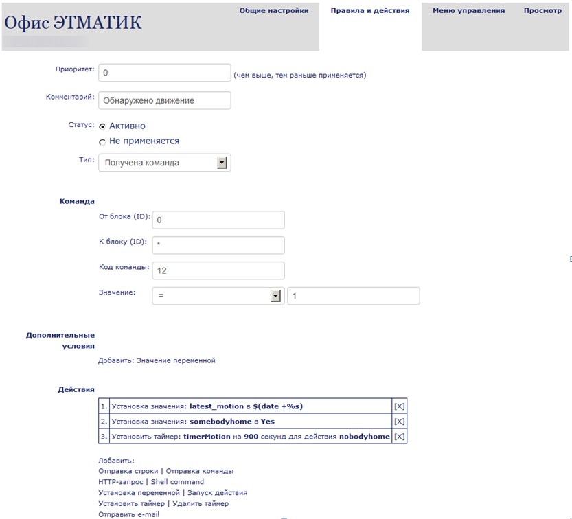
The rules are configured through the user's personal account after the device is registered in the web system (now the entire server component is implemented as part of the connect.smartliving.ru project). There is no need to program it, the web system itself converts user-defined rules into bash commands. From the user's side, the configuration interface looks like this:
In principle, the above is quite enough to create a standalone module, however, the wish list was long, as was the path to implementation. The next step was to create a web interface and API. This step is not complicated enough, as compared with the previous ones, and it was implemented by a similar principle. There is already a web server on the host device, so another bash script was created to implement the API and placed in / www / cgi-bin / master
This script provides the following API commands:
Setting the variable value
Sets the value of variable Variable1 to Value1
Getting variable value
Returns the value of the variable Variable1
Sending data to the controller
Sends the SomeData line to the connected controller
Activation action
Initializes the action SomeAction, described in the rules (type "Active actions")
Force update rules
Initializes a forced update (download) of the rules and the web interface without rebooting the device
System command
Initializes SomeCommand execution in the system shell (for example, using "reboot" will restart the device)
After the API was a web interface. It was treated the same way as with the rules - we configure it on the web service and update it on the device at the same initialization stage. Here is the interface for creating the control menu for the device:
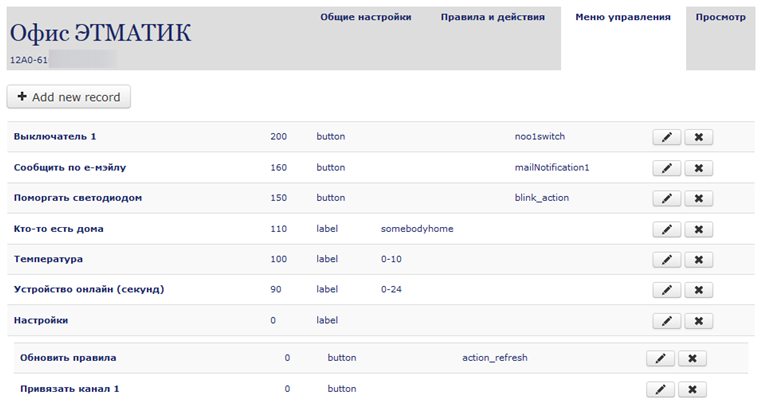
In order not to reinvent the wheel, the Kraken lightweight frontend framework was taken and thrown into the / www / kraken-master folder. After initialization, the menu.html file appears in the / www / folder and, accordingly, you can access our customized web interface at
“Uh, well, the sistemka turns out and it's not all?” - you ask. Well, almost, it remains just a little. More precisely, "a little" for the user, but a big stage for the developer (as often happens). Namely - work with the device via the Internet. It would seem that there is a web interface, send ports on the router and enjoy your health. But these are not our methods, our methods in simplifying the lives of others (and complicating ourselves). Suppose the worst - there is no possibility to change the settings of the router and make forward ports. Or it is intended to use a variety of similar devices on the same network and each (hypothetically) wants to be able to access from the outside. The solution was such - the device itself should initiate and maintain a channel with an external server for exchanging data and commands, while the external server duplicated the web interface specified for a specific device and organized the transmission of commands from the user through this channel. The channel is a socket-connection, which on the one hand (on the device) creates a separate bash-script and on the other hand (on the server) a socket-server.
On the device, the script is in / etc / master / socket_client
The user from his account has a link and a QR code for working with the device. One of the test examples below:

All the described construction works quite stably - from the moment of launch and the time I decided to write an article, perhaps a couple of months have passed, and the device regularly performs its functions. However, everything is implemented, as they say, without excesses. To test the concept, this is enough, but for mass implementation of devices on this (or similar) platform, I would work in the following areas:
The article does not describe all the details of the settings and some things such as the settings for autorun scripts, I deliberately omitted, trying to convey the basic features and essence of the concept.
Specifically, this device and the whole process of its creation was an experiment to test the operation of individual components and technologies. In the process, ideas appeared in other devices and systems, and something migrated from outside to this project, so that, in general, time was spent for nothing. I would be glad if my implementation experience would be useful.
If we develop the topic of commercial application of the concept, then we can talk about less universal, but, rather, applied implementations. For example:
Thus, having the same base, you can create many applied “boxed” solutions, integrating such “Internet things” with information systems at a higher level.
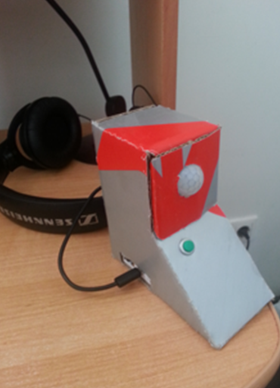
PS I thought for a long time whether to post a “live” photo of the resulting device, but I already warned about the experimental nature of the whole project, so the cardboard case (or its layout, if you like) is quite consistent:
PPS I almost forgot, the cost of this device with all the listed components is about $ 60, the time spent is priceless.
Interested please under the cat.
')
Instead of introducing
Recently, there has been a pronounced tendency of growing interest in such an area of information technology as the automation of vital activity. Automation in itself is not a new phenomenon and for decades the majority of industrial production is not a whim, but a necessity, without which business survival in the face of fierce competition is unthinkable. So why just now we hear so much about the Internet of Things, M2M (Machine-to-machine) communications and other “smart” technologies? Perhaps the reason is that, as in many similar cases, some “critical mass” of innovation was accumulated along with the availability of the element base for the general public. Just as the development of the Internet and the availability of Internet technologies once gave rise to a whole wave of information projects that are changing the world so far, now we are witnessing how many such building blocks as programming, microelectronics, the Internet creates interesting household solutions. Not all of them will “fly up” and this is absolutely normal, but many of them can be the basis (or inspiration) for something truly amazing.
Personally, I have been very actively interested in this for more than a year, and perhaps some have heard about the open project of the Major DoMo Smart House, which I have the pleasure to create and work on. But now it's not about him, but about some parallel project, another experiment, if you like, which I was fascinated with some time ago and the results of which I share in this article.
Having in the “baggage” project of the Smart Home platform, I thought that although it is very flexible in use, but a large number of possibilities require appropriate equipment, which is not always convenient and practical. For some tasks, “small” automation can be managed with one microcontroller, but here we are already losing flexibility and raising demands on the user's qualifications. It seemed obvious to me that there is a need for some intermediate version - quite compact and energy-efficient, but at the same time flexible in configuration and use. We give the working title to this option “Smart Point” or SmartPoint. Along the way, a whole wish list has been formed on the possibilities that it would be great to receive in this device.
Task
So, from the lyrics to the practice. Here are the basic requirements for a SmartPoint device:
- Flexible rules for responding to events from sensors
- Web interface for “manual” control
- HTTP API for integration into a more complex complex
- Work ONLINE - access to the web interface of the device via the Internet without static IP and “forwarding” of ports on the router
- Work OFFLINE - the functioning of the configured device should not depend on the availability of Internet access
Additional (practical) wishes for the device:
- Work on wifi
- The presence of built-in sensors and executive modules (the device should be of practical use immediately “out of the box” and not “in theory”)
- Wireless “local” interface for interfacing with simpler sensors / actuating modules
- Internet service (personal account) for setting up and monitoring the operation of the device
Controller, host, peripherals
Pondering over and over the concept, as well as a considerable set of “Wishlist”, came to the conclusion that it would not be possible to manage with one microcontroller. First of all, I still don’t know how to program them so well that I can realize everything that was planned at a low level, and secondly, not every controller will make such an appetite of wishes. It was decided to follow the path of least resistance - to divide the device into two logical parts: one (“controller”) will be based on a microcontroller and responsible for elementary interaction with “hardware”, and the second (“host”) based on embedded Linux, be responsible for more high level (interface, rule system, API). The Arduino microcontroller was selected as the first unit (guess!), And the TP-Link WR703N router with OpenWRT firmware went into operation as the second unit (note: a pair of similar devices were successfully assembled on the DLink Dir-320 router). Anticipating righteous anger, I hasten to remind you that our task is first of all to check the viability of the concept on a prototype, and not to design and assemble a commercial device. In addition, the use of these components facilitates the repetition of the device - long live open-source! Using the same Arduino allows you to apply the experience of connecting an infinite variety of sensors and actuating modules to our device.
TP-Link WR703N router:
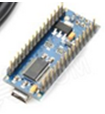
Arduino Nano microcontroller:
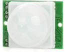
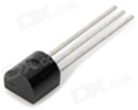
The following elements were chosen as the initial set of peripherals:
- Button

- Motion Sensor
- DS18B20 temperature sensor
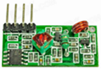
- 433Mhz receiver
- Noolite Light Control Transmitter

The set of peripherals, as you understand, may be different, but in this example I took this one on the basis of the principle of “practical utility” mentioned above. Thus, our device will be able to respond to pressing the button, to movement, to temperature changes, as well as to receive data from external sensors (in this case, the protocol described earlier in the Habré protocol was used) and to control the power modules of the Noolite system (a separate history control module and the photograph is not a commercial copy of the module, but one of the earliest prototypes from the manufacturer that came to me for testing).
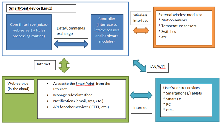
Combining the sketches for the implementation and the initial requirements, we obtain the following block diagram of the device:
Explanation of the scheme:
- The device consists of a microcontroller that interacts with wired / wireless peripherals, and a core responsible for the logic of processing incoming data and interfaces
- There is an API and a web interface for receiving commands from external "terminals" (computers, phones, etc.)
- Communicating with an external service to download rules, send notifications and receive commands
Microcontroller preparation
The microcontroller has two main tasks: first, to issue events from external devices to the console, and, second, to receive commands from the console for transmission to the connected peripherals.
Below is the text of the sketch, taking into account the specifics of the above-listed periphery. In our case, the button is connected to PIN4, a motion sensor on PIN3, a temperature sensor on PIN9, a radio receiver on PIN8, and a Noolite module on PINs 10, 11.
Sketch for the controller
#include <OneWire.h> #include <DallasTemperature.h> #include <VirtualWire.h> #include <EasyTransferVirtualWire.h> #include <EEPROM.h> //Needed to access the eeprom read write functions #include <SoftwareSerial.h> #define PIN_LED (13) // INDICATOR #define PIN_PIR (3) // BUTTON #define PIN_BUTTON (4) // BUTTON #define PIN_LED_R (6) // INDICATOR RED #define PIN_LED_G (5) // INDICATOR GREEN #define PIN_LED_B (7) // INDICATOR BLUE #define PIN_RF_RECEIVE (8) // EASYRF RECEIVER #define PIN_TEMP (9) // TEMPERATURE SENSOR #define PIN_NOO_RX (10) // RX PIN (connect to TX on noolite controller) #define PIN_NOO_TX (11) // TX PIN (connect to RX on noolite controller) #define TEMP_ACC (0.3) // temperature accuracy #define PERIOD_READ_TEMP (20) // seconds #define PERIOD_SEND_TEMP (600) // seconds (10 minutes) #define PERIOD_SEND_UPTIME (300) // seconds (5 minutes) #define NOO_BUF_LEN (12) unsigned int unique_device_id = 0; long int uptime = 0; long int old_uptime = 0; float sent_temperature=0; int sent_pir=0; int sent_button=0; int sent_button_longlick=0; long int timeCheckedTemp=0; long int timeSentTemp=0; long int timeSentUptime=0; long int timeButtonPressed=0; String inData; //create objects SoftwareSerial mySerial(PIN_NOO_RX, PIN_NOO_TX); // RX, TX OneWire oneWire(PIN_TEMP); DallasTemperature sensors(&oneWire); EasyTransferVirtualWire ET; unsigned int last_packet_id = 0; struct SEND_DATA_STRUCTURE{ //put your variable definitions here for the data you want to send //THIS MUST BE EXACTLY THE SAME ON THE OTHER ARDUINO //Struct can'e be bigger then 26 bytes for VirtualWire version unsigned int device_id; unsigned int destination_id; unsigned int packet_id; byte command; int data; }; //give a name to the group of data SEND_DATA_STRUCTURE mydata; //This function will write a 2 byte integer to the eeprom at the specified address and address + 1 void EEPROMWriteInt(int p_address, unsigned int p_value) { byte lowByte = ((p_value >> 0) & 0xFF); byte highByte = ((p_value >> 8) & 0xFF); EEPROM.write(p_address, lowByte); EEPROM.write(p_address + 1, highByte); } //This function will read a 2 byte integer from the eeprom at the specified address and address + 1 unsigned int EEPROMReadInt(int p_address) { byte lowByte = EEPROM.read(p_address); byte highByte = EEPROM.read(p_address + 1); return ((lowByte << 0) & 0xFF) + ((highByte << 8) & 0xFF00); } void nooSend(byte channel, byte buf[NOO_BUF_LEN]) { buf[0]=85; buf[1]=B01010000; // buf[4]=0; buf[5]=channel; buf[9]=0; int checkSum; for(byte i=0;i<(NOO_BUF_LEN-2);i++) { checkSum+=buf[i]; } buf[10]=lowByte(checkSum); buf[11]=170; Serial.print("Sending: "); for(byte i=0;i<(NOO_BUF_LEN);i++) { Serial.print(buf[i]); if (i!=(NOO_BUF_LEN-1)) { Serial.print('-'); } } Serial.println(""); for(byte i=0;i<(NOO_BUF_LEN);i++) { mySerial.write(buf[i]); } } void noolitePair(byte channel) { byte buf[NOO_BUF_LEN]; for(byte i=0;i<(NOO_BUF_LEN);i++) { buf[i]=0; } buf[2]=15; buf[3]=0; nooSend(channel,buf); } void nooliteUnPair(byte channel) { byte buf[NOO_BUF_LEN]; for(byte i=0;i<(NOO_BUF_LEN);i++) { buf[i]=0; } buf[2]=9; buf[3]=0; nooSend(channel,buf); } void nooliteTurnOn(byte channel) { byte buf[NOO_BUF_LEN]; for(byte i=0;i<(NOO_BUF_LEN);i++) { buf[i]=0; } buf[2]=2; buf[3]=0; nooSend(channel,buf); } void nooliteTurnOff(byte channel) { byte buf[NOO_BUF_LEN]; for(byte i=0;i<(NOO_BUF_LEN);i++) { buf[i]=0; } buf[2]=0; buf[3]=0; nooSend(channel,buf); } void nooliteSwitch(byte channel) { byte buf[NOO_BUF_LEN]; for(byte i=0;i<(NOO_BUF_LEN);i++) { buf[i]=0; } buf[2]=4; buf[3]=0; nooSend(channel,buf); } void nooliteLevel(byte channel,byte level) { byte buf[NOO_BUF_LEN]; for(byte i=0;i<(NOO_BUF_LEN);i++) { buf[i]=0; } buf[2]=6; buf[3]=1; buf[6]=level; nooSend(channel,buf); } void blinking(int count) { for(int i=0;i<count;i++) { digitalWrite(PIN_LED, HIGH); delay(200); digitalWrite(PIN_LED, LOW); delay(200); } } void setColor(int r,int g, int b) { digitalWrite(PIN_LED_R, r); digitalWrite(PIN_LED_G, g); digitalWrite(PIN_LED_B, b); } void setup() { randomSeed(analogRead(0)); pinMode(PIN_LED, OUTPUT); pinMode(PIN_LED_R, OUTPUT); pinMode(PIN_LED_G, OUTPUT); pinMode(PIN_LED_B, OUTPUT); pinMode(PIN_PIR, INPUT); pinMode(PIN_BUTTON, INPUT); Serial.begin(9600); // Debugging only ET.begin(details(mydata)); // Initialise the IO and ISR vw_set_rx_pin(PIN_RF_RECEIVE); vw_setup(2000); // Bits per sec vw_rx_start(); // Start the receiver PLL running // Device ID Serial.print("Getting Device ID... "); unique_device_id=EEPROMReadInt(0); if (unique_device_id<10000 || unique_device_id>60000 || unique_device_id==26807) { Serial.print("N/A, updating... "); unique_device_id=random(10000, 60000); EEPROMWriteInt(0, unique_device_id); } Serial.println(unique_device_id); pinMode(PIN_NOO_RX, INPUT); pinMode(PIN_NOO_TX, OUTPUT); mySerial.begin(9600); } void loop() { uptime=round(millis()/1000); if (uptime!=old_uptime) { Serial.print("Up: "); Serial.println(uptime); old_uptime=uptime; if (((uptime-timeSentUptime)>PERIOD_SEND_UPTIME) || (timeSentUptime>uptime)) { timeSentUptime=uptime; Serial.print("P:"); Serial.print(random(65535)); Serial.print(";F:"); Serial.print("0"); Serial.print(";T:0;C:"); Serial.print("24"); Serial.print(";D:"); Serial.print(uptime); Serial.println(";"); } } int current_pir=digitalRead(PIN_PIR); if (current_pir!=sent_pir) { Serial.print(millis()/1000); Serial.print(" Motion sensor: "); Serial.println(current_pir); Serial.print("P:"); Serial.print(random(65535)); Serial.print(";F:"); Serial.print("0"); Serial.print(";T:0;C:"); Serial.print("12"); Serial.print(";D:"); Serial.print("1"); Serial.println(";"); sent_pir=(int)current_pir; } int current_button=digitalRead(PIN_BUTTON); if (current_button!=sent_button) { delay(50); int confirm_current_button=digitalRead(PIN_BUTTON); if (confirm_current_button==current_button) { if (current_button==1) { timeButtonPressed=millis(); sent_button_longlick=0; } if (current_button==0) { if (sent_button_longlick!=1) { Serial.print(millis()/1000); Serial.print(" Button press: "); Serial.println(current_button); Serial.print("P:"); Serial.print(random(65535)); Serial.print(";F:"); Serial.print("0"); Serial.print(";T:0;C:"); Serial.print("23"); Serial.print(";D:"); Serial.print("3"); Serial.println(";"); } } sent_button=(int)current_button; } } else { if (current_button==1) { int passed=millis()-timeButtonPressed; if ((passed>3000) && (sent_button_longlick!=1)) { sent_button_longlick=1; Serial.print(millis()/1000); Serial.print(" Button long press: "); Serial.println(current_button); Serial.print("P:"); Serial.print(random(65535)); Serial.print(";F:"); Serial.print("0"); Serial.print(";T:0;C:"); Serial.print("23"); Serial.print(";D:"); Serial.print("4"); Serial.println(";"); } } else { sent_button_longlick=0; } } if (((uptime-timeCheckedTemp)>PERIOD_READ_TEMP) || (timeCheckedTemp>uptime)) { // TEMP SENSOR 1 float current_temp=0; sensors.requestTemperatures(); current_temp=sensors.getTempCByIndex(0); if (current_temp>-100 && current_temp<50) { timeCheckedTemp=uptime; Serial.print("Temp sensor: "); Serial.println(current_temp); float diff=(float)sent_temperature-(float)current_temp; if ((abs(diff)>=TEMP_ACC) || ((uptime-timeSentTemp)>PERIOD_SEND_TEMP)) { // timeSentTemp=uptime; sent_temperature=(float)current_temp; Serial.print("P:"); Serial.print(random(65535)); Serial.print(";F:"); Serial.print("0"); Serial.print(";T:0;C:"); Serial.print("10"); Serial.print(";D:"); Serial.print((int)(current_temp*100)); Serial.println(";"); } } else { //Serial.print("Incorrect T: "); //Serial.println(current_temp); } } if (Serial.available()) { char c=Serial.read(); if (c == '\n' || c == ';') { Serial.println(inData); int commandProcessed=0; if (inData.equals("blink")) { Serial.println("BLINKING!"); blinking(3); commandProcessed=1; } if (inData.startsWith("pair")) { commandProcessed=1; inData.replace("pair",""); noolitePair(inData.toInt()); } if (inData.startsWith("on")) { commandProcessed=1; inData.replace("on",""); nooliteTurnOn(inData.toInt()); } if (inData.startsWith("off")) { commandProcessed=1; inData.replace("off",""); nooliteTurnOff(inData.toInt()); } if (inData.startsWith("switch")) { commandProcessed=1; inData.replace("switch",""); nooliteSwitch(inData.toInt()); } if (inData.startsWith("level")) { commandProcessed=1; inData.replace("level",""); int splitPosition; splitPosition=inData.indexOf('-'); if(splitPosition != -1) { String paramString=inData.substring(0,splitPosition); int channel=paramString.toInt(); inData=inData.substring(splitPosition+1,inData.length()); nooliteLevel(channel,inData.toInt()); } } if (inData.startsWith("unpair")) { commandProcessed=1; inData.replace("unpair",""); nooliteUnPair(inData.toInt()); } if (inData.startsWith("color-")) { commandProcessed=1; inData.replace("color-",""); if (inData.equalsIgnoreCase("r")) { setColor(255,0,0); } if (inData.equalsIgnoreCase("g")) { setColor(0,255,0); } if (inData.equalsIgnoreCase("b")) { setColor(0,0,255); } if (inData.equalsIgnoreCase("w")) { setColor(255,255,255); } if (inData.equalsIgnoreCase("off")) { setColor(0,0,0); } } if (commandProcessed==0) { Serial.print("Unknown command: "); Serial.println(inData); } inData=""; Serial.flush(); } else { inData += (c); } } if(ET.receiveData()) { digitalWrite(PIN_LED, HIGH); if (last_packet_id!=(int)mydata.packet_id) { Serial.print("P:"); Serial.print(mydata.packet_id); Serial.print(";F:"); Serial.print(mydata.device_id); Serial.print(";T:"); Serial.print(mydata.destination_id); Serial.print(";C:"); Serial.print(mydata.command); Serial.print(";D:"); Serial.print(mydata.data); Serial.println(";"); last_packet_id=(int)mydata.packet_id; } digitalWrite(PIN_LED, LOW); } if (mySerial.available()) Serial.write(mySerial.read()); } The controller’s operation with peripherals can be checked without connecting it to the host module, but simply start the port monitor after the firmware and see what is output to the console. It is this data flow that the host module will receive, but it will still be able to respond to it in accordance with the established rules.
Preparing the host module (router)
I will not dwell on the firmware of the router with the OpenWRT system and the subsequent configuration in the framework of this article. As a result, we should have a router in the client mode of the local WiFi-network with Internet access, as well as correctly determining the connected microcontroller as a COM port.
The next step is to transform our router into a host module. I used the Bash interpreter to write host module scripts, since It seemed to me quite convenient and versatile, i.e. not binding the host module platform to any particular “hardware” implementation — instead of a router with OpenWRT, there can be any device with a built-in Linux, if only there is Bash and drivers for connecting the microcontroller.
The algorithm of the host module can be represented by the following points:
- Initialization - loading the rules of operation of this device from an external web service (if it is available), as well as setting up a communication channel with a microcontroller
- Receiving data from the controller and processing them in accordance with the loaded rules
At the source code level, it looks like this:
Settings File (/ect/master/settings.sh)
MASTER_ID="AAAA-BBBB-CCCC-DDDD" ARDUINO_PORT=/dev/ttyACM0 ARDUINO_PORT_SPEED=9600 UPDATES_URL="http://connect.smartliving.ru/rules/" DATA_PATH="/etc/master/data" WEB_PATH="/www" ONLINE_CHECK_HOST="8.8.8.8" LOCAL_BASE_URL="http://connect.dev" The main processing script file (/etc/master/cycle.sh)
#!/bin/bash # settings . /etc/master/settings.sh # STEP 0 # wait to be online COUNTER=0 while [ $COUNTER -lt 5 ]; do ping -c 1 $ONLINE_CHECK_HOST if [[ $? = 0 ]]; then echo Network available. break; else echo Network not available. Waiting... sleep 5 fi let COUNTER=COUNTER+1 done #--------------------------------------------------------------------------- # START if [ ! -d "$DATA_PATH" ]; then mkdir $DATA_PATH chmod 0666 $DATA_PATH fi while : do #--------------------------------------------------------------------------- # Downloading the latest rules from the web echo Getting rules from $UPDATES_URL?id=$MASTER_ID wget -O $DATA_PATH/rules_set.tmp $UPDATES_URL?id=$MASTER_ID if grep -Fq "Rules set" $DATA_PATH/rules_set.tmp then mv $DATA_PATH/rules_set.tmp $DATA_PATH/rules_set.sh else echo Incorrect rules file fi #--------------------------------------------------------------------------- # Reading all data and sending to the web ALL_DATA_FILE=$DATA_PATH/all_data.txt rm -f $ALL_DATA_FILE echo -n id=$MASTER_ID>>$ALL_DATA_FILE echo -n "&data=">>$ALL_DATA_FILE FILES=$DATA_PATH/*.dat for f in $FILES do #echo "Processing $f file..." OLD_DATA=`cat $f` fname=${f##*/} PARAM=${fname/.dat/} echo -n "$PARAM|$OLD_DATA;">>$ALL_DATA_FILE done ALL_DATA=`cat $ALL_DATA_FILE` echo Posting: $UPDATES_URL?$ALL_DATA wget -O $DATA_PATH/data_post.tmp $UPDATES_URL?$ALL_DATA rm -f $DATA_PATH/*.dat #--------------------------------------------------------------------------- # Downloading the latest menu from the web echo Getting menu from $UPDATES_URL/menu2.php?download=1\&id=$MASTER_ID wget -O $DATA_PATH/menu.tmp $UPDATES_URL/menu2.php?download=1\&id=$MASTER_ID if grep -Fq "stylesheet" $DATA_PATH/menu.tmp then mv $DATA_PATH/menu.tmp $WEB_PATH/menu.html else echo Incorrect menu file fi #--------------------------------------------------------------------------- START_TIME="$(date +%s)" # main cycle stty -F $ARDUINO_PORT ispeed $ARDUINO_PORT_SPEED ospeed $ARDUINO_PORT_SPEED cs8 ignbrk -brkint -imaxbel -opost -onlcr -isig -icanon -iexten -echo -echoe -echok -echoctl -echoke noflsh -ixon -crtscts #--------------------------------------------------------------------------- while read LINE; do echo $LINE PASSED_TIME="$(($(date +%s)-START_TIME))" # Processing incoming URLs from controller REGEX='^GET (.+)$' if [[ $LINE =~ $REGEX ]] then URL=$LOCAL_BASE_URL${BASH_REMATCH[1]} #-URL=$LOCAL_BASE_URL wget -O $DATA_PATH/http.tmp $URL echo Getting URL echo $URL fi PACKET_ID="" DATA_FROM="" DATA_TO="" DATA_COMMAND="" DATA_VALUE="" REGEX='^P:([0-9]+);F:([0-9]+);T:([0-9]+);C:([0-9]+);D:([0-9]+);$' if [[ $LINE =~ $REGEX ]] then PACKET_ID=${BASH_REMATCH[1]} DATA_FROM=${BASH_REMATCH[2]} DATA_TO=${BASH_REMATCH[3]} DATA_COMMAND=${BASH_REMATCH[4]} DATA_VALUE=${BASH_REMATCH[5]} DATA_FILE=$DATA_PATH/$DATA_FROM-$DATA_COMMAND.dat echo -n $DATA_VALUE>$DATA_FILE fi if [ -f $DATA_PATH/incoming_data.txt ]; then echo "New incoming data:"; echo `cat $DATA_PATH/incoming_data.txt` cat $DATA_PATH/incoming_data.txt>$ARDUINO_PORT rm -f $DATA_PATH/incoming_data.txt fi ACTION_RECEIVED="" if [ -f $DATA_PATH/incoming_action.txt ]; then ACTION_RECEIVED=`cat $DATA_PATH/incoming_action.txt` echo "New incoming action: $ACTION_RECEIVED" rm -f $DATA_PATH/incoming_action.txt fi . $DATA_PATH/rules_set.sh if [ -f $DATA_PATH/reboot ]; then echo "REBOOT FLAG" rm -f $DATA_PATH/reboot break; fi done < $ARDUINO_PORT done #--------------------------------------------------------------------------- echo Cycle stopped. In the settings you can see that the device has a unique identifier (MASTER_ID), which is used to interact with the web service (recall that the presence of a permanent connection with it is not necessary).
During the operation of the main script, the / etc / master / data / directory is used to store the loaded code of the rules, the values of the last sensor readings, as well as for the operation of some structures of the rule system (for example, timers).
A complete set of files can be downloaded from this link .
Rule system
The rule system was outlined above, so I’ll dwell on it a bit more in detail. In fact, each rule is a set of bash instructions. The first part of this set, let's call it Activator, checks the incoming data for compliance with this rule, and the second part (the Contractor) directly performs some actions.
Possible conditions for activating the rule:
- Getting a string of a specific format from the microcontroller
- Receiving a command of a certain format from the internal (button, movement, temperature) or external (wireless) sensor
- “Manual” activation via an API or other rule (running the script)
Possible actions:
- Setting the variable value
- Sending a string / command to the sensor controller (for internal processing or for an external device)
- HTTP request to an external web system
- Running a shell command (Linux)
- Running script
- Deferred Timer Actions
Rule Source Code Example
# RULE 2 Forwarder RCSwitch (regex) MATCHED_RULE2='0' REGEX='^RCSwitch:(.+)$' if [[ $LINE =~ $REGEX ]] then MATCHED_RULE2="1" fi # RULE 2 ACTIONS if [[ "$MATCHED_RULE2" == "1" ]] then #Action 2.1 (http) echo "HTTP request: http://192.168.0.17/objects/?script=RCSwitch&rcswitch=${BASH_REMATCH[1]}" wget -O $DATA_PATH/http.tmp http://192.168.0.17/objects/?script=RCSwitch\&rcswitch=${BASH_REMATCH[1]} fi The rules are configured through the user's personal account after the device is registered in the web system (now the entire server component is implemented as part of the connect.smartliving.ru project). There is no need to program it, the web system itself converts user-defined rules into bash commands. From the user's side, the configuration interface looks like this:
Interface and API
In principle, the above is quite enough to create a standalone module, however, the wish list was long, as was the path to implementation. The next step was to create a web interface and API. This step is not complicated enough, as compared with the previous ones, and it was implemented by a similar principle. There is already a web server on the host device, so another bash script was created to implement the API and placed in / www / cgi-bin / master
Script source code / www / cgi-bin / master
#!/bin/bash DATA_PATH="/etc/master/data" echo "Content-type: text/plain" echo "" # Save the old internal field separator. OIFS="$IFS" # Set the field separator to & and parse the QUERY_STRING at the ampersand. IFS="${IFS}&" set $QUERY_STRING Args="$*" IFS="$OIFS" # Next parse the individual "name=value" tokens. ARG_VALUE="" ARG_VAR="" ARG_OP="" ARG_LINE="" for i in $Args ;do # Set the field separator to = IFS="${OIFS}=" set $i IFS="${OIFS}" case $1 in # Don't allow "/" changed to " ". Prevent hacker problems. var) ARG_VAR="`echo -n $2 | sed 's|[\]||g' | sed 's|%20| |g'`" ;; # value) ARG_VALUE=$2 ;; line) ARG_LINE=$2 ;; op) ARG_OP=$2 ;; *) echo "<hr>Warning:"\ "<br>Unrecognized variable \'$1\' passed.<hr>" ;; esac done # Set value #ARG_OP="set" #echo $ARG_OP if [[ "$ARG_OP" == "set" ]] then # echo "Set operation<br>" echo -n "$ARG_VALUE">$DATA_PATH/$ARG_VAR.dat echo "OK" fi if [[ "$ARG_OP" == "get" ]] then # echo "Get operation<br>" cat $DATA_PATH/$ARG_VAR.dat fi if [[ "$ARG_OP" == "send" ]] then # echo "Send<br>" echo -n $ARG_LINE>>$DATA_PATH/incoming_data.txt echo "OK" fi if [[ "$ARG_OP" == "action" ]] then # echo "Action<br>" echo -n $ARG_LINE>>$DATA_PATH/incoming_action.txt echo "OK" fi if [[ "$ARG_OP" == "refresh" ]] then # echo "Send<br>" echo "Web">$DATA_PATH/reboot echo "OK" fi if [[ "$ARG_OP" == "run" ]] then # echo "Run<br>" echo `$ARG_LINE` fi This script provides the following API commands:
Setting the variable value
_/cgi-bin/master?op=set&var=Variable1&value=Value1Sets the value of variable Variable1 to Value1
Getting variable value
_/cgi-bin/master?op=get&var=Variable1Returns the value of the variable Variable1
Sending data to the controller
_/cgi-bin/master?op=send&line=SomeDataSends the SomeData line to the connected controller
Activation action
_/cgi-bin/master?op=action&line=SomeActionInitializes the action SomeAction, described in the rules (type "Active actions")
Force update rules
_/cgi-bin/master?op=refreshInitializes a forced update (download) of the rules and the web interface without rebooting the device
System command
_/cgi-bin/master?op=run&line=SomeCommandInitializes SomeCommand execution in the system shell (for example, using "reboot" will restart the device)
After the API was a web interface. It was treated the same way as with the rules - we configure it on the web service and update it on the device at the same initialization stage. Here is the interface for creating the control menu for the device:
In order not to reinvent the wheel, the Kraken lightweight frontend framework was taken and thrown into the / www / kraken-master folder. After initialization, the menu.html file appears in the / www / folder and, accordingly, you can access our customized web interface at
_/menu.html _/menu.html . This type of address was chosen not by chance, but for compatibility with the MajorDroid mobile application (for the Android platform) - a small detail, but I am for the universality and compatibility of everything and everything, so that, why not.Online operation
“Uh, well, the sistemka turns out and it's not all?” - you ask. Well, almost, it remains just a little. More precisely, "a little" for the user, but a big stage for the developer (as often happens). Namely - work with the device via the Internet. It would seem that there is a web interface, send ports on the router and enjoy your health. But these are not our methods, our methods in simplifying the lives of others (and complicating ourselves). Suppose the worst - there is no possibility to change the settings of the router and make forward ports. Or it is intended to use a variety of similar devices on the same network and each (hypothetically) wants to be able to access from the outside. The solution was such - the device itself should initiate and maintain a channel with an external server for exchanging data and commands, while the external server duplicated the web interface specified for a specific device and organized the transmission of commands from the user through this channel. The channel is a socket-connection, which on the one hand (on the device) creates a separate bash-script and on the other hand (on the server) a socket-server.
On the device, the script is in / etc / master / socket_client
Script source code / etc / master / socket_client
#!/bin/bash # settings . /etc/master/settings.sh # STEP 0 # wait to be online COUNTER=0 while [ $COUNTER -lt 5 ]; do ping -c 1 $ONLINE_CHECK_HOST if [[ $? = 0 ]]; then echo Network available. break; else echo Network not available. Waiting... sleep 5 fi let COUNTER=COUNTER+1 done #--------------------------------------------------------------------------- # START if [ ! -d "$DATA_PATH" ]; then mkdir $DATA_PATH chmod 0666 $DATA_PATH fi while : do TEST_FILE=$DATA_PATH/data_sent.txt touch $TEST_FILE SOCKET_HOST=connect.smartliving.ru SOCKET_PORT=11444 exec 3<>/dev/tcp/$SOCKET_HOST/$SOCKET_PORT NOW=$(date +"%H:%M:%S") echo -n $NOW echo " Sending: Hello!" echo "Hello!">&3 read -t 60 ok <&3 NOW=$(date +"%H:%M:%S") echo -n $NOW echo -n " Received: " echo "$ok"; REGEX='^Please' if [[ ! $ok =~ $REGEX ]] then NOW=$(date +"%H:%M:%S") echo -n $NOW echo " Connection failed!" continue fi NOW=$(date +"%H:%M:%S") echo -n $NOW echo " Sending: auth:$MASTER_ID" echo "auth:$MASTER_ID">&3 read -t 60 ok <&3 NOW=$(date +"%H:%M:%S") echo -n $NOW echo -n " Received: " echo "$ok"; REGEX='^Authorized' if [[ ! $ok =~ $REGEX ]] then NOW=$(date +"%H:%M:%S") echo -n $NOW echo " Authorization failed!" exit 0 fi NOW=$(date +"%H:%M:%S") echo -n $NOW echo " Sending: Hello again!" echo "Hello again!">&3 read -t 60 ok <&3 NOW=$(date +"%H:%M:%S") echo -n $NOW echo -n " Received: " echo "$ok"; while read -t 120 LINE; do NOW=$(date +"%H:%M:%S") echo -n $NOW echo -n " Got line: " echo $LINE # Ping reply REGEX='^PING' if [[ $LINE =~ $REGEX ]] then echo -n $NOW echo " Sending: PONG!" echo PONG!>&3 fi # Run action REGEX='^ACTION:(.+)$' if [[ $LINE =~ $REGEX ]] then DATA_RECEIVED=${BASH_REMATCH[1]} NOW=$(date +"%H:%M:%S") echo -n $NOW echo -n " Action received: " echo $DATA_RECEIVED echo -n $DATA_RECEIVED>>$DATA_PATH/incoming_action.txt fi # Pass data REGEX='^DATA:(.+)$' if [[ $LINE =~ $REGEX ]] then DATA_RECEIVED=${BASH_REMATCH[1]} echo -n $NOW echo -n " Data received: " echo $DATA_RECEIVED echo -n $DATA_RECEIVED>>$DATA_PATH/incoming_data.txt fi # Pass data REGEX='^URL:(.+)$' if [[ $LINE =~ $REGEX ]] then DATA_RECEIVED=${BASH_REMATCH[1]} echo -n $NOW echo -n " URL received: " echo wget -O $DATA_PATH/data_post.tmp http://localhost$DATA_RECEIVED fi # Check files modified FILES=$DATA_PATH/*.dat for f in $FILES do if [ $f -nt $TEST_FILE ]; then echo "Processing $f ..." FNAME=${f##*/} PARAM=${FNAME/.dat/} CONTENT=`cat $f` echo -n $NOW echo " Sending: DATA:$PARAM|$CONTENT;" echo "data:$PARAM|$CONTENT;">&3 fi done touch $TEST_FILE done <&3 done #--------------------------------------------------------------------------- echo Cycle stopped. The user from his account has a link and a QR code for working with the device. One of the test examples below:
Challenges for the future
All the described construction works quite stably - from the moment of launch and the time I decided to write an article, perhaps a couple of months have passed, and the device regularly performs its functions. However, everything is implemented, as they say, without excesses. To test the concept, this is enough, but for mass implementation of devices on this (or similar) platform, I would work in the following areas:
- Security (encryption, interface access passwords, etc.)
- Performance on the server side (although there were no problems yet, but a homemade socket server is not the best implementation option)
- UI / UX (both for the device and for personal account)
- Iron (“Arduino? Router !? I beg you ...”)
Conclusion
The article does not describe all the details of the settings and some things such as the settings for autorun scripts, I deliberately omitted, trying to convey the basic features and essence of the concept.
Specifically, this device and the whole process of its creation was an experiment to test the operation of individual components and technologies. In the process, ideas appeared in other devices and systems, and something migrated from outside to this project, so that, in general, time was spent for nothing. I would be glad if my implementation experience would be useful.
If we develop the topic of commercial application of the concept, then we can talk about less universal, but, rather, applied implementations. For example:
- Home Watchman - informs the owner that someone has come home and the room temperature
- Lighting Controller - light control on schedule / event
- Climate control - receiving information from external temperature / humidity sensors and controlling actuators
- Control of well-being - sending a notification when you click on the “alarm” button or when there is no movement for a long time
Thus, having the same base, you can create many applied “boxed” solutions, integrating such “Internet things” with information systems at a higher level.
PS I thought for a long time whether to post a “live” photo of the resulting device, but I already warned about the experimental nature of the whole project, so the cardboard case (or its layout, if you like) is quite consistent:
PPS I almost forgot, the cost of this device with all the listed components is about $ 60, the time spent is priceless.
Source: https://habr.com/ru/post/224449/
All Articles