Blocks of information collection. Introduction
Many on Habré use the ADC in various projects, ranging from “Smart Home”, virtual-music, musical toys on the STM and ending with homemade phase laser range finders. The range of application is quite wide, however, often it all comes down to receiving data from one ADC with a small frequency (ten Hz per channel), processing this sample and outputting some kind of control result, or just a value on the screen.
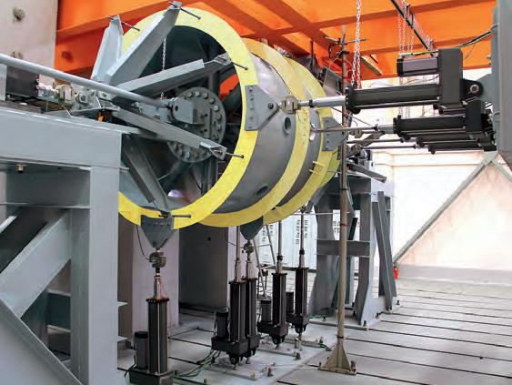
Now imagine that you need to remove data from one ADC, but for example, from hundreds or several thousand, and even with a frequency in the range of 5-200 kHz. You can also add real-time job requirements, lossless data logging, or considering them. In general, what is there to dream. It is easier to imagine a large enough stand for testing a car, engine or an airplane body.
If you try to organize data collection via a channel on a separate controller, then the cost of such a system will be comparable to the cost of the engine itself, or slightly less. This is where the Information Collecting Unit (BSI) comes to the rescue.
')
The BSI has different requirements for operating temperature, pressure, humidity, protection, etc. Many of these requirements for technology are regulated in the KT-160D standard. Depending on the conditions of use, this system can be assigned to a conditional class:
- Bench (industrial) application - working conditions: 0 ... +50 º C, humidity not more than 85%, no requirements for work in an atmosphere with reduced pressure, mechanical shocks and sinusoidal vibration.
- Field application - working conditions: -40 ... +70 º C, humidity not more than 95% within two hours, work in an atmosphere with reduced pressure up to 26.8 kPa, resistance to mechanical shocks of a single and repeated action up to 20 g, stability to linear acceleration.
- Application in harsh environments - Operating conditions: -55 ... +75 º C, humidity not more than 95% within two hours, work in an atmosphere with reduced pressure up to 0.26 kPa, resistance to mechanical shocks of a single and multiple action up to 150 g , resistance to linear acceleration.
This classification is very conditional, because before the development of the BSI is determined by the class of devices. The class is assigned depending on many parameters. For example, a civilian or military aircraft / helicopter imposes different requirements on vibration (I hope readers can guess why). Therefore, first choose the object of application, then the place of operation of the device in this object (non / habitable block pressure depends on it), the device class is assigned and only after the assigned class can the device be developed based on the requirements of standards and GOST.
Another way to develop a device is to first make and then refine to a certain class.
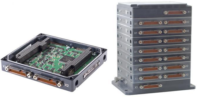
For tough conditions, the BSI are performed in a single package with group connectors. A single body allows you to make the structure quite rigid. By increasing the size of the block gets heated, protection from vibrations and shocks. Group connectors provide better tightness, now salt fog is not terrible. If tightness is not so important, then the dimensions will allow for normal ventilation inside the case.
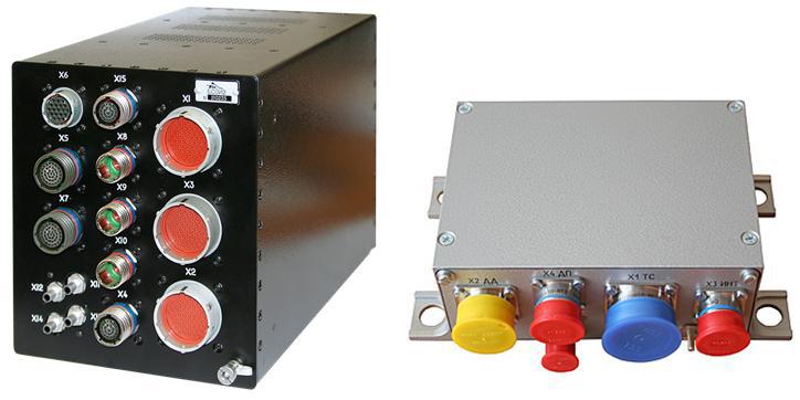
And this BSI is intended for field use. The requirements are softer, respectively, you can install individual modules:
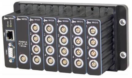
The main functions of the BSI are - data collection and storage. In addition to collecting the BSI, it can transmit data to an operator station, where the operator monitors the values of all channels in real time. Especially “smart” BSIs before receiving data allow you to program your channels (set the polling frequency, switching modes, input value ranges, connecting shunts and much, much more), save data from the channels, like inside (on NAND / Flash), and transfer to PC for later storage and processing.
Looking at the image of the BSI with individual connectors, you can partially understand what parts the BSI consists of.
Typically, the BSI emit the following components:
- The controller is a board with a processor that provides various interfaces for PC communication and data collection.
- Backplane (backplane) - in fact, a simplified motherboard, into which are inserted separate modules
- Power supply - here and so everything is clear. I would like to note that for harsh operating conditions at temperatures from -40 ° C, the power supply and the controller first start to warm up so that they can start after heating (to -30 ° C).
- Housing - is determined on the basis of requirements for external influences.
- Modules are separate boards that provide data reception from the ADC and their transfer to the controller.
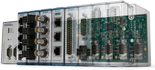
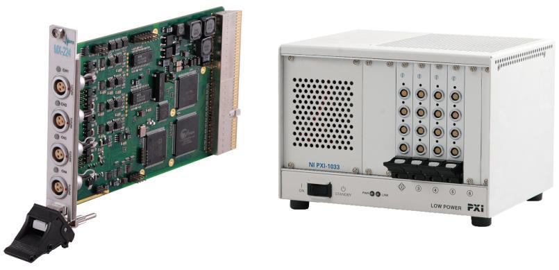
National Instruments clearly shows which BSIs they develop:
Consider a little more controller. At a minimum, it implements the following functions:
- device communication with PC
- module configuration
- receiving data from modules
- data processing (filtering optional)
- data transfer to PC
- data storage on NAND / Flash (optional)
As a controller core, you can consider several options (often found in practice):
- adsp 2191 - software for assembler, interfaces for PC communication (ethernet) - additional physics
- Cyclone III / IV - VHDL / Verilog software, Nios II soft processor (C / C ++ software), interfaces for PC communication (ethernet) - additional physics (IP cores for connection)
- OmapL137 / 138 - C / C ++ software, ARM9 / DSP core, built-in Ethernet
- Xilinx Zynq - ARM9 / FPGA, Built-in USB
To select the kernel, you need to figure out what the task is and how best to solve it. We return to our ADC.
In a multichannel system, a certain group of channels may be similar in characteristics. For example, channels for temperature sensors. If there are no serious requirements for the error and the sampling frequency of less than 1000 Hz, then there is no need for a separate channel to give a separate ADC. In this case, modules with a switched ADC are ideal.
On the switched module is located one ADC, several switches and a group input connector. Usually such modules have 4, 8, 16, 32 channels. Such savings on the ADC leads to some limitations.
With a polling frequency of 100 Hz for one channel, the polling period is 10 ms. During this time, you need to get one value from the ADC. A module with 32 channels must receive data from the ADC 32 times in the same 10 ms. For one channel, the time is reduced from 10,000 µs to 312 µs.
Data acquisition occurs as follows:
- switch channel
- subtract data from ADC
- transfer data to the controller (optional)
- switch the next channel
- etc.
Each of the operations takes time. For example, the recording of the SPI register config may take about 10-20 ms. Read ADC 1-5 µs.
But with such an algorithm for proofreading, side effects appear in the form of channel interference, when the value of physical. values on one channel starts to affect the other. To avoid this, between receiving data from different input lines, the ADC is switched to ground. During this time of grounding part of the charge from the previous channel goes away.
Thus, the notion of a cyclogram appears - switching channels and the ground to the ADC by hard timing.
For example, at a frequency of 100 Hz, switching of an ADC per channel is usually provided - 150 µs, to earth 100 µs.
If you set the values of the order of 5 μs, then you can observe a noticeable interaction, feeding different sinusoids to both channels. The less time the ADC spends between collecting data from different channels, the greater the interference, i.e. increases the error of the module.
The complete opposite of switching modules is modules with independent ADCs. Such modules can independently adjust a single channel - in frequency, in the range of input values and many parameters. It would seem that everything is great, only the cost of such modules increases due to a large number of ADCs.
The following article will address some issues from the following list:
- algorithms for obtaining data from the ADC
- choice of computational core for the controller
- choice of computational core for the module
- data exchange between modules and controller
- data acquisition from high-speed modules
Source: https://habr.com/ru/post/224389/
All Articles