Bootloader with AES-128 and EAX on AVR Assembler in 1024 bytes

Or how I stopped being afraid and fell in love with the assembler
One summer, I got a microcontroller programmer at my university. In the process of communicating with our chief engineer (hello, Alexey!), I learned that chips are cutting, projects are being stolen, customers throw and the appearance of a Chinese clone of our programmers for automotive electronics is only a matter of time, they can only be crushed by high quality. With all this, it is impossible to fall into paranoia, users are unlikely to want to work with our glands in collars with explosives.
A good security measure is software updates. Chinese clones automatically die after each new firmware, and loyal users get our love, care and new features. Robin Hoods in this situation, of course, will get their logical analyzers, HEX editors, and begin to pick the firmware process in order to satisfy the Russian-Chinese community.
')
Although we did not have projects that require such protection measures, it was clear: this should be done, sometime it will come in handy. Googled - not found, invented - done. In this article, I will tell you how to fit full 1-Kbyte encryption and why assembler is great. A lot of text, code and a little surprise for lovers of old iron.
Platform and language
We did all the projects on ATmega simply because in the CIS they are easier and cheaper to buy. As I understood from conversations with seniors, this is a very buggy family and you need to perform a lot of strange actions in order for it to work smoothly. We wrote in assembly language because tasks are extremely sensitive to the speed of work. It was impossible to rely on the compiler, and many parts of the code were calculated in cycles. Moreover, only the assembler can do the impossible.
Frankly, at first I was afraid to learn assembler, thinking that it causes irreversible brain damage and programmer disability. And it’s not just that people invented the C - assembler, it must be a very complicated thing. As it turned out, assembler is the easiest language in the world. There is nothing simpler than assembler. Blinking LEDs, enter interrupts and use the stack, I learned in one day and got to work. After a couple of months, there was enough experience to write the project, which will be discussed in this article.
There are no complicated abstractions in the assembler, which provides this blunt-headed simplicity. Specifically, in the AVR version there are not even cycles. To organize a cycle, you need to take a register, put into it the number of iterations, reduce the register by one at the end of the body and, if there is not 0 yet, jump (by some of the goto brothers) to the beginning of the body. You get used to such strange structures very quickly and stop being afraid.
What is a bootloader
A bootloader is a program that starts immediately after the microcontroller revives. What the bootloader does is decide the programmer. As a rule, bootloaders are responsible for some very system functions, such as updating software, loading the OS, or setting up the environment for the following programs. Our bootloader will perform a single function - to update the firmware of the microcontroller.
In the AVR architecture, a bootloader can be invoked in two ways - by setting a reset vector on it or by setting the BOOTRST fusion, which will force the microcontroller to start working not from the 0 address, but from the start address of the bootloader, the size of which is specified, again, in the fusions.
What problems may arise at this stage? Fuses can be edited. A highly intelligent "user" can, for example, reprogram BOOTRST and work will begin with a reset vector, not our boot. He can change the size of the bootloader, the microcontroller will start to perform some kind of heresy from the middle of the boot, and this may compromise the system.
So, we have to redirect the reset vector itself to our bootloader, and in its body place unconditional jumps to the beginning, in those places that correspond to different sizes of the rubble area. No problem.
The bootloader will determine whether it will execute a user program, or switch to firmware mode, based on the presence or absence of a level on a specific output.
Cryptography
Before starting work, I completed Part 1 of the cryptography course from Dan Bon on the Coursera. Professor Dan always talked about the fact that in no case can you write cryptographic systems yourself, this should be done by professionals, and not first-year students in their holidays. Of course. In justification, I can say that this bootloader is not positioned as an invulnerable to all attacks. Its existence is not a major, but an additional measure of intellectual property protection. In short, a person must dig into the update file, use the oscilloscope to stumble, suffer a week, think "well, to hell with it, pay $ 2000 to the Chinese, they will cut it" and do just that. The cost of software hacking should exceed the cost of physical hacking, no more.
The microcontroller is an open system, all engineers know how to work with it. Microcontrollers can jump commands at overclocking, can “forget” about protection at a certain undervoltage, can have very stupid holes, such as the ability to write and execute code in Flash from RAM, when reading is impossible (for example, ST92F). If you can literally change a couple of bytes of firmware, it will be completely merged. In the firmware, as a rule, there are areas with the expected structure - for example, unused interrupt vectors, which makes it easier to change a couple of bytes using the poke method. So, a simple block cipher in CBC / CTR mode is indispensable.
If you can not allow the possibility of changing the firmware - you have to use the message authentication code. Examples of such codes are CCM, GCM, EAX. Honestly, I already remember poorly why I chose EAX. Most likely, its future implementation in assembler seemed to me the most simple.
Each firmware will have its own, randomly generated key, connected as a separate file. The same file encrypts updates. Protection lies in the fact that we simply will not release new firmware for compromised keys. It is necessary to know each user by sight, but security requires sacrifice. Also, during key generation, some constants will be calculated, so that the microcontroller does not have to do it on its own.
EAX
How much documentation does an engineer need to write encryption? Two pictures taken from scientific work .

Auxiliary Algorithms
We guarantee the multiplicity of the data to the size of the block at the stage of encrypting the firmware, which reduces the pad function to M ^ B (31) and the variable P (32) will never be used.
At the stage of key generation, we can calculate the constant L (40) and, as a result, B.
“Exclusive or with an arrow” (31) means that B will be at-xor-en only at the end of line M.
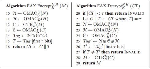
Encryption process
Where M is unencrypted text, CT is ciphertext, K is a key, N is the initialization vector, H is the header.
The assembler will need to write only the decryption function.
Let the message header H be set, unchanged and known only to us. This does not affect cryptographic strength, since it is assumed that the title is public information. Now you can calculate H '(23) at the stage of key generation.
If you look at lines 22, 24, together with 50 and 10, you can realize that the tsiferka in superscript with OMAC will go into the last character of the string with a length equal to the length of the block and will be used as the first block in CBC, ie, encrypted. Encryption of these lines can be carried out at the key generation stage. Moreover, only encrypted strings with the numbers 0 (L0) and 2 (L2) will be included in the key file to calculate N 'and C', respectively.
Having L0, B and N in hand, the calculation of N 'is reduced to E (L0 ^ B ^ N).
So, at the key generation stage, B, L0, L2, H 'will be calculated.
Together they will take 64 bytes.
AES-128
AES - brilliant in its simplicity algorithm. In addition, it has great flexibility, depending on whether we need capacity or volume. In our case, the volume and simplicity occupied is crucial. There are a lot of good articles written about AES, I will not go into details of its device.
The special feature of AES is that decryption is algorithmically more complicated than encryption itself. In the process of decoding, you need to multiply by 14 in the final field. Since we do not have wired multiplication tables in this horror, we will use AES outside the box - to encrypt the update on a powerful computer, we will “decrypt” it, and when decrypting it on a weak microcontroller - “encrypt”. There is no difference in cryptographic strength.
I have not come up with any effective (and safe) way to expand keys. Preparation of all 11 copies is performed at the key generation stage. In principle, for this reason, you can make the entire key block completely random - it will slightly increase the protection against brute force, if some pervert beaver chooses to do it.
The extended key will be 176 bytes. Together with the calculated constants, it forms a key file that takes forever 240 bytes of Flash. There are 784 left, that is, 392 assembler commands.
A vital and huge part of AES is the lookup table - the bytes to which the text bytes are replaced. The byte already has 256 possible combinations and the table will take as much flash memory. Unacceptable! So we will calculate it.
The substitution table is calculated as follows: first, the number that is the inverse of the element number of the table is found, then this inverse is subjected to the following affine transformation:
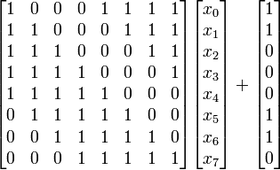
x0 ... x7 is the inverse number in the form of a vector. It needs to be written in an assembler and stored in less than 256 bytes so that there is a benefit. We are set to 88 bytes. Let's get started
Hello, world!
The assembler programmer always starts the program by simplifying his own life. It consists in renaming registers so that, for example, instead of r16 you can write temp_0. I, by tradition, call the 0 and 1 registers OP0 and OP1, 2 and 3 - NULL and OxFF (filling them with the appropriate values), and the rest - as necessary.
Registers
.def OP0 = r0 .def OP1 = r1 .def NULL = r2 .def OxFF = r3 .def b0 = r4 .def b1 = r5 .def b2 = r6 .def b3 = r7 .def b4 = r8 .def b5 = r9 .def b6 = r10 .def b7 = r11 .def b8 = r12 .def b9 = r13 .def bA = r14 .def bB = r15 .def bC = r16 .def bD = r17 .def bE = r18 .def bF = r19 .def temp_0 = r20 .def temp_1 = r21 .def temp_2 = r22 .def temp_3 = r23 .def temp_4 = r24 .def temp_5 = r25 In our case, we had to use almost all registers, from the 4th to the 19th, to store the decrypted data block. I took it to the registers because working with them is much easier and faster. Any activity with RAM in microcontrollers still leads to work with registers, why pay more.
Registers 20 to 25 are used for temporary storage of calculated data and are named accordingly.
From 26 to 32 are special 16-bit registers - X, Y, Z, used to address the memory. Moreover, only Z can be used to address Flash. As I heard, they physically have technical devices for increment, decrement and offset calculation, therefore, using them for other purposes, although it may be considered a bad practice, and can lead to unacceptable glitches in critical applications.
In addition to renaming registers, we calculate some useful constants - the number of bytes in a flash memory page, the size of the entire bootloader, the size of the cipher block, the number of memory pages, the number of data blocks per page, and the address to which the key file should be located:
Constants
.equ PAGE_BYTES = PAGESIZE*2 .equ BOOT_SIZE = 1024 .equ BLOCK_SIZE = 16 .equ PAGES = (FLASHEND+1)/PAGESIZE - BOOT_SIZE/PAGE_BYTES .equ BLOCKS_PER_PAGE = PAGE_BYTES / BLOCK_SIZE .equ KEY_ADDR = (FLASHEND + 1) — (BLOCK_SIZE*(11+4))/2 Add to the future miracle of flexibility - let us choose the connection speed by UART, port, output and the level at which we will decide whether to stay in the bootloader or continue the download. In addition to these utilitarian settings, you can set the address of the label to which the jump will be made, if the firmware is not required, and also decide whether the bootloader should remake the zero page of memory — the interrupt vector is located there and the attacker can overwrite the system.
Settings
;Reset address (Where to jump to if not asked to load boot) .equ RESET_VECT = 0 ;Is 0th flash page used? .equ USE_0th_PAGE = 1 ;////////////////////////PORT SETUP #define check_port \ port_settings \ /* use port letter... */\ /* A / B / C / D / E */\ C, \ /* check status of pin number...*/\ 5, \ /* load boot only if port is... */\ /* (S)ET (1) / (C)LEAR (0) */\ S ;////////////////////////BAUD RATE SETUP .equ Fosc = 16000000 ;clock frequency .equ baud = 19200 ;baud rate .equ UBRR = Fosc / ( BLOCK_SIZE * baud ) - 1 .if high( UBRR ) != 0 .error "Unsupported baud rate setting - high byte of UBRR is not 0!" .endif Now, let's deal with the RAM. AES requires 256 bytes for the replacement table. The data block consists of an initialization vector (16 bytes), the data itself (page size), an integrity check mark (16 bytes). To decrypt data, we need to generate a decryption sequence based on an initialization vector — another page size.
Staking a place in memory
.dseg .org 0x60 SBOX: .byte 256 ;rijndael substitution box ;these three SHOULD be consecutive SAVED_IV: .byte BLOCK_SIZE ;E(L0^N^B) RCVD_PAGE: .byte PAGE_BYTES ;page to be written TAG: .byte BLOCK_SIZE ;initially - precomputed header value ENC_IV: .byte PAGE_BYTES ;IV's to xor with page to decrypt .cseg On the ATmega16, with a page size of 64 bytes, the amount of RAM used is 544 bytes from 1024. On the ATmega8 it is 416. A bit too much. There are microcontrollers with large pages of flash-memory with a small amount of operational. Perhaps you can come up with something, but few people will need compatibility with the whole family.
With the preprocessor directives met, go to the assembler. The program traditionally begins with initializing the stack pointer, turning off interrupts, setting the NULL and OxFF registers, setting the UART settings.
Initialization
BOOT_START: ldi temp_0, low( RAMEND) out SPL, temp_0 ldi temp_0, high(RAMEND) out SPH, temp_0 cli clr NULL mov OxFF, NULL com OxFF ldi temp_0, low( UBRR ) out UBRRH, NULL out UBRRL, temp_0 ldi temp_0, ( 1 << RXEN ) | ( 1 << TXEN ) out UCSRB, temp_0 ldi temp_0, ( 1 << URSEL ) | ( 1 << UCSZ1 ) | ( 1 << UCSZ0 ) out UCSRC, temp_0 All this was enough for us as many as 6 different assembler commands, which are abbreviations or abbreviations. ldi - load into, mov - move, out - output to I \ O register, com - complement, cli - clear interrupt flag. As I said, the assembler is very simple. "Difficult" parts, with all kinds of incomprehensible UBRRH (UART Baud Rate Register High-byte), are described in detail in datasheets and are equipment settings.
We decide to stay in the buta or not. The selection of the port register, according to the user's settings, is performed at the assembly stage:
This is done by an elegant macro.
.macro port_settings /*PORT LETTER, PIN NUMBER, LOGIC LEVEL*/ cbi DDR@0 , @1 sbi PORT@0, @1 nop sbi@2 PINB, @1 .endmacro A little original will be the procedure for reading / writing to the serial port. Since we have little space and small speeds, I decided to combine confirmation of readiness for work with data acquisition and split the procedure into several, having different capabilities. In assembly language, it is very easy to do by calling a subroutine with different labels:
Readiness and receiving for 8 teams
;UART <- 0xC0 ;temp_0 <- UART confirm_and_read: ldi temp_0, 0xC0 ;UART <- temp_0 ;temp_0 <- UART UART_send: sbis UCSRA, UDRE ;skip next command if readiness bit is set rjmp UART_send out UDR, temp_0 ;temp_0 <- UART UART_read: sbis UCSRA, RXC rjmp UART_read in temp_0, UDR ret The sad part is complete, the world is built for future work. Let's start working.
88 byte lookup table
First, you need to find the number inverse to this in the final field. Such that when multiplying this number by this one, we get 1. The multiplication algorithm is described in the article on the wiki , I will not give it.
Finding the opposite in a finite field is a difficult task. Here we need to apply the advanced Euclidean algorithm ... but we are engineers. Remove computer science graduates from the screens. We are looking for the inverse element by brute force, using multiplication.
Search for an inverse element
ldi XH, high(SBOX) ;point X to SBOX memory location ldi XL, low( SBOX) ser bF ;first inc will overflow to 0 next_box: inc bF mov temp_1, bF ;save input in temp_1 cp temp_1, NULL ;if it's null - return breq sbox_byte_done ;return here mov OP0, OxFF ;so it overflows look_more: inc OP0 ;try next candidate ;temp_0 <- OP0 * temp_1 (in a Galois field) ;branching is fine, function used in precomputation only finite_multiplication: mov b0, OP0 ;operand 0 (candidate) mov b1, temp_1 ;operand 1 (current byte) ldi temp_2, 0x1B ;0x1B holder clr temp_0 ;multiplication result next_bit: lsr b0 ;operand 0 >> 1 brcc PC+2 ;if lsb of operand 0 was 1 eor temp_0, b1 ;xor operand 1 into result lsl b1 ;operand 1 << 1 brcc PC+2 ;if msb of operand 1 was 1 eor b1, temp_2 ;xor 0x1B into operand 1 cp b0, NULL ;while there are bits in operand0 brne next_bit ;work on it cpi temp_0, 1 ;if multiplication result was not 1 brne look_more ;inverse is in OP0 After that, we carry out affine transformation and save the result in memory. It is assembled from the simplest cubes. Programming in assembler is a great exercise for the brain. You can always find a more elegant solution, save a couple more teams, squeeze a couple more bars, and this saving on matches is sometimes a matter of life and death. This is a parallel magic world of programming, in which the coding process is turned into a constructor assembly.
Affine transformation in assembler
clr temp_1 ;affine transform result ldi temp_5, 0b11110001 ;matrix producer ldi temp_3, 0b00000001 ;current bit mask process_bit: mov temp_4, OP0 ;multiplicative inverse and temp_4, temp_5 ;and with matrix producer pop_next_bit: lsl temp_4 ;inv&matrix << 1 brcc PC+2 ;if it had msb eor temp_1, temp_3 ;sum bit into result cp temp_4, NULL ;while operand has bits brne pop_next_bit ;work on it lsl temp_3 ;move to next bit lsl temp_5 ;cyclically shift matrix producer brcc PC+2 ;if it had msb ori temp_5, 1 ;move msb to lsb cp temp_3, NULL ;while there are bits left brne process_bit ;process next bit sbox_byte_done: ldi temp_2, 0b01100011 ;0x63 eor temp_1, temp_2 ;xor it into result st X+, temp_1 ;save to memory cpse bF, OxFF ;if we're at last byte rjmp next_box ;we're done Mission Complete.
How fast does it all work? In the simulator - 2203268 tact. 0.27 seconds at a frequency of 8 MHz. I think this is a great speed.
We lost 256 bytes of RAM and 0.27 seconds at the start, saving 168 bytes of flash memory and solving a wonderful puzzle.
The substitution table is ready, the keys are expanded on the computer - there is everything you need to implement AES.
Assembled Encryption Standard
Let's start with elementary operations. At each stage of decryption, the key is summed with the data. The data is in the register file, from the 4th, there are 16 of them, and let the Z register always indicate the current key. Pointer registers can point not only to the SRAM or Flash area, but also to the register file, which greatly simplifies us life and speeds up the system.
Add round key
add_round_key: clr YH ;point to register file ldi YL, 4 xor_Z_to_Y: lpm temp_0, Z+ ;load key byte ld temp_1, Y ;load data byte eor temp_1, temp_0 ;xor them st Y+, temp_1 ;store back to data cpi YL, low( 4 + 16 ) ;check if it was the last byte brne xor_Z_to_Y ;if not - process next data byte ret Another simple operation is to shuffle the rows. Each row of data is cyclically shifted to the left by its sequence number. You just need to think about which byte with which one to swap and, finally, apply these useful skills of exchanging two variables in places without using an additional variable. Plus solutions - you can mix all these operations together for additional protection against attacks from third-party channels.
Shift rows
;cyclical shift: 0_row << 0; 1_row << 1; 2_row << 2; 3_row << 3 shift_rows: ;1st row eor b1, bD eor bD, b1 eor b1, bD eor b1, b5 eor b5, b1 eor b1, b5 eor b5, b9 eor b9, b5 eor b5, b9 ;2nd row eor b2, bA eor bA, b2 eor b2, bA eor b6, bE eor bE, b6 eor b6, bE ;3rd row eor b3, bF eor bF, b3 eor b3, bF eor b7, bF eor bF, b7 eor b7, bF eor bB, bF eor bF, bB eor bB, bF ;done ret Replacing all the data with the corresponding substitutions from the table would seem like a trivial task. A simple approach, on the forehead, has a fatal flaw: it is too linear. Linearity, immutability and clarity - potential vulnerabilities to attack by third-party channels. Roughly speaking, we have nothing to change in the implementation from time to time, without the immutability of the result, for an additional level of protection. We proceed otherwise. We will process one column at a time. We change the traversal order - and the attacker will suffer another week.
The substitution always follows the offset of the rows, therefore, we will not separate these procedures.
Sub bytes
substitute_shift_rows: ldi XH, high(SBOX) ldi XL, low( SBOX) movw OP0, X ;one column at a time clr YH ldi YL, 4 sub_next: movw X, OP0 ldd temp_0, Y+0x08 add XL, temp_0 adc XH, NULL ld temp_0, X std Y+0x08, temp_0 movw X, OP0 ldd temp_0, Y+0x0C add XL, temp_0 adc XH, NULL ld temp_0, X std Y+0x0C, temp_0 movw X, OP0 ldd temp_0, Y+0x04 add XL, temp_0 adc XH, NULL ld temp_0, X std Y+0x04, temp_0 movw X, OP0 ldd temp_0, Y+0x00 add XL, temp_0 adc XH, NULL ld temp_0, X st Y+, temp_0 sbrs YL, 3 ;XL == 8 rjmp sub_next Approaching the portal to hell. Before entering there, we need to invent multiplication by 2. From an engineering point of view, multiplying by 2 in the final field differs from the simple one in that after shifting to the left, add 0x1B to the result if the high bit of the multiplier was a single. If the bit was edinichkoy, then ... you can not use the transitions and conditions in the relevant parts of the cryptographic systems. No problem! Before the shift to the left, we will save the most significant bit and then we will write it in the right places of the empty register until we collect 0x1B there, if the bit was one, or 0 if it was zero.
Surprise. In my implementation, the multiplication procedure by 2 is located on one of the bootloader sizes. At the point of hit of this size, we place an unconditional transition to the beginning of the boot and, so that it does not interfere with living with each multiplication by 2, jump over it.
Sub bytes
;temp_0 <- temp_0 * 2 (in a finite field) ;temp_0 = (temp_0 << 1) ^ (0x1B & MSB(temp_0)) ;NO BRANCHING HERE ;uses NULL in a dirty way mul_by_2: bst temp_0, 7 ;store 7th bit in T bld NULL, 0 ;we form 0x1B in NULL if T is set rjmp cont_mul rjmp BOOT_START ;0x1F80. BOOTSZ can be here cont_mul: bld NULL, 4 lsl temp_0 bld NULL, 3 bld NULL, 1 eor temp_0, NULL clr NULL ret There is the last stage - the mixing of columns. The elements of each column undergo the following transformation:

Multiplication by 2 we wrote above. Addition in a finite field is exclusive or. To multiply by 3, you just need to add the number again to the result of multiplication by 2. The difficulty is that we, suddenly, write in assembly language, are limited in the amount of code and have a lot to count. Optimization will have to perform in the mind and comments. It is necessary to think very carefully about the course of calculations and use the registers wisely.
Mix columns
mix_columns: ;point to register file clr YH ldi YL, 4 next_column: ldd temp_2, Y+0x00 ;result0 ldd temp_3, Y+0x01 ;r1 ldd temp_4, Y+0x02 ;r2 ldd temp_5, Y+0x03 ;r3 mov temp_0, temp_3 ;r1 to operand rcall mul_by_2 ;r1 * 2 mov temp_1, temp_0 ;save r1 * 2 eor temp_0, temp_2 ;r0 + r1 * 2 eor temp_0, temp_5 ;r0 + r1 * 2 + r3 (lacks r2 * 3) std Y+0x01, temp_0 ;to r1 mov temp_0, temp_2 ;r0 to operand rcall mul_by_2 ;r0 * 2 mov OP0, temp_0 ;OP0 <- r0 * 2 eor temp_0, temp_1 ;r0 * 2 + r1 * 2 eor temp_0, temp_3 ;r0 * 2 + r1 * 3 eor temp_0, temp_4 ;r0 * 2 + r1 * 3 + r2 eor temp_0, temp_5 ;r0 * 2 + r1 * 3 + r2 + r3 (done) std Y+0x00, temp_0 ;to r0 mov temp_1, OP0 ;OP0 -> r0 * 2 mov temp_0, temp_5 ;r3 to operand rcall mul_by_2 ;r3 * 2 mov OP0, temp_0 ;OP0 <- r3 * 2 eor temp_0, temp_1 ;r3 * 2 + r0 * 2 eor temp_0, temp_2 ;r0 * 3 + r3 * 2 eor temp_0, temp_3 ;r0 * 3 + r1 + r3 * 2 eor temp_0, temp_4 ;r0 * 3 + r1 + r2 + r3 * 2 (done) std Y+0x03, temp_0 ;to r3 mov temp_1, OP0 ;OP0 -> r3 * 2 mov temp_0, temp_4 ;r2 to operand rcall mul_by_2 ;r2 * 2 mov OP0, temp_0 ;OP0 <- r2 * 2 eor temp_0, temp_1 ;r2 * 2 + r3 * 2 eor temp_0, temp_5 ;r2 * 2 + r3 * 3 eor temp_0, temp_2 ;r0 + r2 * 2 + r3 * 3 eor temp_0, temp_3 ;r0 + r1 + r2 * 2 + r3 * 3 (done) std Y+0x02, temp_0 ;to r2 mov temp_1, OP0 ;OP0 -> r2 * 2 ldd temp_0, Y+0x01 ;r0 + r1 * 2 + r3 eor temp_0, temp_1 ;r0 + r1 * 2 + r2 * 2 + r3 eor temp_0, temp_4 ;r0 + r1 * 2 + r2 * 3 + r3 (done) std Y+0x01, temp_0 ;to r1 adiw Y, 4 ;pointer to next column cpi YL, 20 ;if not done brne next_column ;process next ret Just a lot of arithmetic. In the calculation process, there are 6 memory accesses instead of the expected 4, but, as it seems to me, the maximum possible spatial optimization has been achieved.
So, all the necessary encryption steps for AES are written. Let's put them together. Keeping pointers to the stack before starting work and restoring them later is good practice. Almost always they are used somewhere else and the main program does not expect such a setup as changing pointers to memory in one of the procedures. The same applies to the status register. If you are not limited in space - always save the status register at the beginning of the procedure and restore it before returning!
Encryption itself
;performs a round of encryption ;using given expanded keys and s-box Rijndael_encrypt: push ZH push ZL push YH push YL push XH push XL ldi ZH, high(KEYS*2) ldi ZL, low( KEYS*2) rcall add_round_key ldi temp_0, 9 encryption_cycle: push temp_0 ;store cycle counter rcall substitute_shift_rows rcall mix_columns rcall add_round_key rjmp continue_enc rjmp BOOT_START ;0x1F00. BOOTSZ can be here continue_enc: pop temp_0 ;restore cycle counter dec temp_0 brne encryption_cycle rcall substitute_shift_rows rcall add_round_key pop XL pop XH pop YL pop YH pop ZL pop ZH ret Calculate how many bytes we packed. Addition with a key - 18 bytes. Multiplication by 2 - 22 bytes. Row shift - 50 bytes. The substitution is 62 bytes. Mixing columns - 94 bytes. Connect all this - 56 bytes. Total - 302 bytes. To understand that you did it is priceless. Slightly larger than the average size of the Windows executable header
The block cipher is good, but without a special encryption mode, it is practically useless. If the block cipher has nothing to do - it is also useless, therefore, let's get to the reception of data.
Information Exchange Protocol
The block of encrypted data in EAX, as in almost any other authenticated encryption scheme, consists of the initialization vector, the data itself and the signature. The initialization vector and the signature have the block length of the underlying cipher, the data itself is of arbitrary length, in our case the size of the Flash page. Remember the memory allocation step - the data block elements are arranged in SRAM sequentially, to facilitate the process of receiving data from the computer.
In order to simplify the design, we will not think about any fancy data format - we accept the firmware, which should fill the entire volume of Flash. All memory areas that are not directly involved in the firmware must be filled with random bytes. Thus, it is impossible to release a small patch that fixes just a couple of commands - the bootloader will change everything. It may be long, but safety is paramount.
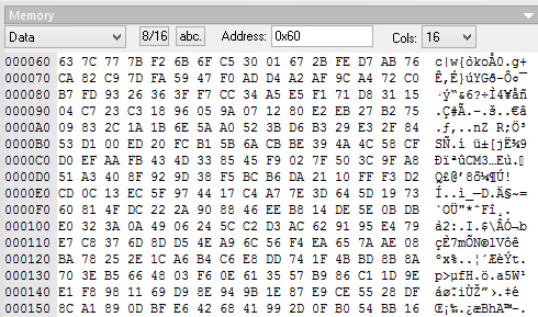
The data exchange protocol is the following: immediately after the replacement table is generated, the bootloader issues the byte 0xC0 (COnfirm) to the port and waits for the 0x60 byte (GO). After the readiness signal from the computer, the boot sets the Z pointer to the beginning of the recorded memory area, writes to temp_0 the number of pages to be received, decrypted and written, and proceeds to receive the page. It looks like this:
Beginning of work
wait_for_start: rcall confirm_and_read cpi temp_0, 0x60 brne wait_for_start ;/////////////////////////////PAGE ADDR INIT .if USE_0th_PAGE == 0 ldi ZH, high(PAGE_BYTES) ldi ZL, low( PAGE_BYTES) ldi temp_0, PAGES - 1 .else clr ZH clr ZL ldi temp_0, PAGES .endif next_page: ;save page counter and address push temp_0 push ZH push ZL ;/////////////////////////////BLOCK RECEPTION ;receive whole block ldi XH, high(SAVED_IV) ldi XL, low( SAVED_IV) ldi temp_1,( BLOCK_SIZE /*nonce*/ + PAGE_BYTES /*page*/ + BLOCK_SIZE /*expected tag*/ ) get_more_block: rcall confirm_and_read st X+, temp_0 dec temp_1 brne get_more_block As we remember from the listing of the confirm_and_read function, it first sends 0xC0, then waits for a response. This ensures synchronization with the computer in its simplest form - the software should send the next byte only with the full readiness of the receiving party. This, of course, is slow - it takes longer to receive and transmit data than to decrypt, which we will now deal with.
EAX Assembled
If we implement EAX exactly as shown in the Two Documenting Pictures - we will not fit into the volume. Therefore, we will correct the course of events.
The signature is the sum of the encrypted initialization vector (N, from Nonce), the data header (it is processed at the key generation stage) and the authentication code of the data itself, calculated using the CMAC \ OMAC algorithm. The signature calculated on the spot should be the same as the one sent to us. An exclusive or two identical numbers is 0. Therefore, we will summarize all calculated values directly into the resulting signature, and then check whether all of its values have been converted to 0.
We already know H '—the specified and processed header found in the key file. Immediately add it to the received signature:
Beginning of work
;/////////////////////////////TAG INITIALIZATION ;initialize precomputed header with tag ;tag <- H ^ tag header_to_tag: ldi ZH, high(PRECOMP_HEADER_TAG*2) ldi ZL, low( PRECOMP_HEADER_TAG*2) ldi YH, high(TAG) ldi YL, low( TAG) next_header_byte: lpm temp_0, Z+ ld temp_1, Y eor temp_0, temp_1 st Y+, temp_0 cpi YL, low( TAG + BLOCK_SIZE ) brne next_header_byte The next simple step is the calculation of N '. We have all the necessary data for this. We make life easier for us by highlighting all the manipulations with memory blocks in separate procedures. We may need to move the data block to the register file, add two data blocks by the pointer, etc. In two procedures, depending on the call mark, it was already located 9. I did not hear that such optimization was possible in a higher level language.
Secondary functions
;block <- block ^ Z xor_Z_to_block_RAM: ldi YH, 0 ldi YL, 4 ;Y <- Y ^ Z xor_Z_to_Y_RAM: ldi temp_2, BLOCK_SIZE ;Y <- Y ^ Z ( temp_2 times ) ram_xor_cycle: ld temp_3, Z+ ld temp_1, Y eor temp_1, temp_3 st Y+, temp_1 dec temp_2 brne ram_xor_cycle ret ;block -> SAVED_IV save_IV: ldi YH, high(SAVED_IV) ldi YL, low( SAVED_IV) ;block -> Y from_regs_to_Y: ldi XH, 0 ldi XL, 4 rjmp move_from_X_to_Y ;SAVED_IV -> block rest_IV: ldi XH, high(SAVED_IV) ldi XL, low( SAVED_IV) ;X -> block from_X_to_regs: ldi YH, 0 ldi YL, 4 ;X -> Y move_from_X_to_Y: ldi temp_0, 0x10 ;X -> Y ( temp_0 times ) ram_save_cycle: ld temp_1, X+ st Y+, temp_1 dec temp_0 brne ram_save_cycle ret Now, let's proceed to the calculation of N 'according to the Documenting Pictures. It uses the prepared at the stage of generating the key B and L0. Everything that happens, traditionally, is described in the comments. At the end of the calculation, the resulting N 'is summed with the signature.
Initialization Vector Processing
;/////////////////////////////NONCE ;block <- N ldi XH, high(SAVED_IV) ldi XL, low( SAVED_IV) rcall from_X_to_regs ;block <- N ^ B ldi ZH, high(PRECOMP_B*2) ldi ZL, low( PRECOMP_B*2) rcall add_round_key ;block <- N ^ B ^ L0 ldi ZH, high(PRECOMP_L0*2) ldi ZL, low( PRECOMP_L0*2) rcall add_round_key ;block <- E( N^B^L0 ) (nonce) rcall Rijndael_encrypt ;save calculated nonce rcall save_IV ;tag <- H ^ N ^ expected ldi YH, high(TAG) ldi YL, low( TAG) ldi ZH, high(SAVED_IV) ldi ZL, low( SAVED_IV) rcall xor_Z_to_Y_RAM For data encryption, EAX uses AES in CTR mode. This mode turns block AES into a stream cipher with which you can encrypt data of arbitrary length without any problems.The initialization vector is the just prepared N ', which, each block, is incremented by one and is encrypted.
Increasing by one is a problem; when we have a number of 16 random bytes, we will have to process all transfers to one, you never know. Nothing complicated.
Increment of 16 registers at the same time
;block++ ;all carrying is done properly increment_regs: ldi YH, 0 ldi YL, 20 clr temp_0 carry_next: ld temp_0, Y cpi temp_0, 1 ld temp_0, -Y adc temp_0, NULL st Y, temp_0 cpi YL, 5 brsh carry_next ret We add the encrypted initialization vector with the data - we get the decrypted data. We will not decrypt them before verification of the signature, they will be decrypted immediately before being written into memory. But N 'is ready, the memory for the decryption code is allocated - why not generate it?
CTR mode
;/////////////////////////////DECRYPTION IVs ldi YH, high(ENC_IV) ldi YL, low( ENC_IV) IV_calc_cycle: ;block <- E(IV) rcall Rijndael_encrypt ;ENC_IV <- E(IV) rcall from_regs_to_Y push YH push YL ;IV++ rcall rest_IV rcall increment_regs rcall save_IV pop YL pop YH cpi YL, low( ENC_IV + PAGE_BYTES ) brne IV_calc_cycle The hardest part is the message authentication code. It is based on CBC - not the most convenient for the implementation in the assembler encryption mode. Honestly, I don’t know why people still use CBC instead of CTR in everyday life. It requires alignment to block size, is not parallelized, has some funny vulnerabilities if it is implemented incorrectly and, in general, is more complicated. Fortunately, we took care of the alignment during the encryption phase of the firmware.
Note that B, according to Pictures, is summed only with the last block - at the end of the encrypted string. As in the case of the initialization vector, the obtained authentication code is immediately summed up with the signature.
CMAC / OMAC signature calculation
;/////////////////////////////CMAC / OMAC TAG CALCULATION ( block <- C ) ;X contains 20 after last save_IV command clear_registers: st -X, NULL cpi XL, 4 brne clear_registers ;block <- L2 ldi ZH, high(PRECOMP_L2*2) ldi ZL, low( PRECOMP_L2*2) rcall add_round_key ;last block is processed individually ldi temp_0, BLOCKS_PER_PAGE ldi ZH, high(RCVD_PAGE) ldi ZL, low( RCVD_PAGE) CBC_TAG: ;block <- block ^ m(i) ;temp_0 is fine rcall xor_Z_to_block_RAM push temp_0 cpi temp_0, 1 brne dont_add_B ldi ZH, high(PRECOMP_B*2) ldi ZL, low( PRECOMP_B*2) rcall add_round_key dont_add_B: ;Z is saved properly rcall Rijndael_encrypt pop temp_0 dec temp_0 brne CBC_TAG ;block <- H ^ N ^ C ^ expected ldi ZH, high(TAG) ldi ZL, low( TAG) rcall xor_Z_to_block_RAM We just installed the last part in the puzzle and we can check whether the signature came together or not. The condition of the signature validity - all its bytes must turn to 0. Traditional cryptographic verification - combine all values using OR into a separate register, no conditions. After the cycle is solved, write the data in Flash, or report a signature error and die.
Traditional secure signature verification
;/////////////////////////////TAG CHECK clr temp_0 check_more: ld temp_1, -Y or temp_0, temp_1 cpi YL, 4 brne check_more cp temp_0, NULL breq do_write rjmp die The die label sends us to an infinite loop, sending 0xFF to any request. The firmware should notice incorrect confirmation bytes and notify the user that the file is not suitable.
Eternal cycle of error
;/////////////////////////////TAG FAILURE AND EXIT die: ldi temp_0, 0xFF rcall UART_send rjmp die If the caption is correct - we restore the Z pointer to the current Flash page and proceed to the recording procedure. If this page was the last one, go to the upload_done tag, which sends the success byte to the firmware - 0x0C and goes into the death cycle.
All is well - go to the record
;/////////////////////////////TAG SUCCESS - CTR AND WRITE do_write: ;restore page pointers pop ZL pop ZH ;decrypt and write page rcall store_page ;restore page counter pop temp_0 dec temp_0 ;continue if not done, else - die breq upload_done rjmp next_page The procedure for decrypting and writing to Flash is unremarkable, I just followed the self-programming documentation. The only interesting place is an attempt to spoil the byte written into the Flash by the contents of the temp_0 register, which should contain the result of the signature packing. If the signature was correct - there is 0 in temp_0 and nothing will happen to the data. If for some reason the microcontroller successfully “flew over” all the checks and started writing in Flash - at least it will write garbage there.
The self-programming procedure is iron-dependent; when porting to other microcontrollers, it may be necessary to correct the call to the store program memory command.
Decrypt data and write to Flash
;D( RCVD_PAGE ) -> flash store_page: ;erase current page ldi temp_1, 0b00000011 rcall spm_it ldi YH, high(RCVD_PAGE) ldi YL, low( RCVD_PAGE) ldi XH, high(ENC_IV) ldi XL, low( ENC_IV) write_next: ld r0, Y+ ld temp_2, X+ eor r0, temp_2 ld r1, Y+ ld temp_2, X+ eor r1, temp_2 ;last countermeasure - if we jumped through tag check eor r0, temp_0 eor r1, temp_0 ;store word to page buffer ldi temp_1, 0b00000001 rcall spm_it adiw Z, 2 cpi YL, low( RCVD_PAGE + PAGE_BYTES ) brne write_next ;write page ;back to page start subi ZL, low( PAGE_BYTES) sbci ZH, high(PAGE_BYTES) ;write page ldi temp_1, 0b00000101 rcall spm_it ;to next page start subi ZL, low( -PAGE_BYTES) sbci ZH, high(-PAGE_BYTES) ;re-enable flash ldi temp_1, 0b00010001 rcall spm_it ret spm_it: in temp_2, SPMCSR sbrc temp_2, SPMEN rjmp spm_it out SPMCSR, temp_1 spm ret Putting it all together. Exactly 1024 bytes. It remains to flash the microcontroller, set up the fuses and write the client software.

Testing
We will not suffer from client software, we will write the key generator and the cryptographer of firmwares on Qt, with use of Crypto ++. Static header for encryption is inscribed there, tightly. All unused memory areas are filled with random bytes.
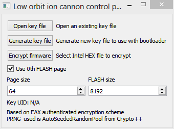
The flasher is elementary - wait for 0xC0, send 0x60 and, until the file is finished, send a byte in response to each 0xC0. Received 0x0C - everything is ready, received 0xFF - an error occurred. Let's write it on pure C for Linux. I don't have a COM port on my laptop, so ... we use the Psion 5MX, which is only 5 years younger than me.

We will get some board with ATmega8A from the bins of the homeland, we will boot it with a boot, connect the board with the MAX233 with a piece of board, assemble the flash driver on the Pioneer, rewind it all with random wiring, specify the port and the firmware file to the flash driver ... Restart the power supply ... The process has started.
Remember, no Arduino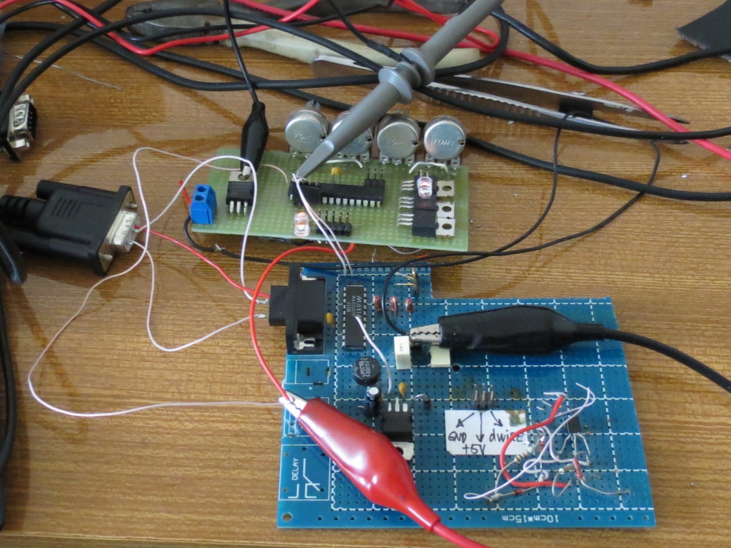
Something is clearly happening.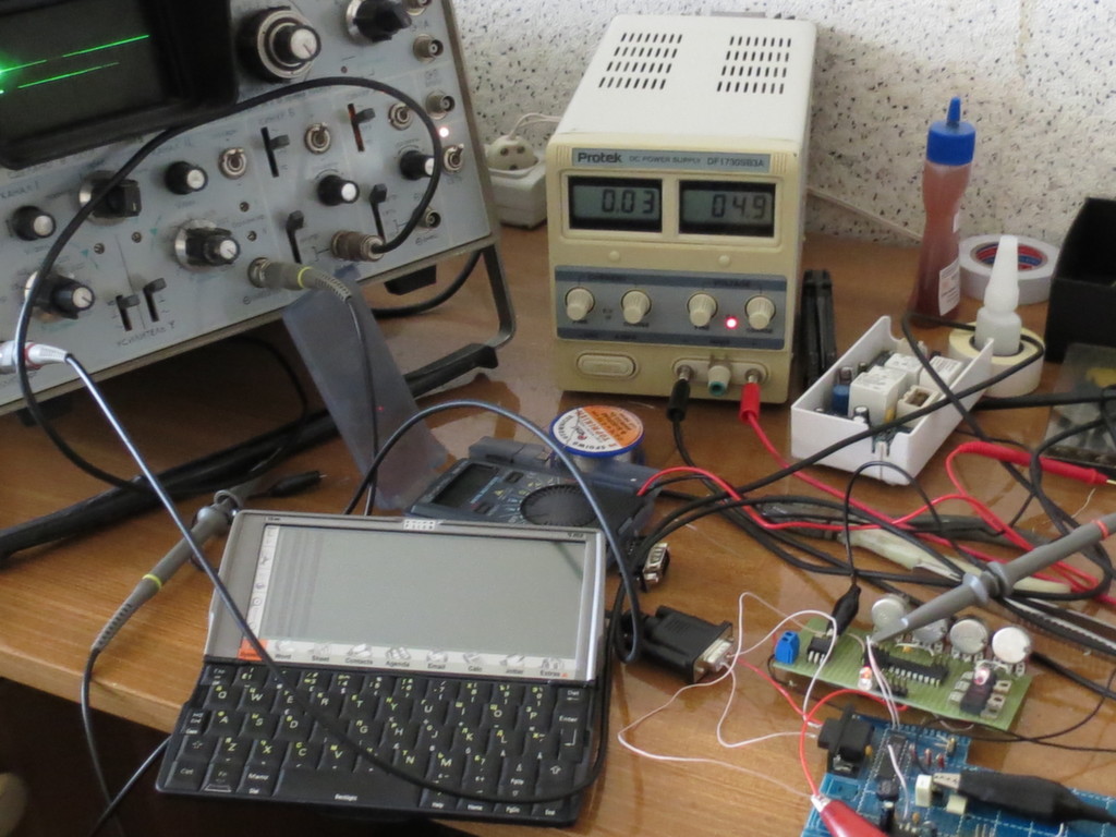
I apologize for the condition of the table and the test stand - the radio electronics engineer from me is not very.
The whole task of the test program is to turn off the LED and hang forever. After the firmware, it succeeds. Success!
Diligent Psion delivered 10KB to the port and is waiting for instructions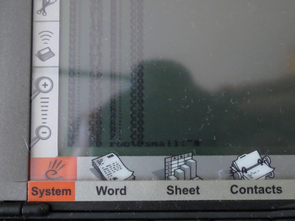
LED goes out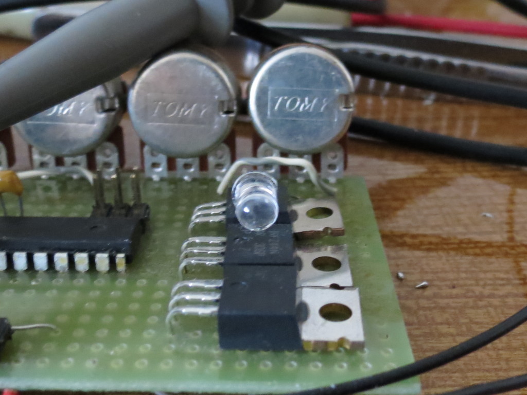
In this simple way, you can do the impossible and leave plenty of room for user code. Now there is a way to roll out patches, without worrying about the source being stolen by some kind of Chinese spy.
I would be glad if someone finds critical security bugs in my implementation.
All source codes and this article are distributed under the CreativeCommons Attribution-NonCommercial-ShareAlike license.

The repository on GitHub: github.com/sirgal/AVR-EAX-AES-bootloader
(all the code for the PC is written in a hurry and, sometimes, a year ago, I will be glad if someone wants to fix this horror, I do not have time yet)
Source: https://habr.com/ru/post/224383/
All Articles